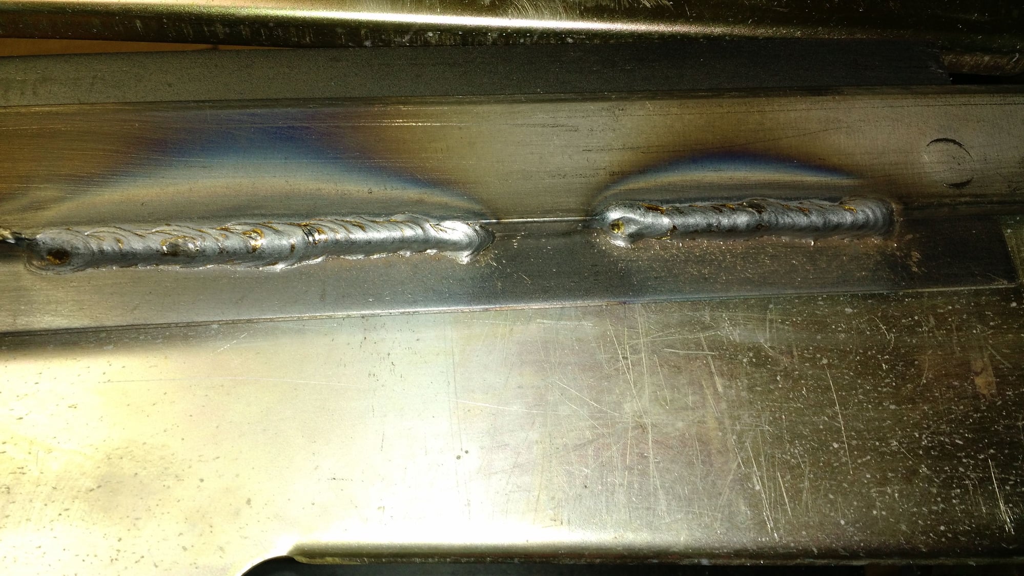
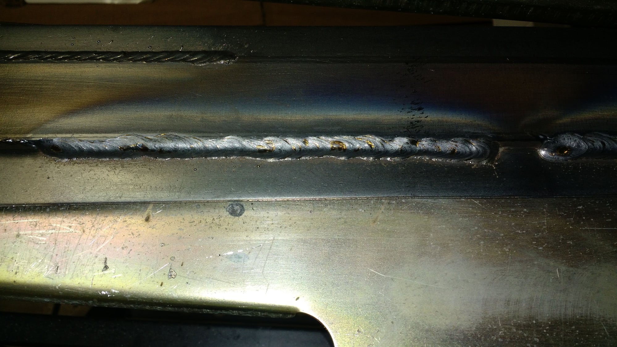
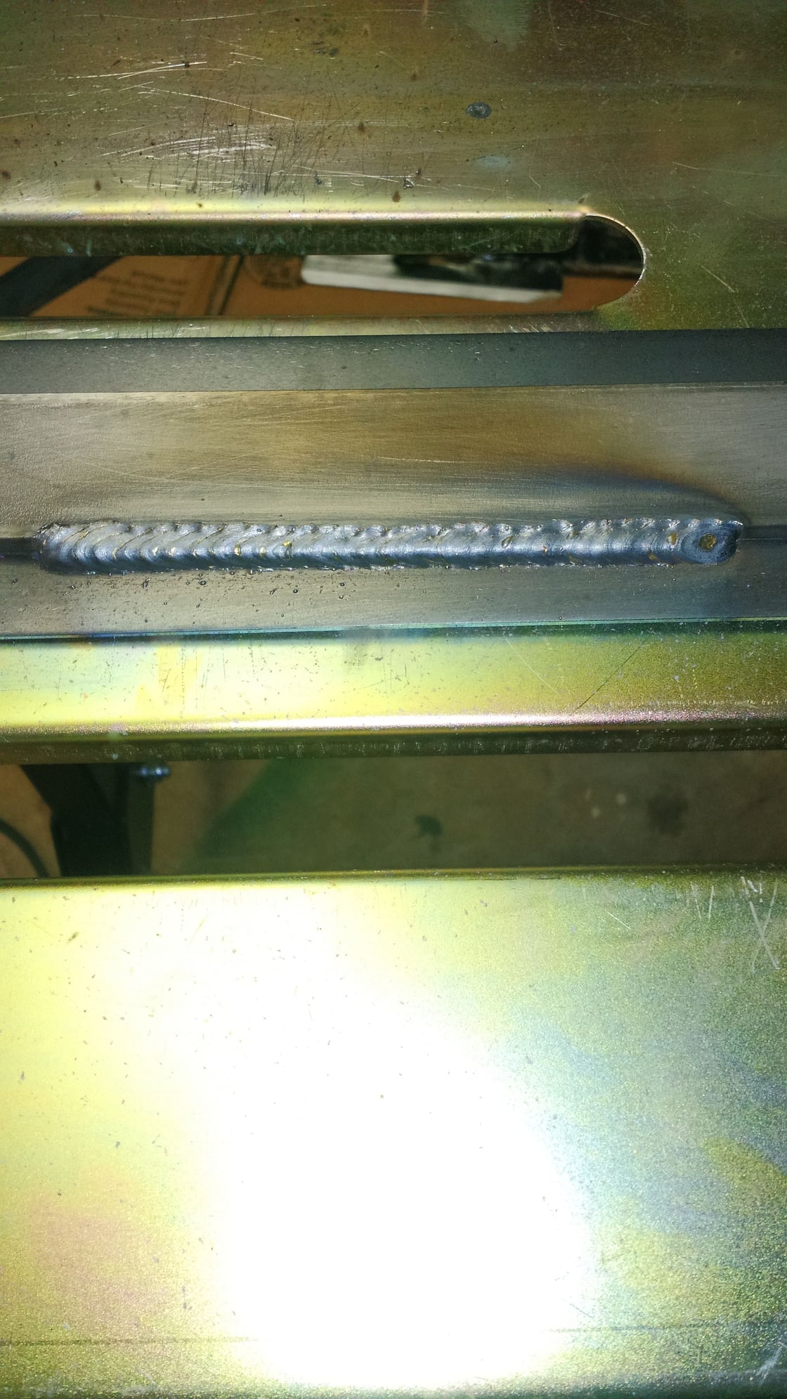
UMI subframe connector welding pics
#1
TECH Apprentice
Thread Starter
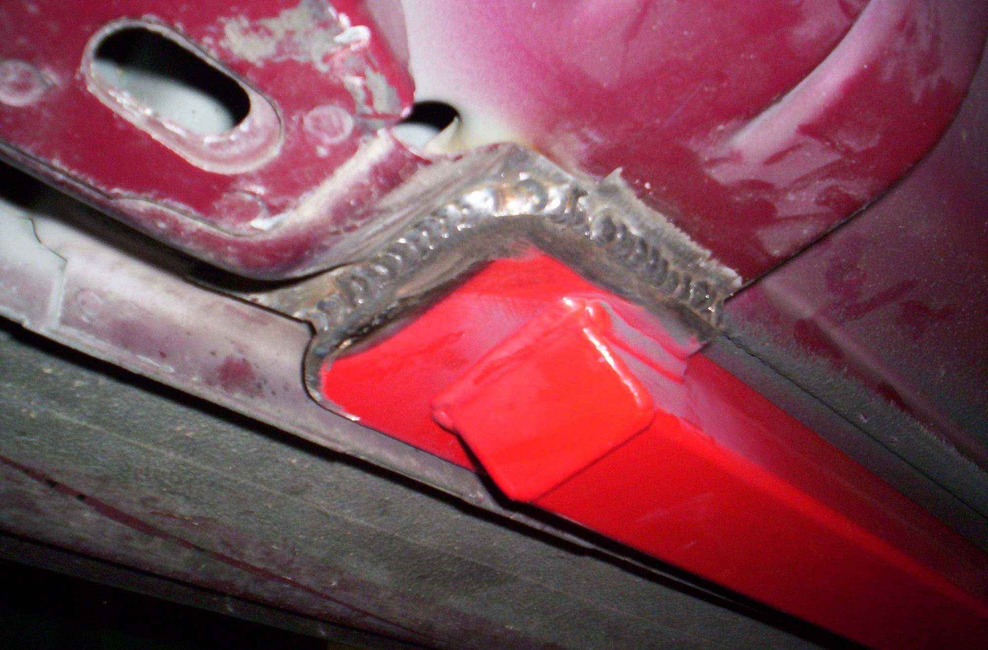
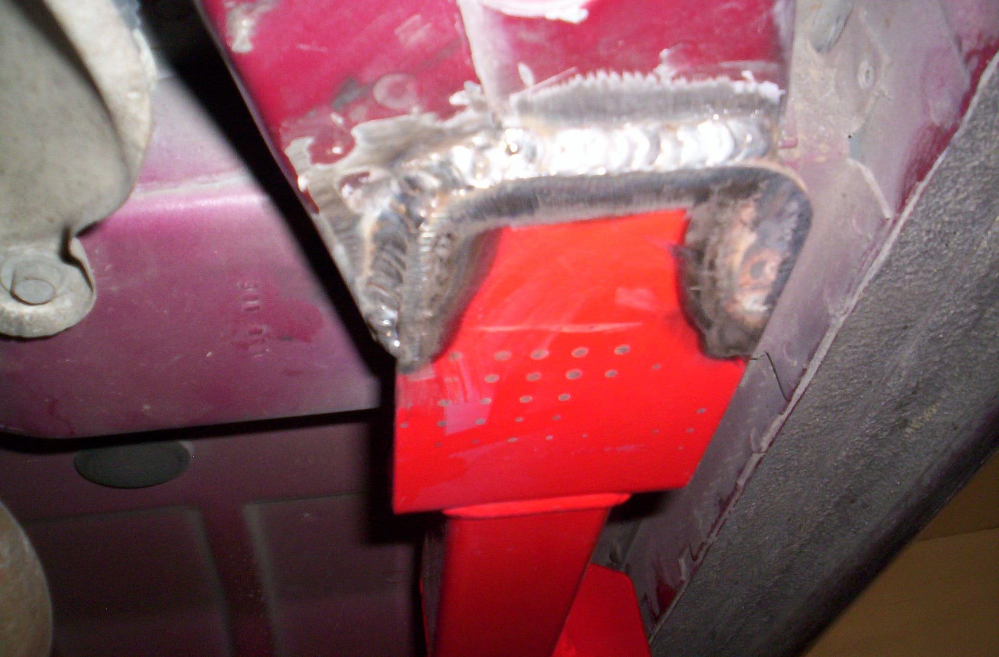
Please share some pics of how you or whoever welded your UMI subframe connectors in.
I've just about got the hang of welding fairly decent and want to practice the welds I am going to do before hand.
I've just about got the hang of welding fairly decent and want to practice the welds I am going to do before hand.
#5
TECH Senior Member
iTrader: (4)
I don't want to sound like I'm picking on Conan, I'm not. Since we are talking about techniques..... The first set looks to have been done with a series of "tack" welds. There's a crater in each one that tells me it was likely done with a mig welder as a series of single welds. Unless it was done for heat control reasons, the installer would likely be much better off laying down a single mig weld per side (or a series of "stitch welds about 1/2" to an inch or so long) than doing the single "spot" welds. MIG tends to start "cold" and it builds up heat as you weld (you can counter this by running the machine "hot" if it's a big enough machine). Starting over and over again isn't the best way to get good penetration (though heat builds up in the metal from the repeated welds and the pause between welds can be used to keep from burning through the thinner floor material). I'm not saying that those will fall off, they are likely on to stay. It's often done for appearance reasons and (if that is the case) it frustrates me when strength is traded for looks.
To answer the question on the second one, you shouldn't need to weld around the entire pad (other than it helps keep water out of there, you might make sure you goop any openings with a good coating of paint or something to seal it up). Those welds should be plenty strong (assuming good penetration). Most mig wire is 70,000 PSI tensile strength. It doesn't take a full perimeter weld to make things strong. There are strength benefits to minimizing the total amount of heat you put into the frame. So the stitch welds like you show are a good way to do a strong job that doesn't add a lot of additional heat to the joint.
My welding instructor constantly pushed me to "turn down the heat" and watch my heat input into my welded joints. I was always running things on the hot end and it took me quite a while to back the heat down and weld the joint with what was "needed" instead of what I wanted to do. He was always concerned with the total heat input to the joint and the "Heat Affected Zone" (HAZ) around the weld (the transition between metal that was heated while welding and metal that stayed relatively "cool"....typically this is where a proper weld will fail, not the joint, but the HAZ surrounding it).
If you're machine is set up with voltage and wire feed displays, try about 17.9-18.2 volts and approximately 200 inches per minute of wire feed speed with .035 wire and "drag" the weld instead of pushing (every machine is different, but try those and fine tune from there). That should get you about what you need to weld overhead.
Sorry that was so long.
I'm not a pro, but I'm a decent amateur. Your results may vary and people are always free to tell me I'm wrong.

Last edited by trackbird; 08-19-2016 at 10:16 AM.
The following users liked this post:
ebeTA_346 (04-25-2023)
#6
TECH Apprentice
Thread Starter
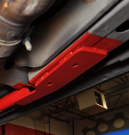
So the front mounting point for the UMI subframe connectors are 1/4 inch thick. The metal that they are welding to is only 1/8 inch thick... Well 2x 1/8 thick pieces in certain places.
What is the point in that? Not only do I have to overhead weld it. I also have to weld a 2x as think piece to the front subframe
What is the point in that? Not only do I have to overhead weld it. I also have to weld a 2x as think piece to the front subframe

#7
Moderator
iTrader: (4)
Join Date: Jul 2014
Location: My own internal universe
Posts: 10,446
Received 1,838 Likes
on
1,146 Posts
:word: welding upside down sucks
Trending Topics
#8
TECH Senior Member
iTrader: (4)
So the front mounting point for the UMI subframe connectors are 1/4 inch thick. The metal that they are welding to is only 1/8 inch thick... Well 2x 1/8 thick pieces in certain places.
What is the point in that? Not only do I have to overhead weld it. I also have to weld a 2x as think piece to the front subframe
What is the point in that? Not only do I have to overhead weld it. I also have to weld a 2x as think piece to the front subframe

Just point your mig gun/wire about 65-70% at the thicker plate and "wash" your weld to the chassis. You want to weld the joint between the materials, so you are going to weld the point where they touch (not "up on the thicker plate", weld the actual joint), just adjust the angle of your gun to put more of the heat and wire onto the thicker plate. Make sure you see the metal of the subframe melting/fusing with the bead. But you want to concentrate your heat on the thicker plate so you don't burn through the chassis and so you get enough heat in the thicker plate to actually fuse it together.
#10
TECH Senior Member
iTrader: (4)
I'd like to see the back side of them. That will tell me as much as the front. Those are looking decent. The bottom one looks pretty decent overall, but I think I'd like to see a bit more heat in the thinner plate. Also, I see what appears to be some "undercut" on the thick plate. They are the little "divots" where the edge of the bead melts the base (original) metal and pulls it away from the plate that you're welding. You'll want a touch more bead/wire in that area to fill that. Watch for the corner to melt off the thicker material and then you should see the weld bead "replace it" (or weld right up to the edge as it melts). I don't have a good example, but I'll attach a couple pics that might help a little.
One is a tig weld on 1/8" stainless (two 1/8" plates together) and the other is a stick weld on roughly 1/8" plates. I should have brushed the stick weld better, but what I want you to see is the "edge" at the top of both welds. See how there's a fairly straight line at the top? There's no undercut, it would show up as "low spots". The TIG weld is actually even with or slightly taller than the edge in most spots. The TIG welded plate is sitting on the edge of a welding table, that's the other plate of steel under it that isn't welded. It looks like it wasn't finished. lol. These aren't perfect, they have some bobbles in them (I had hand and elbow surgery not too long ago and I was having some issues getting things to go smoothly).
The stick weld was run without weaving from side to side, just straight down the middle until the weld filled out to the size needed and as I saw the edge of the upper plate "break" (melt and the edge starts to flow into the puddle), I'd move. I just kept a speed that allowed me to watch the edge form into the puddle and the bead to stay the same size/size I wanted.
Do those help any?
#13
TECH Enthusiast


