When you click on links to various merchants on this site and make a purchase, this can result in this site earning a commission. Affiliate programs and affiliations include, but are not limited to, the eBay Partner Network.
Have a valve job done, open the venturi up to ~90% of the valve diameter, and then blend it all in. I used to use snap gauges to measure the venturi.
Originally Posted by KCS
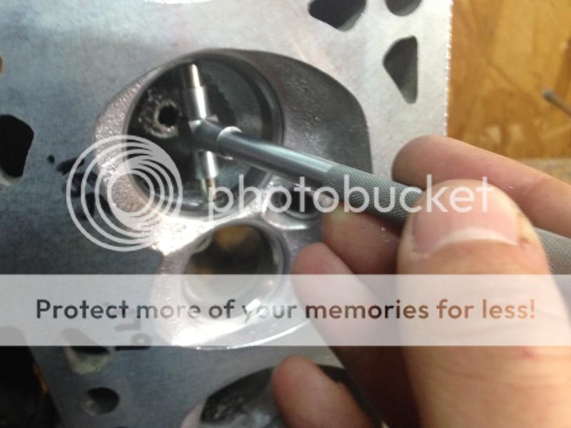
It was actually below the bottom cut. The thin line is the seat cut, it's about .040" wide.
Gotcha. Thanks. That's what ill shoot for. Same procedure for the exhaust? What's your thoughts on valve guide boss/rocker bolt hump? Fatten the exhaust runner any?
Gotcha. Thanks. That's what ill shoot for. Same procedure for the exhaust? What's your thoughts on valve guide boss/rocker bolt hump? Fatten the exhaust runner any?
I honestly really haven't messed with that much. I don't know how much narrowing the guide really helps besides increasing the cross sectional area. Just getting a good valve job, opening the venturi, and blending it all in is the best return on time and money invested IMO.
I'm in the same process with some reman 862s. I snapped my carbide so I just got s bunch in today.
My my understanding is that blending the bowl to the valve is beneficial. I'm also removing the swirl ramp and cleaning up around the valve guides but not reshaping them too much. I'm not touching the rocker bolt boss bc I don't I want to create a non smooth hole that's filled with a non smooth bottom bolt and I don't want to have to use thread sealer.
Swirl ramp is a efficiency and mpg thing that helps with idle and very low rpm fuel mixing/ air cavitation. But I've read that leaving it alone in stock form causes major cavitation at higher rpms. The airflow cavitation and reduced intake size causes rpm restrictions as well. Again this is what I've read and led me to removing mine.
I will be starting on mine this evening, pending arrival of my snap guages (per KCS advice, thank you.)
It seems like we are heading in similar directions. Do you think it's possible to partially remove the swirl ramp and have the best of both worlds?
I will be starting on mine this evening, pending arrival of my snap guages (per KCS advice, thank you.)
It seems like we are heading in similar directions. Do you think it's possible to partially remove the swirl ramp and have the best of both worlds?
Whats your plans on the exhaust side?
sure you can. I believe some main stream porter and a sponsor here uses the swirl ramps. But he completely reshapes them and does a full porting. He does amazing work but for me personally I don't care about efficiency in the sense of MPG/idle emissions. I tune in open loop and I run rich with anything off idle. My idle I'm in the 14.7-15.2. I also run a supercharger so getting the max flow out of my heads isn't worth the time to port them all out. Most people just turn up the boost but I can't with my maxed out supercharger. So if I spend 5-10hrs that will be it to open them up. A cam will make a lot more power than ported heads will. This for me is just to reduce the amount of obsticals to help reduce power loss. LS heads flow a ton in stock form and I'm rocking the OE 5.3 tiny intake valve
I also believe I've read that GM removed the swirl ramp completely starting in the Ls3. So if they felt that they could make more power and still have the efficiency without it then I don't need it either. It blocks a good bit of real estate in the intake tract.
The exhaust is getting the same as the intake. Removing the ridge below the seat for a smooth transition, remove any casting flash and slim Down the valve guide boss. I'm probably not going to go as far as polishing the exhaust but I'm cleaning out the spark plug bump in the chamber and might do alittle smoothing in the chamber.
This is after 20 min with a carbide that snapped. still have more shaping to do and then hit it with a tootsie roll to smooth it out some.
This was just a tootsie roll as I was annoyed the carbide snapped lol. Decided it was a waste a time and needed more carbides.
[QUOTE=KCS;19384059]Have a valve job done, open the venturi up to ~90% of the valve diameter, and then blend it all in.
My heads are back,
I examined that 90% figure this evening. It seems like quite a lot of material would have to come out. I didn't measure how much. So with a 2.00 valve, i'd need a 1.800 ID venturi opening?
What is the 90% based on? Or is it something that "just works" on these heads?
Last edited by wph351; 09-09-2016 at 08:55 PM.
Reason: Grammer
I would just hog it out so its a smooth transition to the valve seat. I wouldn't worry about a certain percentage.
Ive only used a carbide bit mostly. The exhaust port was just the 1 80 grit tootsie. The tootsie rolls I have are 80 and 120 only I believe. It got it for like $30 from harbor freight when I picked up the electric doe grinder. But thanks. It will look much better after I get in their with my new bits. I will only use the tootsies to smooth it all out.
to be on the safe side I wouldn't be taking too much out of the port. Only bc it's very easy to ruin the flow of the ports.
I examined that 90% figure this evening. It seems like quite a lot of material would have to come out. I didn't measure how much. So with a 2.00 valve, i'd need a 1.800 ID venturi opening?
What is the 90% based on? Or is it something that "just works" on these heads?
Yes, but it's not an exact number. 90% is a general rule of thumb. If you grind more than that, you start eating away your bottom cut, which might help CFM, but will hurt power. Some of the common CNC ported heads are about that big, maybe 91-92% tops. You need the bottom cut to help air transition to the valve.
I would just hog it out so its a smooth transition to the valve seat. I wouldn't worry about a certain percentage.
Ive only used a carbide bit mostly. The exhaust port was just the 1 80 grit tootsie. The tootsie rolls I have are 80 and 120 only I believe. It got it for like $30 from harbor freight when I picked up the electric doe grinder. But thanks. It will look much better after I get in their with my new bits. I will only use the tootsies to smooth it all out.
to be on the safe side I wouldn't be taking too much out of the port. Only bc it's very easy to ruin the flow of the ports.
Are you doing any unshrouding in the cumbustion chamber? Im at my bench examining these. It seems to me that the exhaust side could use just a little bit of widen on the "outboard" side.
I see what you are getting at. I think I'm going to steer clear of the bottom most cut. Leaving just a thin, untouched amount, of the "darker grey" insert material. Any thoughts on unshrouding?
Are you doing any unshrouding in the cumbustion chamber? Im at my bench examining these. It seems to me that the exhaust side could use just a little bit of widen on the "outboard" side.
well I just spent about 40 min and got 3 cylinders done with the new bits. I haven't don't the chambers yet besides a few of the spark plug ramps and it was very quickly. Still need to tootsie roll it.
Minor sure about the unshrounding at the moment. Prob not only bc I have small chambers and small bore 5.3. I prob won't do much besides polish the chambers slightly and remove/smooth out the spark plug swirl ramp.
I did notice that the small 1.89 5.3 intake valve has very little restriction where the bowl meets the valve seat. I could see where this would be a restriction on the larger 5.7 and 6.0 intake valves. I have more of a restriction on the exhaust side.
Heres what I just did
Exhaust
Intake
Stock exhaust. U can see the machined ridge right below the seat. Half moon light band
Lol I'm just doing it. No slowing down. The electric die grinder and the correct bits make a huge difference in cutting speed.
What at bits and drill are you using?
Yup up your doing it right. That's the spot I felt the ridge on my exhaust side. Intake not so much. Remember you want the intake side to be rough and the exhaust side to be smooth. So I wouldn't go finer than 120 on the intake, exhaust you could def do the 240 if u got it.
I see what you are getting at. I think I'm going to steer clear of the bottom most cut. Leaving just a thin, untouched amount, of the "darker grey" insert material. Any thoughts on unshrouding?
Unshrouding is good lol. I usually put the head on a bare block and scribe the outline of the bore onto the cylinder head, then deshroud to that line around the valves, but without removing too much in order to keep the chamber volume low.
I know some cylinder head guys will open up the chamber even further, like 4.125" wide chamber going on a 3.905" bore. I don't know if there's really any benefit other than flowbench numbers though.
Lol I'm just doing it. No slowing down. The electric die grinder and the correct bits make a huge difference in cutting speed.
What at bits and drill are you using?
Yup up your doing it right. That's the spot I felt the ridge on my exhaust side. Intake not so much. Remember you want the intake side to be rough and the exhaust side to be smooth. So I wouldn't go finer than 120 on the intake, exhaust you could def do the 240 if u got it.
I'm using the harbor freight electric die grinder. It had WAY to much rpm and actually bent my long mandrel burr bit from revving so fast. I set up an outlet running off of a dimmer switch to control rpm. Works nice. I have an eastwood port kit with the 4 long mandrel bits. I also ordered 80,120,240 cylinders and tapers.
I'm using the harbor freight electric die grinder. It had WAY to much rpm and actually bent my long mandrel burr bit from revving so fast. I set up an outlet running off of a dimmer switch to control rpm. Works nice. I have an eastwood port kit with the 4 long mandrel bits. I also ordered 80,120,240 cylinders and tapers.
yup that's what I'm rocking as well, I just run the die grinder from a plug and deal with the RPMS. But for you to bend the long mandrel yours must be too thin. What's the DIA of the Mandrel shaft? I think the ones I got are 6mm or 8mm DIA. They are thick as hell, basically 1/4" to fit the 1/4" die grinder Idk how you bent one lol your not suppose to push down on the bit when it's cutting. Basically it will do all the work, u just move it where you want it. Last thing u want is to load it up or dig and get wedged and shatter the carbide.
i spent 4 hours today and finished up one head completely. The 4 hrs included the cleaning and reassembly of the head.
I removed the swirl ramps, and blended the bowl around the guide. Tappered the valve guide for flow and removed any of the valve seat ridges. Intake didn't need much due to the smaller valves. The exhaust actually had some of the 82* valve seat showing so I removed that. The exhaust I decided to fully sand the exhaust runner to smooth it out some, sanded down to a 120 grit and it's pretty smooth. Tapering the valve guide and opening the valve seat machining really opened it up. Hopefully the 120 grit is smooth enough, def smoother than the original casted finish by far.
Then I decided to look into the chambers. Decided to unshround the exhaust valve alittle and polished around the exhaust valve in the chamber. Then I decided to smooth out the rest of the chamber but more just polished around the exhaust valve. The chamber finishes are so rough that's why I decided to smooth it out alittle. Of course I smoothed out the spark plug bosses.
Cleaned them out and put it all back together. Swapped the OE springs for high lift/higher rate howards beehives. Fit together like stock. But good for .600 lift and has alittle more spring rate than PAC 1218s and only cost $120.
U shrouding the valve
Finished intake finish
Finished exhaust
Chambers
Dynamic duo!
All done! I used permatex engine assembly lube for the guides and locks so it's lubed for a long long time till engine startup. Stuff is awsome and I've used it on my last 3 motors.
Actually it bent touching nothing! Youd have to be a caveman to do it while shaping material. These are 1/4 mandrels. My 6" Christmas tree flopped over as soon as the rpms hit it. I Thought about calling eastwood and complaining. Instead I just cut off the mandrel above the bend and wired in the dimmer to adjust the rpm. No problems since.
It's tough to see your exhaust valve unshroud. Have any other pictures of it? Your work looks nice. The motor should be happy with those torqued down on top.
Wow, eastwood china crap. They are like a more expensive harbor freight. Literally I see their stuff (i Have some of it) and its all made in china and I can usually find it cheaper online.
I saw their bit kits and I see the same ones on ebay right from china. I recommend getting real USA made carbides... you will thank me later lol. I just picked up 10 used bits for $35 shipped from a guy on ebay that sells them from a company. They are USA bits and they have been amazing thus far even being slightly used. These bits new are $20-40 each!
Sorry i dont have any pics on me. I didnt do "alot" I had a machining mark on the side of the chamber for the intake and exhaust. I took the small carbide and smoothed out the cut (removed alittle) and then blended that to the rest of the camber on that side. It wasn't alot "removed" but I also dont want to drop compression. A stock 5.3 has low compression already. I would say maybe 1mm removed. The smoothing of the machine cut should free up some of the flow.
Thanks, I hope they are an improvement. Need these bad boys to spin to 6000-6500.
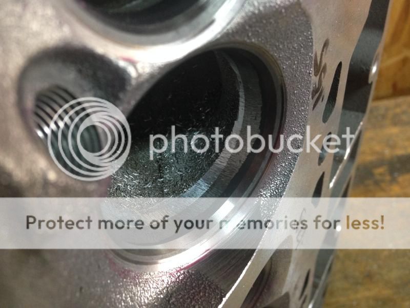
I've been going back and looking at your pictures. One thing on the exhaust side stands out to me. I've attached a picture of one of my stock exhaust ports looking from the cumbustion chamber.
The O.D. of the valve guide is pretty much flush with the port. Yours is much farther away. Did you remove a ton of material or is this just a casting difference between the 2 different heads?


 09-07-2016, 04:57 PM