When you click on links to various merchants on this site and make a purchase, this can result in this site earning a commission. Affiliate programs and affiliations include, but are not limited to, the eBay Partner Network.
Mouse, do your cans have a drain on them? Really like what I see, nice pieces. For a non boosted application, is the breather necessary or could a closed style can be used? Looking at your draft can, probably what I'm going with.
Edit- Website says maximum capacity is 8oz, verifying this is correct.
Last edited by FIVEPOINT7; 11-08-2016 at 05:45 AM.
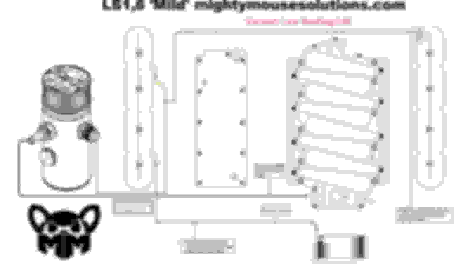
MM, can you explain the difference in routing between the two following diagrams? I ask because I've seen it routed both ways. In both cases, assume that there is a PCV valve used just after the intake and that the can has a breather on it. In the 2nd pic, the green line on the bottom isn't connected to the blue or orange lines, just passing over it. Right click on images and "open in a new tab" to see them enlarged.
Last edited by 5.7stroker; 11-08-2016 at 08:53 AM.
on you drawing pcv air can short cut the system going in and out of the same valve cover instead of having to go all the way across the engine, not my favorite.
merging two hoses to a single hose the same size as the first two does not add flow capacity to the system, so one this one for stock to bolt-on hp a merge is not necessary.
the 'pcv orifice' fits neatly into the ls1 driver valve cover and can increase crankcase vacuum during normal driving when used to the throttle body with the pcv can
there are 3 good reasons
however on some cars, installs, and owner preferences there are just compromises
this line configuration is only possible with the pcv can, otherwise engine damage can certainly result.
So, If I understand the above diagrams correctly, I could run a vacuum line from the rear of the driver side valve cover directly to the throttle body, which is going to be the 'fresh air' source. Then run another vacuum line from the front of the passenger side valve cover to the catch can, then through the PCV valve and into the intake, and block off the rear passenger side valve cover outlet, and it would work? No boost on my system at all.
So, If I understand the above diagrams correctly, I could run a vacuum line from the rear of the driver side valve cover directly to the throttle body, which is going to be the 'fresh air' source. Then run another vacuum line from the front of the passenger side valve cover to the catch can, then through the PCV valve and into the intake, and block off the rear passenger side valve cover outlet, and it would work? No boost on my system at all.
It looks like that's what the first of the two diagrams shows. The line from the rear fitting of the passenger side valve cover is optional
So, If I understand the above diagrams correctly, I could run a vacuum line from the rear of the driver side valve cover directly to the throttle body, which is going to be the 'fresh air' source. Then run another vacuum line from the front of the passenger side valve cover to the catch can, then through the PCV valve and into the intake, and block off the rear passenger side valve cover outlet, and it would work? No boost on my system at all.
There are many ways to do it. as long as your catch can does not introduce a vacuum leak to the intake manifold that is one way to do it.
الان يمكنك الحصول على نموذج خطة البحث العلمي من خلال التواصل مع اكبر فريق عمل داخل مكتبتك لتتعرف على افضل الخدمات كما يمكنك الان الحصول على نسختك كاملة ومتكاملة العناصر الخاصة بخطة البحث العلمى وفقا لمعايير الجامعات فى اسرع وقت من خلال شبكة المعلومات العربية اتصل بنا الان او زور موقعنا
الان يمكنك الحصول على نموذج خطة البحث العلمي من خلال التواصل مع اكبر فريق عمل داخل مكتبتك لتتعرف على افضل الخدمات كما يمكنك الان الحصول على نسختك كاملة ومتكاملة العناصر الخاصة بخطة البحث العلمى وفقا لمعايير الجامعات فى اسرع وقت من خلال شبكة المعلومات العربية اتصل بنا الان او زور موقعنا


 11-08-2016, 05:37 AM