When you click on links to various merchants on this site and make a purchase, this can result in this site earning a commission. Affiliate programs and affiliations include, but are not limited to, the eBay Partner Network.
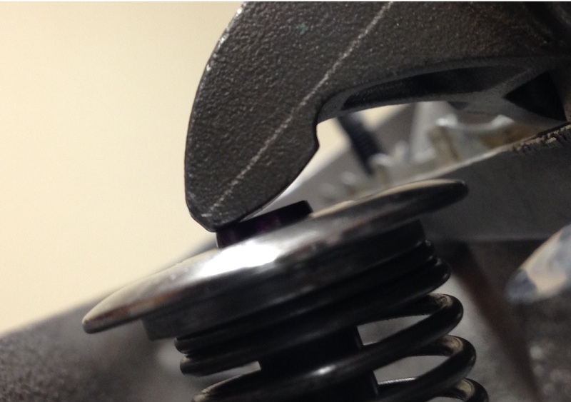
So this happened over the weekend . I thought the TFS heads where setup to run the stock rockers .
They have to be shim up 3mm to get proper rocker arm geometry .
So now I guess I need to find some 3mm thick aluminium washers . big hammer replied to another post that Mast uses them .
Something is wrong there. You shouldn't need that much shim and stock rockers usually don't have that narrow of a wipe pattern. What dos it look like from the side view?
Something is wrong there. You shouldn't need that much shim and stock rockers usually don't have that narrow of a wipe pattern. What dos it look like from the side view?
Those photos are of the solid lifter on the base circle and not the swipe .
I don't get that. What's your method for determining proper geometry?
Again this is at the base circle of the cam and nothing more. We were thinking that this was a little too far to the inside of the valve stem.
We install a solid lifter rotated the assembly and check for swipe. Swipe went a little past half of the valve. Unfortunately I did not take any pictures of the swipe pattern across the stem of the valve. Should I be doing it another way ?
Last edited by 1973 STEP A SIDE; 05-02-2017 at 10:35 AM.
Again this is at the base circle of the cam and nothing more. We were thinking that this was a little too far to the inside of the valve stem.
We install a solid lifter rotated the assembly and check for swipe. Swipe went a little past half of the valve. Unfortunately I did not take any pictures of the swipe pattern across the stem of the valve. Should I be doing it another way ?
I understand it's at the base circle, I don't understand why that would show good rocker geometry. Looking at those pictures you posted and considering that those marks were made with the lifter on the base circle of the cam, it looks like the geometry is waaaaay off.
With stock rockers, looking at swipe isn't really a good way to determine geometry. That's more for the roller tipped rockers. The tip of the stock rockers are like the legs of a rocking chair and with higher lift cams, you should be using the full arc of the rocker tip. By shimming up the rocker, you've narrowed it down to probably the last half of the arc. When the valve is fully open, the sharp radius at the end of the tip could dig into the valve tip.
This is my stock LS3 rocker with ~.645" valve lift.
If I were to raise the stand like you did, I would have more of the sharp radius at the rocker tip digging into the valve.
Okay I will get into it tonight and take some photos and post them. I do appreciate all the help that I can get thanks.
That doesnt look to bad to me. Is that without the shims? Its hard to get a good angle to see the contact area at max lift but it looks like your not up on the tip and using most of the valve tip.
I'll post these pics to show others what the effects of shimming are. Wish I still had the .080 shim pics because you could really see how the rocker got up on the tip and started scrubbing backwards. I ended up shimmimng mine .025" because i didnt like how the rocker was out on the edge of the valve tip while valve was on the seat.
KCS I owe a few beers !! This is what you get when you have a small block guy help you finish the gen4 long block )-:
I fell like I just got gut punch !! Now what do I do ?? Buy roller rockers ??
I agree, that looks a lot better that what expected based off those first valvetrain pics. I see now why you may have needed those shims though. Those are not stock length valves. The keeper groove to tip distance is probably .250" greater than a stock valve, which could be making things more complicated than they need to be. You can see how much more your valve sticks up above the retainer compared to my pic with the stock GM valve.
At this point, I would get in touch with TEA and get their input. If it was my engine, I would want to take those valves out and put in stock LS3 valves if that's even an option. That should simplify the geometry and take a considerable amount of weight out of the valvetrain.
You'll build better torque on LLSR and the valvetrain stability will help it carry power well past peak. I do not think you'll regret it at all!
I've been DD mine now for a year and a half. Until it warms up it acts like a bigger cam. Then it settles down and drives.
Mine is 237/245. Drives like a 232/240 warm. Makes power like a 237/245. Carries power out to 7400 at least. I haven't revved it higher. 500 + hp from 6300 out to the end of the run.
LLSR is going to help eliminate a lot of the valvetrain noise common to aggressive cam lobes, the dreaded sewing machine on steroids. Nice rockers! I bought the same ones for my build. The kit comes with a set of rocker arm geometery checking tools, it'll be interesting to see how that works out with parallel measurements.
WHAT I FOUND : The END plate bolt locations can "strip"
My METHOD is to "sert" the end bolt holes under the plates.
This location is in the head outside position (4).
The "swipe" picture should show the MAX LIFT position close to the valve stem center.
I see you have improved this location.
 04-25-2017, 11:26 AM