
csi water pump failed - low voltage?
 07-18-2017, 09:13 AM
#21

Seems you are confused. The female "plug" is the one coming from the pump even though the prongs are male. The one you cut off is the male "plug" pigtail supplied with all CSR pumps. The male plug on their website is what you need according to your pictures. https://www.csr-performance.com/shop...csr-waterpumps
Edit: I called CSR to doubly confirm and lt1-xjs is right. My bad!!! I ordered another pigtail, should have it by the weekend. Rather spent 7 bucks than 100 for a new mechanical pump.
Last edited by timaishu; 07-18-2017 at 10:58 AM.
 07-22-2017, 01:51 PM
#22
UPDATE:
I got my new pig tail from CSR as I though that was the problem. I put the new harness on and same thing, pump wont go on. Put my jerry rigged wiring back in and the pump wont turn on. What? it just worked last time..
Took my battery to autozone and had it recharged to rule that out - battery was low, but they recharged it.
Hard wired the battery direct to the pump and the pump turns on!
Okay this is the weirdest part.. When I have everything wired up and I stuck the postive tester in the back of my test wire at the pumps harness (last point in the electrical system before the pump) and the negative end to a different clean ground bolt(same result as using the pump ground, but I wanted to rule out a grounding issue, which I found it doesnt have). With it like this I get pretty much no voltage, but the moment I take the postive test terminal off the pump, I get 12v, put the terimnal back on pump, no voltage.
Wtf is going on? I am at my whits end, this doesnt make sense to me. Kind of at the point of ripping out all the wiring and putting it all in brand new, or going back to mechanical again.
How can I get 12v out the harness, but when the harness is on the pump, it reads no voltage?
Last edited by timaishu; 07-22-2017 at 01:59 PM.
07-22-2017, 03:08 PM
#23
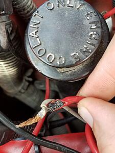
Well I think I figured it out this time. Traced the relay wiring. Found a taped bundle. Untaped them and its pretty ghetto. All are soldered, but all but 1 are just twisted, solder dabbed in then taped. One was soldered with a twice connector on top. One that was solder was burned to a crisp with only a few strands hold it together. The burned one is probably going bad under load..
I am going to cut these off and redo them all.
I am going to cut these off and redo them all.
 07-22-2017, 04:29 PM
#25

might want to just replace all that ghetto wiring with new wire right from power/relay source so there are no "splices"...
any EWP is only as good as the wiring/relay/fuse install
any EWP is only as good as the wiring/relay/fuse install
07-23-2017, 12:45 PM
#26
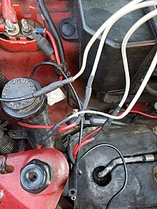
Just replaced all the ghetto solder splices with (i think better) cranked down butt connectors that are heat shrinkable with adhesive on the inside to keep it from sliding out, then another layer of heat shrink on top. I also redid the ground wire. Only thing I wish I did that I didnt think about until after is sliding heat shrink into the harness to seal up the connector so it doesnt corrode. But I will think of someway to seal that up later (maybe some sort of glue?)
I just finished up and everything works again, so I am confident now with the new harness and new connections that I should be good now.
I just finished up and everything works again, so I am confident now with the new harness and new connections that I should be good now.
 07-23-2017, 09:51 PM
#28
Well, this is what I found earlier. Pretty sure the burned one was the culprit. It was all covered in layers of electrical tape.

I fixed it like this. Not soldered, but I think the heat shrink butt connectors + heatshrink should work well.

I fixed it like this. Not soldered, but I think the heat shrink butt connectors + heatshrink should work well.
 07-23-2017, 09:54 PM
#29
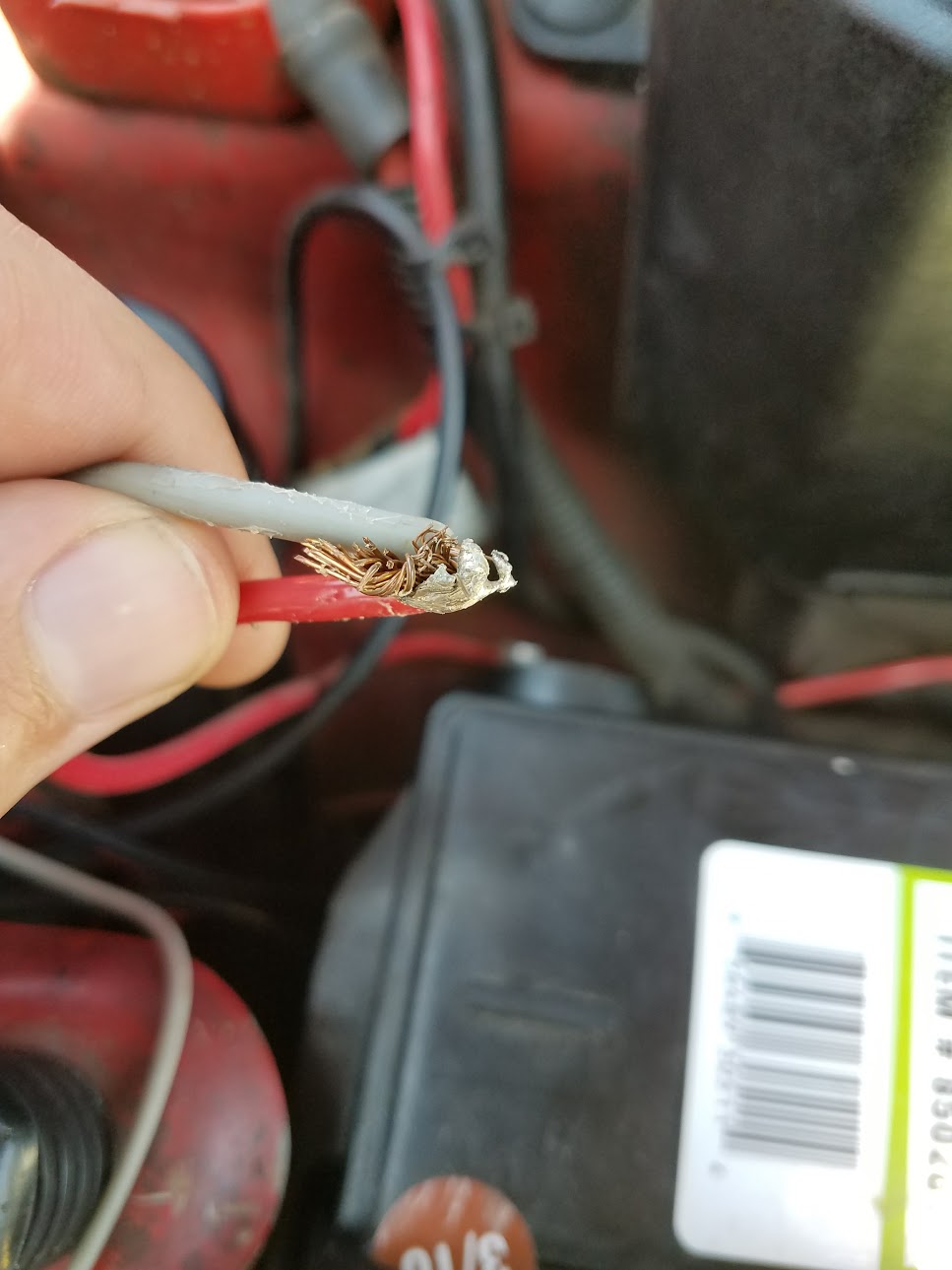
If you can pull the wire out you probably need to get a different set of crimpers. The heat shrink is not supposed to keep the wire from pulling out.
If you can pull the wire out of the butt connector you don't have a good crimp and you don't have a good/solid connection. You will have problems in that butt connector.
We do A LOT of wiring at work. Fixing other shops work and installing Holley EFI setups.
We don't solder anything. I've never seen solder in a race car, a properly built racecar anyway.
OP this is not directed at you. But out of all the things I see at work, fixing other shops and customers installs, wiring is the worst.
Improper connections, crimps, wire nuts, scotch locks......oh Lord the Scotch locks...
 07-23-2017, 10:40 PM
#31
LOL, I know you said it wasn't directed at met, but I hope you aren't shaking your head at my pictures. But I cranked down hard on my crimper, these wires do not slide at all.
07-25-2017, 08:22 PM
#33
God damn pump turned off today. I jiggled the harness then it immediately came back on. 
Anyone have any recommendations on a full replacement? This harness might just be better off starting over. I feel like my connections are solid but who knows what else is lurking I havnt found yet.
Maybe something like this?
https://www.summitracing.com/parts/prf-30132
Anyone have any recommendations on a full replacement? This harness might just be better off starting over. I feel like my connections are solid but who knows what else is lurking I havnt found yet.
Maybe something like this?
https://www.summitracing.com/parts/prf-30132
07-25-2017, 09:28 PM
#34
God damn pump turned off today. I jiggled the harness then it immediately came back on.
Anyone have any recommendations on a full replacement? This harness might just be better off starting over. I feel like my connections are solid but who knows what else is lurking I havnt found yet.
Maybe something like this?
https://www.summitracing.com/parts/prf-30132
Anyone have any recommendations on a full replacement? This harness might just be better off starting over. I feel like my connections are solid but who knows what else is lurking I havnt found yet.
Maybe something like this?
https://www.summitracing.com/parts/prf-30132
07-25-2017, 10:27 PM
#35
Maybe something like this?
https://www.summitracing.com/parts/prf-30132
https://www.summitracing.com/parts/prf-30132
07-26-2017, 01:07 PM
#36
Im sure it can be done, but I am looking for a more plug and play solution I guess. Not looking to custom make something. Just trying to do this quick. Unless you have suggestions on how to make my own easily? Just think this harness needs to be ripped out so there are no splices and all brand new connections.
07-26-2017, 01:38 PM
#37
Village Troll 
iTrader: (2)
This is becoming far too complicated. All you need is a 30A Bosch normally open relay and a $5.00 relay socket, and follow the wiring diagram. Even though it's not specifically CSR it is the exact same concept.
For the 12v constant, instead of running from the fuse box I ran it from the distribution block on the passenger fender. Ran it across and mounted the relay just below the underhood fuse box. For the switch wire I put a wire into the slot of the ABS fuse and mashed the fuse down on top of it. Pump won't come on until the key is on. Crimped loop terminals on the grounds and am using the bolt for the ground strap that goes from chassis to coil on the drivers side.
For the 12v constant, instead of running from the fuse box I ran it from the distribution block on the passenger fender. Ran it across and mounted the relay just below the underhood fuse box. For the switch wire I put a wire into the slot of the ABS fuse and mashed the fuse down on top of it. Pump won't come on until the key is on. Crimped loop terminals on the grounds and am using the bolt for the ground strap that goes from chassis to coil on the drivers side.
Last edited by SS RRR; 07-26-2017 at 01:44 PM.
07-26-2017, 03:51 PM
#38
while the above diagram is basically it...IMHO I would not run the +12v trigger wire by smashing it into a KO +12v circuit fuse. I would just splice it into that particular wire either solder it or use one of those "tap" connectors.
Put the circuit breaker or fuse inline to the +12v power to the EWP
Put the circuit breaker or fuse inline to the +12v power to the EWP
07-26-2017, 04:47 PM
#39
Village Troll
iTrader: (2)
Eh, I have multiple voltage sources smashed into fuse slots. Some of them have been that way for almost 20 years. There is no issue in doing so. I was going to tap a wire into the underhood fuse box, but I found it far less of a hassle to simply smash a wire. The water pump wire has been this way since 2007. No great shakes. Also, there should be an inline fuse already for power to the pump.
07-26-2017, 06:25 PM
#40
TECH Fanatic

while the above diagram is basically it...IMHO I would not run the +12v trigger wire by smashing it into a KO +12v circuit fuse. I would just splice it into that particular wire either solder it or use one of those "tap" connectors.
Put the circuit breaker or fuse inline to the +12v power to the EWP
Put the circuit breaker or fuse inline to the +12v power to the EWP