When you click on links to various merchants on this site and make a purchase, this can result in this site earning a commission. Affiliate programs and affiliations include, but are not limited to, the eBay Partner Network.
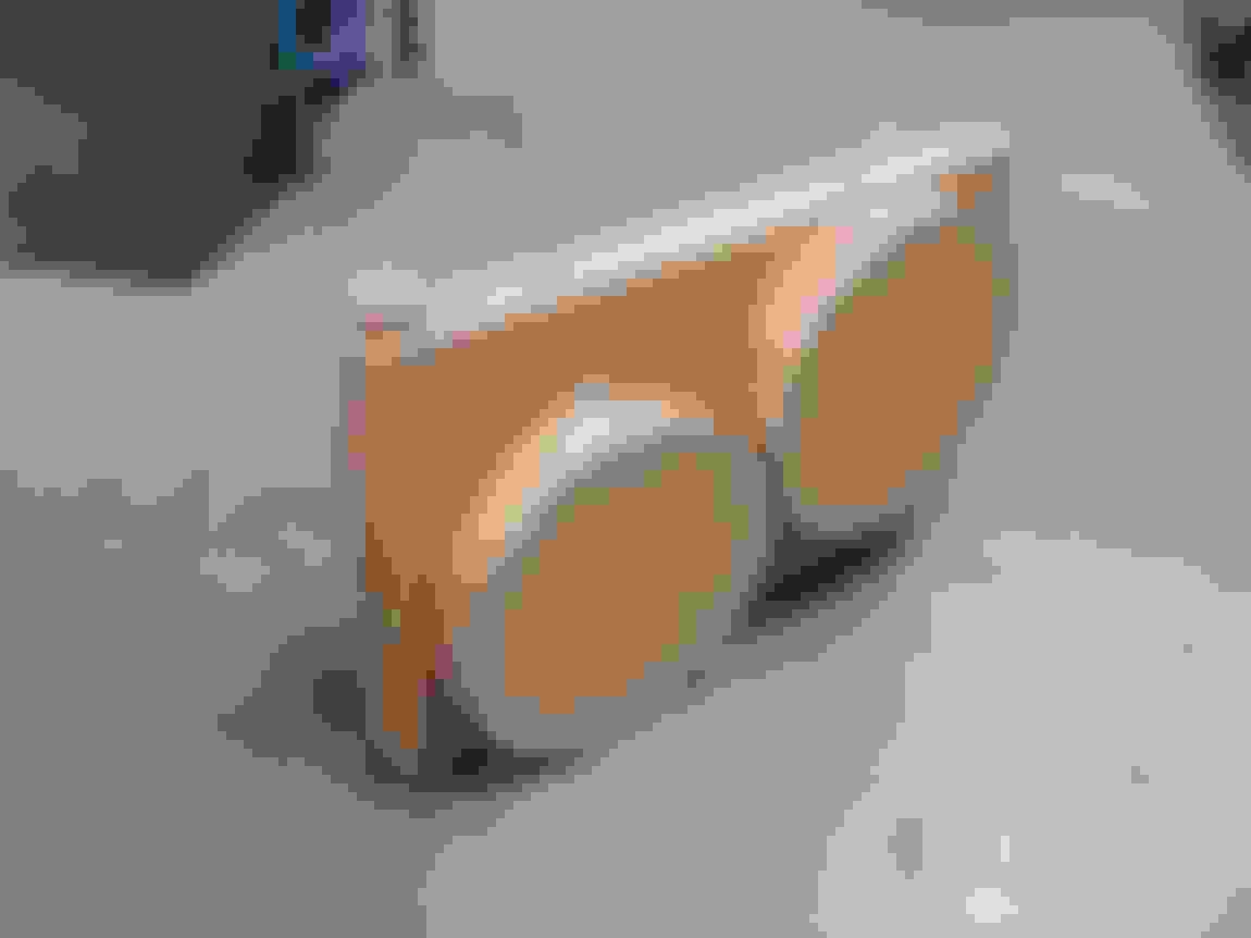
Made a mockup of the rad setup I was thinking of using.. a C&R 31" x 19" radiator, dual pass (inlet and outlet both on passenger side) which has the filler on the driver side. Along with dual 14" Derale fans that are ~2.75" deep.
I placed it on the old rad brackets just to see how high a 19" core would sit. Pretty up there, but the filler cap still clears the hood be 1/2". Think I'll lower it and see what the potential upper hose routing would look like.
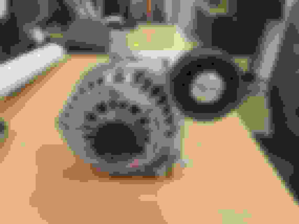
Also test fit the upper and lower alternator brackets before I drill and tap them to make a 3rd bridge piece, which will support the idler pulley. Fit is very good.. looks like my 3D model of the LS3 is accurate. There's about 3/8" gap between the alternator and the subframe cross member.. good thing I have the 1.5" further forward truck accessory drive or else the alternator in this location would for sure need to chopping of the subframe. The 1/4" adjustment I built into the brackets via slots works well, it visibly aligns the belt in plane when set up right in the middle of the slots.
Some more progress today.. used an angle grinder on the Nova for the first time since probably 2013! Started mocking up OEM inner fenders to see how much needs to be cut and modified. I think I'd rather start with them and modify than make inner fenders from scratch. I don't have an English wheel or anything for sheetmetal work so inner fenders from scratch would guaranteed look super ghetto.
I immediately chopped the battery tray closeout areas as I know I won't need those (I'll be extending the fenders down vertically).
So with the spring removed but the shock in place, this is full compression. Stupid car is too low!
Marked up a section to cut. I'm no sheetmetal guy, but this seems to be the most straightforward way to move the inner fender up, and retain some of the mounting points.
And inner fender jammed in place. I'll need to definitely do some more snipping. With the fender more or less in its proper place but just moved up ~1", there's really good tire clearance on the inboard sidewall, but the out the outboard sidewall is binding on the fender, so I'll have to cut that up.
Also cut out recesses for the clutch master and turbine housing, and see how well that lets me shift the inner fender some more. Luckily it looks like there's loads of room between the turbine housing and the tire inner sidewall at full lock, so I think a healthy recess for the turbo will work well.
Lastly, did a major clean and reorganize of the garage.. got everything off the floor except the floor jack and the 4 dollies holding the car up, so that felt nice. Not sure if I've shown before, but this is all the room I've been working with since 2004, other than the mill/lathe stuff I do at my work's machine shop, and maybe half the welding...
Pulling the fenders up 1" will necessitate adding to the outboard side to be able to bolt them to the outer fender. While you're in there you should try to reduce the amount of fender that kicks inboard at the outer mounts, especially at apex of the wheelwell; I pulled mine this weekend to clip some of the material being rubbed at full lock, and found it rubbing there, as well.
ETA: And replacing the hex head screws with button-heads. I believe they're 3/8"-16.
Last edited by hookemdevils22; 12-04-2017 at 10:55 AM.
Yeah I've actually already done that, I clipped the edge of the fender lip from 10 o'clock to 2 o'clock, when viewed from the side. I trimmed the lip from maybe 3/4" wide down to 1/8" wide, so now the tire rubs on the formed bend just above the lip area. I'll look for some pics of what I've done. Andyeah, the buttonhead is a good idea.
I think I'm going to end up trimming the inner fender right where it starts to be covered by the outer fender on the engine bay side, and make everything that's hidden be just a big cylindrical barrel for tire clearance. Extend that barrel laterally all the way to the inside face of the outer fender, then extend it down to the fender lip making it hug the outer fender as tight as possible. I've seen this mod before, but I can't remember which forum/thread.
Do you have your swaybar out? You might want to check for clearance for the alternator. I had to shim mine down to clear the AC compressor I put in that same location. Glad you have some space for it without cutting the frame. The brackets turned out great!
It currently doesn't have a swaybar, but I'll be making a custom one in the spring once the turbo piping and rad location are sorted out. I'll be putting the bar entirely in front of the accessory drive, and be notching the outsides of the subframe rails to clear the arms, such that the arms are more inboard than where the current subframe outside faces are, so that the arms have clearance to the tires at full lock.
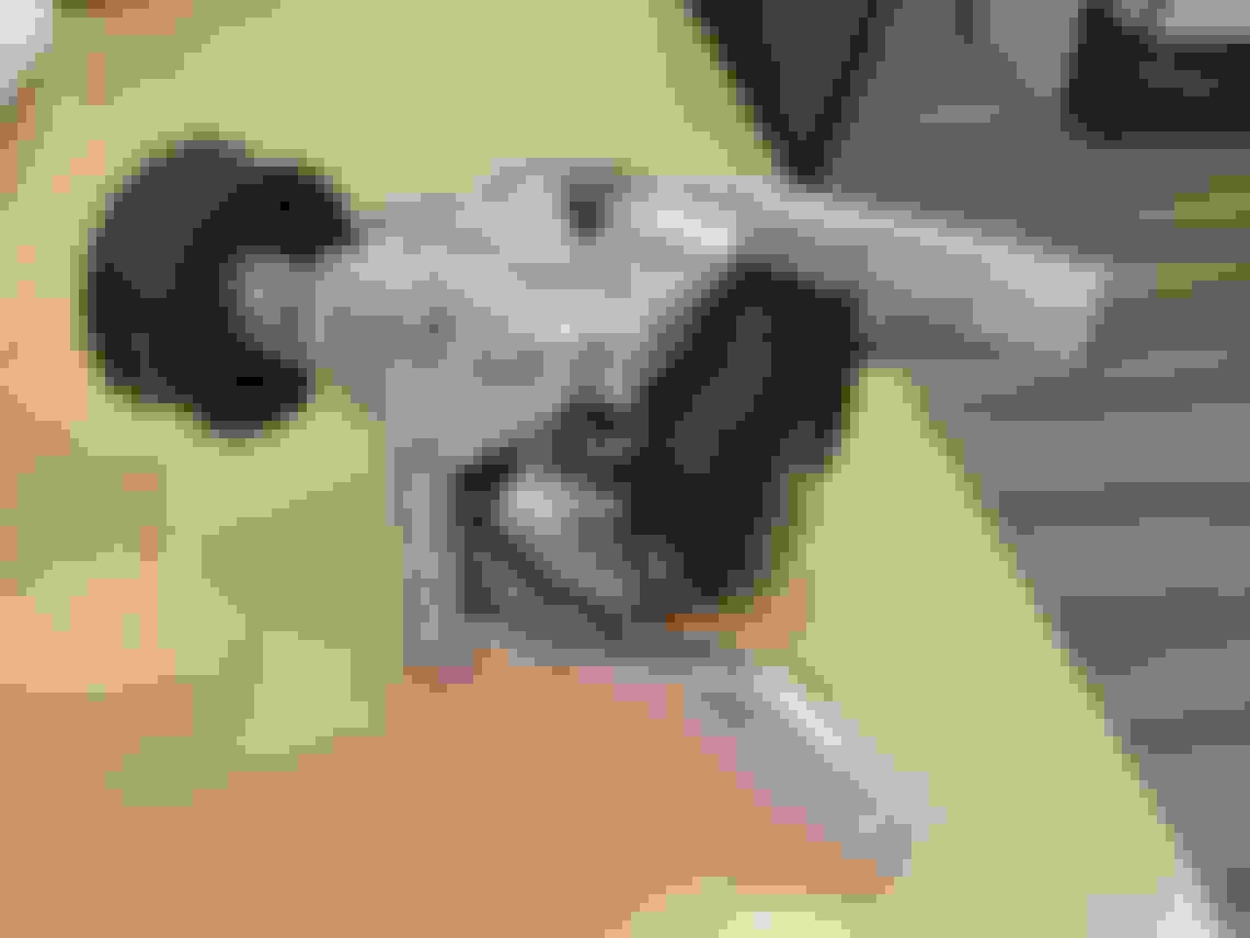
Alternator bracketry wrapped up and ready to install on car this weekend. I'll then pull the P/S pump bracket and trim it down since it no longer needs to support the alternator.
STILL waiting on the turbos.. I guess it's been less than 2 weeks but man are they hard to be patient for!
Test fit the alternator brackets.. they seem to fit well although I think the alternator redirect pulley might be spaced a tad too much forward, won't know for sure until there is a real belt on the drive under tension and the accessory drive has run for a couple revolutions.
Last step is to trim some of the fat off the previous P/S pump & alternator bracket. Eyeballed a new upper redirect pulley location, drilled and tapped the existing bracket, then quickly hacked off the unneeded remainder on the home bandsaw, and will finish mill the edges to look nicely in the shop at work.
Previously a banjo fitting on the P/S pump, wanted to move to a smoother-bend hose end. It's close but should fit, and open up some hose routing options around the pump.
I'll route it on the inboard side of the pump, and ziptie the hose to a standoff I'll add to a bracket to isolate the pressure hose and prevent it from rubbing on anything.
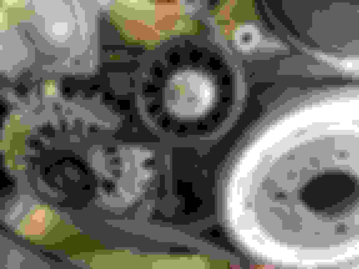
Quite stoked on the belt path.. in person it's very low slung and compact looking!...
Looks good. I wonder how well that tensioner will work in that location? Usually the spring type tensioners are the last in line to pull up the belt slack, but they don't have to resist the driving load from accessories. With your tensioner location, the belt will have the alternator load on it. You might want to convert that to a fixed adjustable tensioner.
Clint that's a good point.. to be honest it totally escaped my train of thought. The spring tensioner worked well when it had nothing it needed to pull, so I will see how this works in the beginning just to try out. I'm just not sure how it will work till I see it running.
Good to know, I'll keep an eye on it. Currently with pulleys on both sides of the crank pulley, there's no easy way to just move the spring tensioner to the "end of the line" slack side feeding back onto the crank pulley. So I'll just have to see how it goes.


 12-02-2017 | 09:45 PM