


Follow along with an engine build @ Weber Racing Engines!!
Thread Starter
Banned
iTrader: (4)
Joined: Jan 2007
Posts: 539
Likes: 0
From: North Ridgeville, Ohio
This is from a post that started in the Nitrous Section about a customers engine that we are building. We are doing a step by step follow along of all of the processes that ALL engines go threw here @ WRE. Here is what this build is going to consist of:
408 CI Iron Block
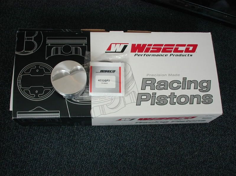
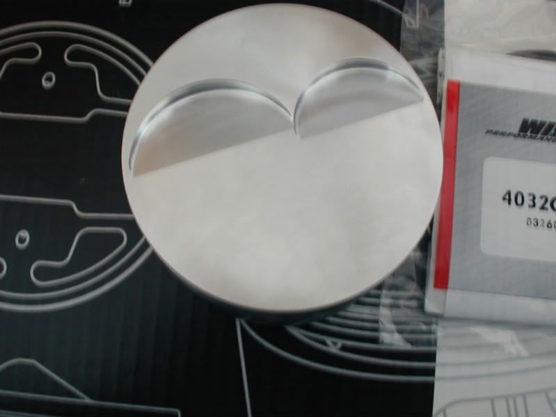
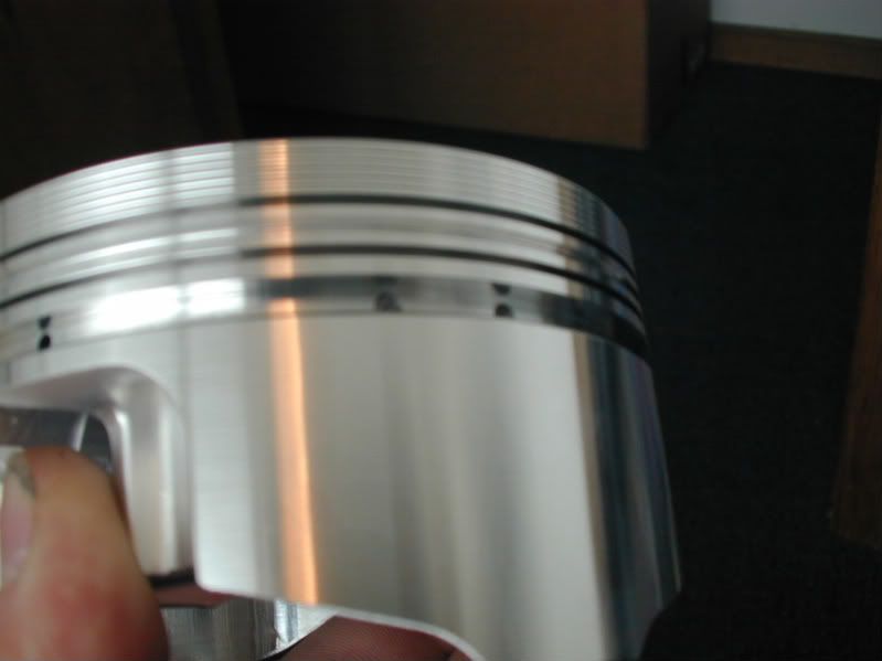
Custom Wiseco Flat Top Pistons
K1 Tech Connecting Rods
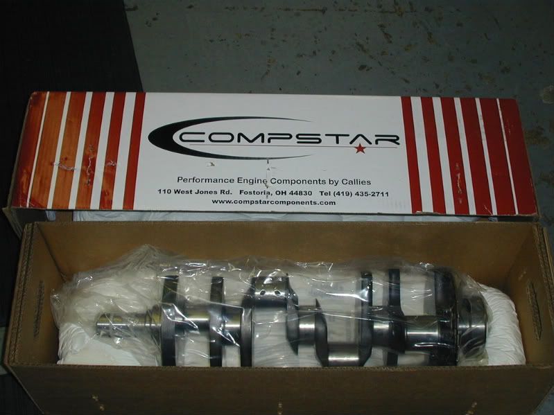
Callies Compstar Crankshaft
Solid Roller Camshaft
TEA/Trickflow 235cc CNC Ported Cylinder Heads
Now there will be a pause in production as we have custom pistons going threw for Andrew so we will have a gap in work. I will update as much as possible.
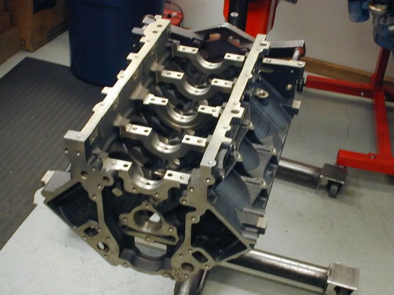
Obviouslly we have to start with a brand new GM Performance Parts 6.0L iron block:

Next the block is put in line for the CNC. A tag is put on it with the work order number. When the work order is pulled, the block is taken over and prepped to go on the CNC.


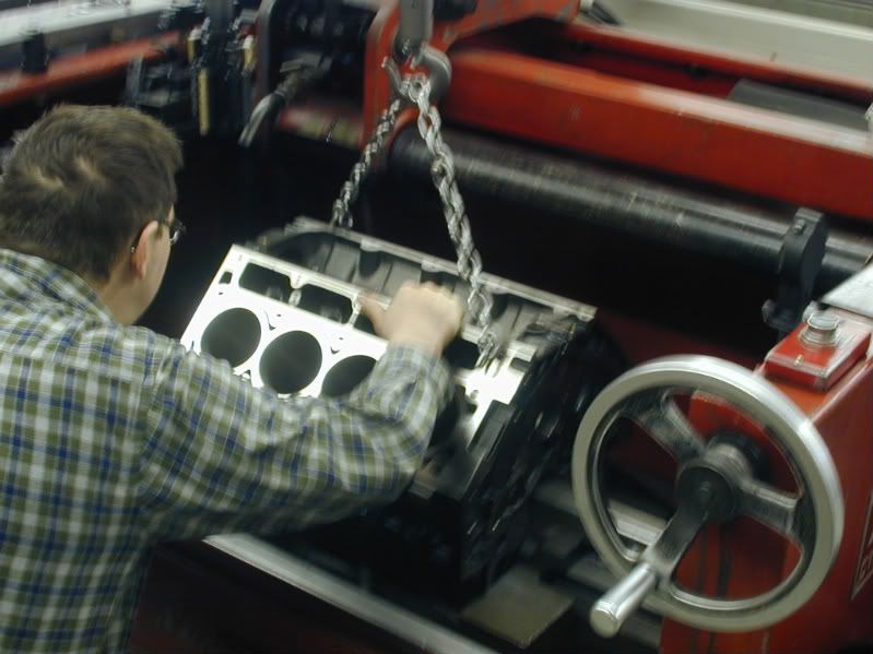
When the work order is pulled Greg, the CNC machinist picks the engine up on the overhead crane and takes it to the prep table to get it ready to mount in the CNC. Here is a picture of Greg removing sharp edges that are all over these new GM blocks. This is a very important step that we will talk about more later when the block is align honed. This is just a quick clean up.


Next Greg is removing the factory cam bearings. We will be replacing the factory cam bearing with 1 piece Durabond cam bearings later on.

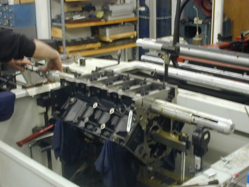
Here is the engine mounted to the fixture that it rides on in the CNC machine, the block is suspended on the chain from the overhead crane:

After the block is setup in the CNC and all measurements are taken and deck height is established the block is decked to the desired heigh ( Sorry I was on the phone with a customer when the measurments were taken, Ill have to get a picture on the next block that Greg gets in the CNC ).
Here is a picture of the the head coming across the deck to make a nice flat head gasket surface on the block.


Next the tools are changed in the machine and the cylinders are bored. Andrews motor is going to be 408 CI, so the finished bore size will end up at 4.030. In the CNC the block is bored to 4.027 leaving .003 for hone stock so we can hone to size with the torque plate. Only going .030 over we complete this in 2 runs through the cylinder, one rough cut, and one finish cut.

This is a picture on the first pass through the cylinder, you can see where the material is being taken out of the cylinder.

After the cylinders are bored to 4.027 we chamfer the cylinders. This helps guide ring installation when we are assembling the motors. ALso gets rid of sharp edges in the combustion chamber :
This is a picture of the top of the cylinder before we chamfer:

Here is a picture of the tool in the process of chamfering the cylinder:

You can see the cylinder to the left has already been chamfered:

Here is the finished product after the cylinder has been chamfered:

After the cylinders are chamfered we spray off all the chips with an air hose and take one last clean up pass on the deck with an abrasive brush that gives a good surface finish and deburs surface at the same time:


Well that is all for today. Tomorrow morning the block will be honed to size with a torque plate and setup in the align hone. Stay tuned!
408 CI Iron Block
Custom Wiseco Flat Top Pistons
K1 Tech Connecting Rods
Callies Compstar Crankshaft
Solid Roller Camshaft
TEA/Trickflow 235cc CNC Ported Cylinder Heads
Now there will be a pause in production as we have custom pistons going threw for Andrew so we will have a gap in work. I will update as much as possible.
Obviouslly we have to start with a brand new GM Performance Parts 6.0L iron block:
Next the block is put in line for the CNC. A tag is put on it with the work order number. When the work order is pulled, the block is taken over and prepped to go on the CNC.
When the work order is pulled Greg, the CNC machinist picks the engine up on the overhead crane and takes it to the prep table to get it ready to mount in the CNC. Here is a picture of Greg removing sharp edges that are all over these new GM blocks. This is a very important step that we will talk about more later when the block is align honed. This is just a quick clean up.
Next Greg is removing the factory cam bearings. We will be replacing the factory cam bearing with 1 piece Durabond cam bearings later on.
Here is the engine mounted to the fixture that it rides on in the CNC machine, the block is suspended on the chain from the overhead crane:
After the block is setup in the CNC and all measurements are taken and deck height is established the block is decked to the desired heigh ( Sorry I was on the phone with a customer when the measurments were taken, Ill have to get a picture on the next block that Greg gets in the CNC ).
Here is a picture of the the head coming across the deck to make a nice flat head gasket surface on the block.
Next the tools are changed in the machine and the cylinders are bored. Andrews motor is going to be 408 CI, so the finished bore size will end up at 4.030. In the CNC the block is bored to 4.027 leaving .003 for hone stock so we can hone to size with the torque plate. Only going .030 over we complete this in 2 runs through the cylinder, one rough cut, and one finish cut.
This is a picture on the first pass through the cylinder, you can see where the material is being taken out of the cylinder.
After the cylinders are bored to 4.027 we chamfer the cylinders. This helps guide ring installation when we are assembling the motors. ALso gets rid of sharp edges in the combustion chamber :
This is a picture of the top of the cylinder before we chamfer:
Here is a picture of the tool in the process of chamfering the cylinder:
You can see the cylinder to the left has already been chamfered:
Here is the finished product after the cylinder has been chamfered:
After the cylinders are chamfered we spray off all the chips with an air hose and take one last clean up pass on the deck with an abrasive brush that gives a good surface finish and deburs surface at the same time:
Well that is all for today. Tomorrow morning the block will be honed to size with a torque plate and setup in the align hone. Stay tuned!
Thread Starter
Banned
iTrader: (4)
Joined: Jan 2007
Posts: 539
Likes: 0
From: North Ridgeville, Ohio
Thread Starter
Banned
iTrader: (4)
Joined: Jan 2007
Posts: 539
Likes: 0
From: North Ridgeville, Ohio
Well its Friday! Thanks for the replies everyone. I was really hoping that everyone would enjoy and learn from this. We do this stuff everyday and really take it for granted. There is alot of work that goes into our engines as you will see in the rest of this post.
Well when I went back in the shop today Greg was just getting ready to take the block out of the CNC but first he stamped the in the deck height on the block. This way the customer knows where it is at. It is just something we do on every engine to take out guesswork later on.

Next the block was taken out of the CNC and out over on a bench where Shaun will debur the block. Deburring the block gets rid of all of the sharp edges that many of us have just about had to go to the hospital for when doing a head swap or something in the car. These blocks are razor sharp when they are new. There is also casting flash in the oil valley that we remove. This is a part of picking up where the production line leaves off.
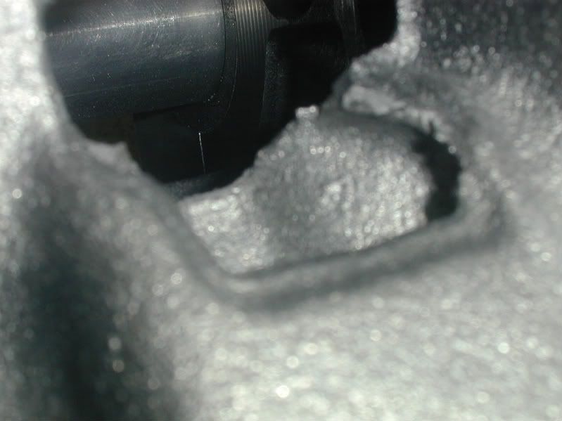
Here is a picture of the casting flash in the valley that will be removed:


Here is Shaun removing the burs from the block :

Here is one of the oil passages that he finished. This process usually takes about an hour to go through the block. You can not begin to see the value in the cost of a Weber Racing Engine!

After Shaun is done with the block, it will get hooked back onto the crane and put into the align hone to have the mains check and honed. This is also where the main caps will be detailed:

Well when I went back in the shop today Greg was just getting ready to take the block out of the CNC but first he stamped the in the deck height on the block. This way the customer knows where it is at. It is just something we do on every engine to take out guesswork later on.
Next the block was taken out of the CNC and out over on a bench where Shaun will debur the block. Deburring the block gets rid of all of the sharp edges that many of us have just about had to go to the hospital for when doing a head swap or something in the car. These blocks are razor sharp when they are new. There is also casting flash in the oil valley that we remove. This is a part of picking up where the production line leaves off.
Here is a picture of the casting flash in the valley that will be removed:
Here is Shaun removing the burs from the block :
Here is one of the oil passages that he finished. This process usually takes about an hour to go through the block. You can not begin to see the value in the cost of a Weber Racing Engine!
After Shaun is done with the block, it will get hooked back onto the crane and put into the align hone to have the mains check and honed. This is also where the main caps will be detailed:
Trending Topics
LS1 Tech Stories
The Best V8 Stories One Small Block at Time

Topdon ONE vs. Artidiag 800 BT2: Which is the Diagnostic Tablet For You?
Pouria Savadkouei
Gas Monkey Built a 6-Wheel Ferrari Testarossa With a Corvette LT4 Engine
Verdad Gallardo
7 Most Reliable High-Performance Engines GM Has Ever Built
Verdad Gallardo
Amazing '71 Camaro Restomod Is Modern Muscle Car Under the Skin
Verdad Gallardo
6 Common C5 Corvette Failures and What's Involved In Repairing Them
Pouria Savadkouei
Retro Modern Bandit Pontiac Trans AM Comes With Burt Reynolds' Autograph
Verdad Gallardo
Top 10 Greatest Cadillac V Series Performance Models Ever, Ranked
Pouria Savadkouei
Top 10 Most Powerful Chevy Trucks Ever Made!

Hennessey's New Supercharged Silverado ZR2 Has 700 HP
Verdad Gallardo
Thread Starter
Banned
iTrader: (4)
Joined: Jan 2007
Posts: 539
Likes: 0
From: North Ridgeville, Ohio
Now the block is hooked back up to the crane and lowered into the align hone where Greg fastens it down.


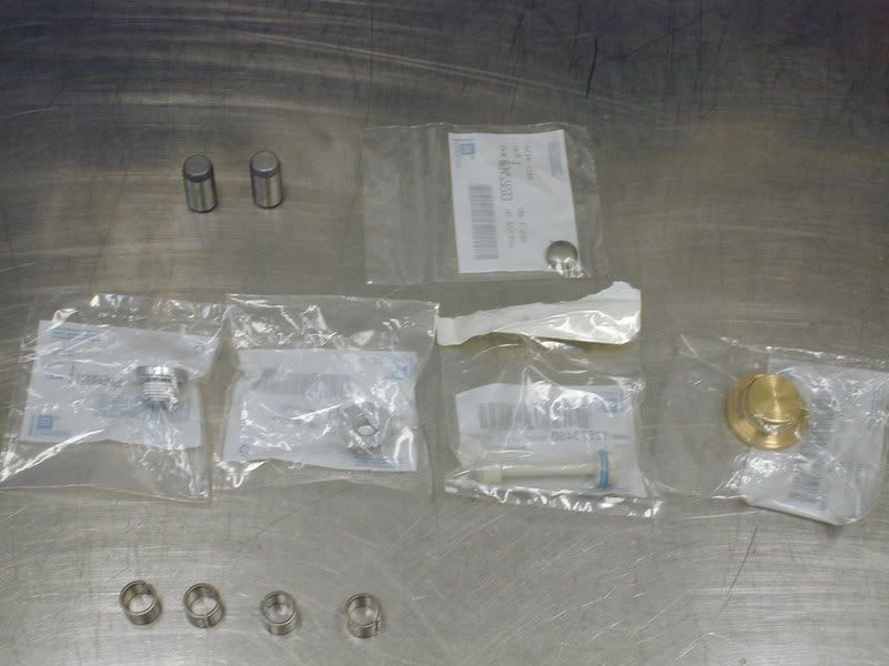
Here are the ARP main studs that will be used in the block to hold down the main caps.

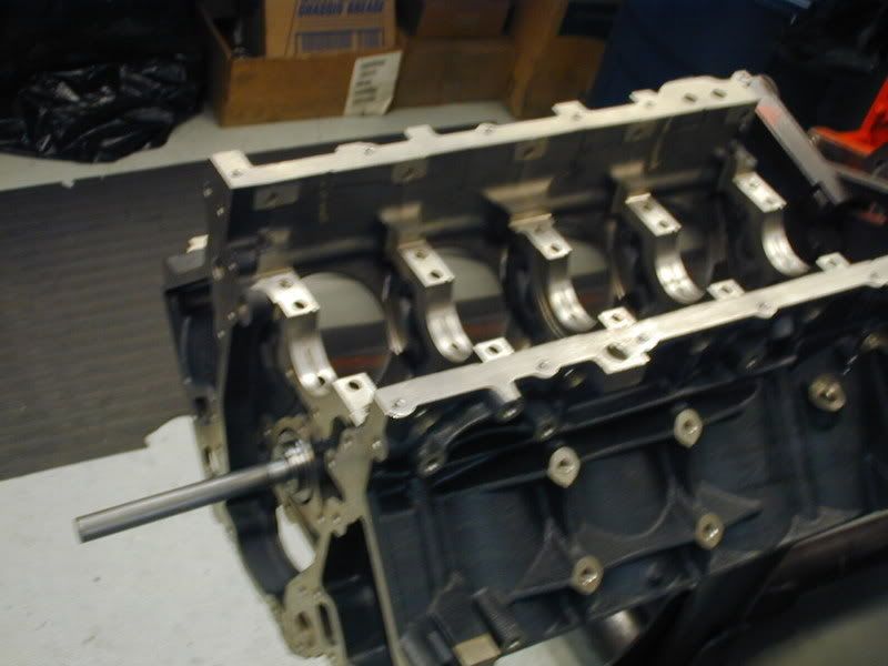
Here is a picture of the main studs installed in the block before the main caps are put on:

Greg first torques all of the caps in sequence and to spec:

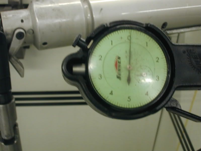
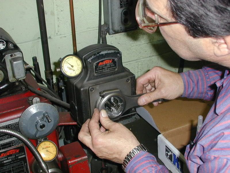
Greg than inserts a dial bore gauge into the rear main cap to check the diameter. The dial bore gauge is set to the max allowed bore size :

Now this is a perfect reason of what we do what we do and why we do it! This is a brand new block from GM. After installing the studs the main cap was measured and shows .001 over the high limit! Remember this gauge is set to the high limit. We can go as much as .001 smaller (to the right of the 0), but do not want to go bigger (to the left of the 0). There is more to this and much more precise figures, but this gives you a general idea. :

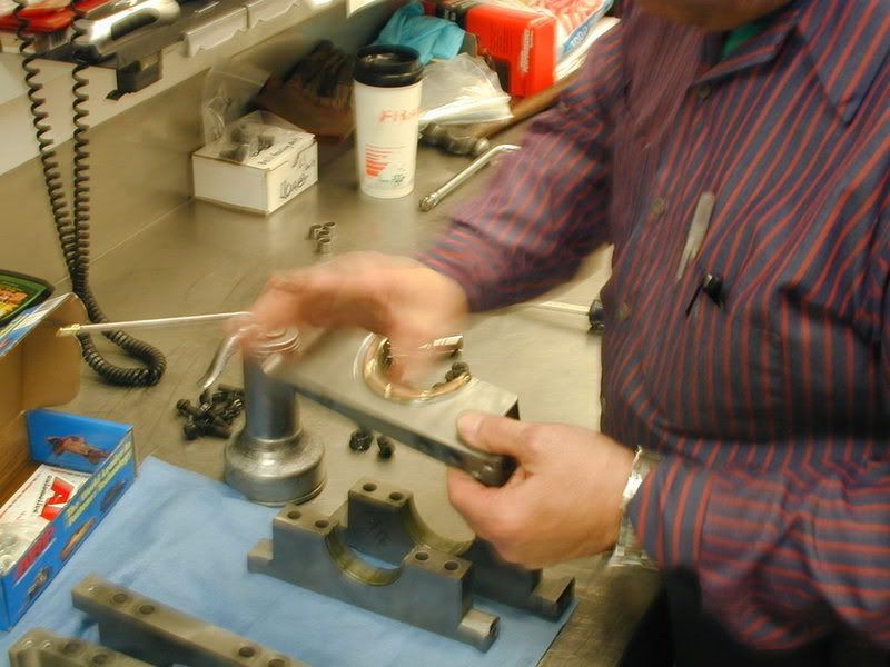
Here is the main cap after Greg takes it off the block. He is not going to take this main cap over to the Sunnen Cap and Rod grinder and will take very very small swipes off of the bottom of the main cap to bring it within tolerance. The cap is fixtured into this machine and is run back and forth to take small swipes at the surface. Inside the machine is basically a grinding wheel with a light abrasive pad on it to take precision and clean cuts at the part you are working on:
Here is a pic of the main cap when it is taken off the block before we machine it:

Greg machining the cap in the Sunnen Cap and Rod grinder:

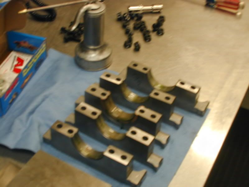
here is a picture of the cap after it comes out. Notice the cross hatching is gone and there is a nice and smooth and shiny surface. In person you can really see the difference. Unfortunately my camera cannot pickup everything and allow you to really feel the difference on the cap.:

Greg than repeats the last step on a couple other caps. The caps are than reinstalled and the align hone is ran through the caps.:


After the hone is ran through the caps and they are taken off again to be cleaned up we come up with a measurement we are looking for:
This is a very long process of trial and error. You never want to take too much off so there is alot of test fitting and measuring that goes on. This may help some people why an align hone is such an expensive task. There is ALOT of time and materials wrapped up in this. Having a qualified machinist such as Greg does help alot on knowing just how much to take off and what procedures work.
Next the block is going to be moved over to the Sunnen CK-10 Cylinder King Cylinder Hone to hone the bores to size.
As I am typing this it is 3:15 on Friday and Greg is finishing detailing all of the caps making sure they are perfect. It is quitting time @ 5:00. We may not have enough time to get the motor in the cylinder hone today, so we may leave ya hanging until next week!
Here are the ARP main studs that will be used in the block to hold down the main caps.
Here is a picture of the main studs installed in the block before the main caps are put on:
Greg first torques all of the caps in sequence and to spec:
Greg than inserts a dial bore gauge into the rear main cap to check the diameter. The dial bore gauge is set to the max allowed bore size :
Now this is a perfect reason of what we do what we do and why we do it! This is a brand new block from GM. After installing the studs the main cap was measured and shows .001 over the high limit! Remember this gauge is set to the high limit. We can go as much as .001 smaller (to the right of the 0), but do not want to go bigger (to the left of the 0). There is more to this and much more precise figures, but this gives you a general idea. :
Here is the main cap after Greg takes it off the block. He is not going to take this main cap over to the Sunnen Cap and Rod grinder and will take very very small swipes off of the bottom of the main cap to bring it within tolerance. The cap is fixtured into this machine and is run back and forth to take small swipes at the surface. Inside the machine is basically a grinding wheel with a light abrasive pad on it to take precision and clean cuts at the part you are working on:
Here is a pic of the main cap when it is taken off the block before we machine it:
Greg machining the cap in the Sunnen Cap and Rod grinder:
here is a picture of the cap after it comes out. Notice the cross hatching is gone and there is a nice and smooth and shiny surface. In person you can really see the difference. Unfortunately my camera cannot pickup everything and allow you to really feel the difference on the cap.:
Greg than repeats the last step on a couple other caps. The caps are than reinstalled and the align hone is ran through the caps.:
After the hone is ran through the caps and they are taken off again to be cleaned up we come up with a measurement we are looking for:
This is a very long process of trial and error. You never want to take too much off so there is alot of test fitting and measuring that goes on. This may help some people why an align hone is such an expensive task. There is ALOT of time and materials wrapped up in this. Having a qualified machinist such as Greg does help alot on knowing just how much to take off and what procedures work.
Next the block is going to be moved over to the Sunnen CK-10 Cylinder King Cylinder Hone to hone the bores to size.
As I am typing this it is 3:15 on Friday and Greg is finishing detailing all of the caps making sure they are perfect. It is quitting time @ 5:00. We may not have enough time to get the motor in the cylinder hone today, so we may leave ya hanging until next week!
Thread Starter
Banned
iTrader: (4)
Joined: Jan 2007
Posts: 539
Likes: 0
From: North Ridgeville, Ohio
Sorry for the delay everyone. We are having connectivity problems with the internet at the shop. We switched our voice over IP lines over the weekend and something was messed up. We should have this fixed by noon tomorrow. As soon as it is fixed I will be sure to update!
Thanks,
Leo
Thanks,
Leo
Thread Starter
Banned
iTrader: (4)
Joined: Jan 2007
Posts: 539
Likes: 0
From: North Ridgeville, Ohio
Sorry for the delay everyone. We finally got our internet back and running better than ever. For the past 2 days the download rate was only 38 kbps. I guess we are getting spoiled with high speed. The uploads of the pictures was near impossible so I was not able to update the thread. But nonetheless here we are.
After the block comes out of the align hone it is taken over to the Sunnen Cylinder Hone. Usually the block would come to the cylinder hone first but we had a job setup over there that changed the flow of things a little bit.
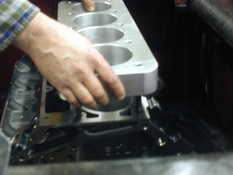
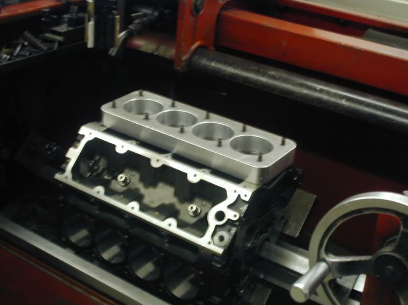
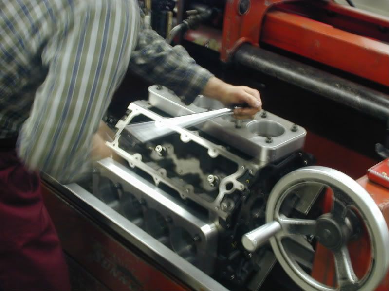
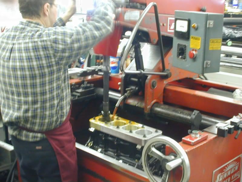
Here is a picture of Greg setting the block in the honing machine:
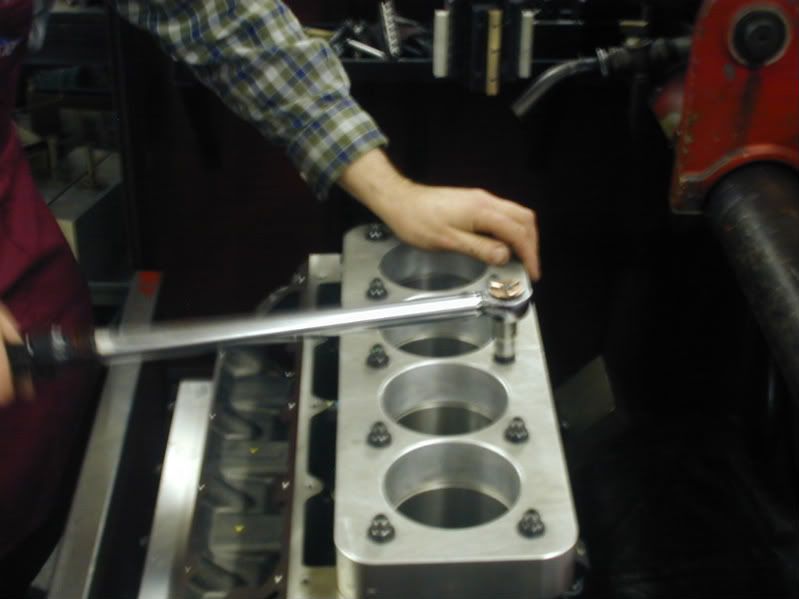
After the block is secure in the hone, head studs are installed and the torque plates are installed and torqued:
After the torque plates are installed the bores are checked for size. We use the same type of dial bore gauge that was used on the mains. I was pretty busy and running back and forth so I did not get a picture of Greg measuring the bores.
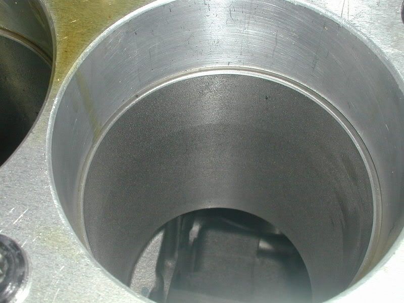
Here is the bore with the torque plate installed and the finish before we hone the bore:
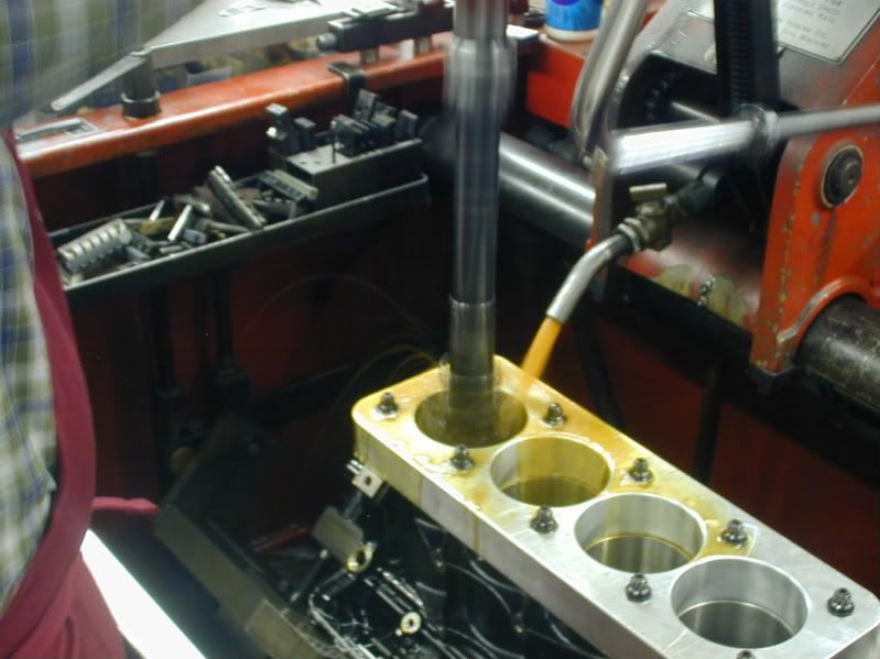
Here is Greg running the hone through the cylinder:
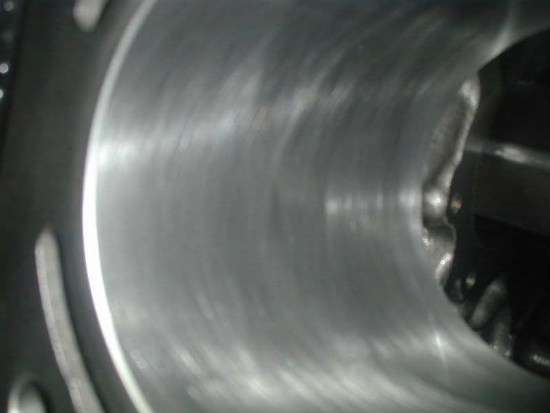
Now the ring finish and final product after the honing process is complete:
Now that the machining to the block is complete it will go over and get in line to be jet washed, dried and bagged to await assembly.
We are still waiting for the pistons and at the last minute changed to a solid roller camshaft. So we had to change the order in the heads. The guys at TEA are getting the heads done and we should have them when the custom pistons arrive in the first week of April.
Once the crankshaft, connecting rods and pistons are here I will be showing how the rotating assembly is balanced. After everything is balanced it is on to the assembly room where we end up with a completed engine. So STAY TUNED and please feel free to keep posting.pming/emailing your questions, comments and quote requests!
Thanks,
Leo
After the block comes out of the align hone it is taken over to the Sunnen Cylinder Hone. Usually the block would come to the cylinder hone first but we had a job setup over there that changed the flow of things a little bit.
Here is a picture of Greg setting the block in the honing machine:
After the block is secure in the hone, head studs are installed and the torque plates are installed and torqued:
After the torque plates are installed the bores are checked for size. We use the same type of dial bore gauge that was used on the mains. I was pretty busy and running back and forth so I did not get a picture of Greg measuring the bores.
Here is the bore with the torque plate installed and the finish before we hone the bore:
Here is Greg running the hone through the cylinder:
Now the ring finish and final product after the honing process is complete:
Now that the machining to the block is complete it will go over and get in line to be jet washed, dried and bagged to await assembly.
We are still waiting for the pistons and at the last minute changed to a solid roller camshaft. So we had to change the order in the heads. The guys at TEA are getting the heads done and we should have them when the custom pistons arrive in the first week of April.
Once the crankshaft, connecting rods and pistons are here I will be showing how the rotating assembly is balanced. After everything is balanced it is on to the assembly room where we end up with a completed engine. So STAY TUNED and please feel free to keep posting.pming/emailing your questions, comments and quote requests!
Thanks,
Leo
Thread Starter
Banned
iTrader: (4)
Joined: Jan 2007
Posts: 539
Likes: 0
From: North Ridgeville, Ohio
Ok everybody we are back to working on this engine. There was a good break in there due to some changes in the build. The day we started this thread we decided to go solid roller and the guys at TEA had to put together a custom solid roller setup set of 235cc Trickflow cylinder heads. Since we knew the heads would be a little bit and we were also waiting on the custom Wiseco pistons we took a break to get some other projects completed and out the door.
Now that the block is complete it went into the jet washer and was cleaned and bagged to wait in line for the assembly room. Unfortunatly I missed this part, but really there is nothing to see there. The block is in the jet washer and blown out with an air gun so it does not rust.
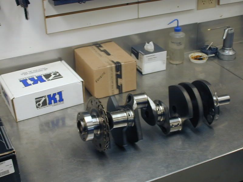
We have everything here for the rotating assembly to be balanced.
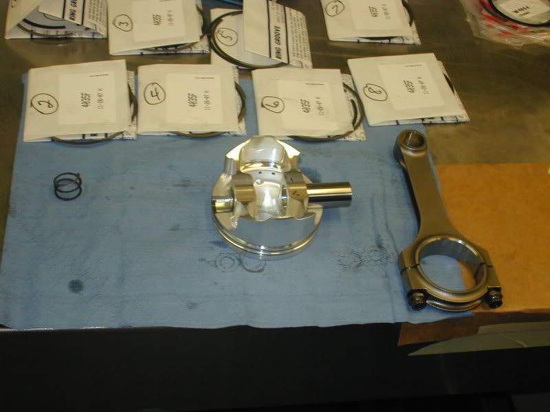
Here are the custom pistons from Wiseco:
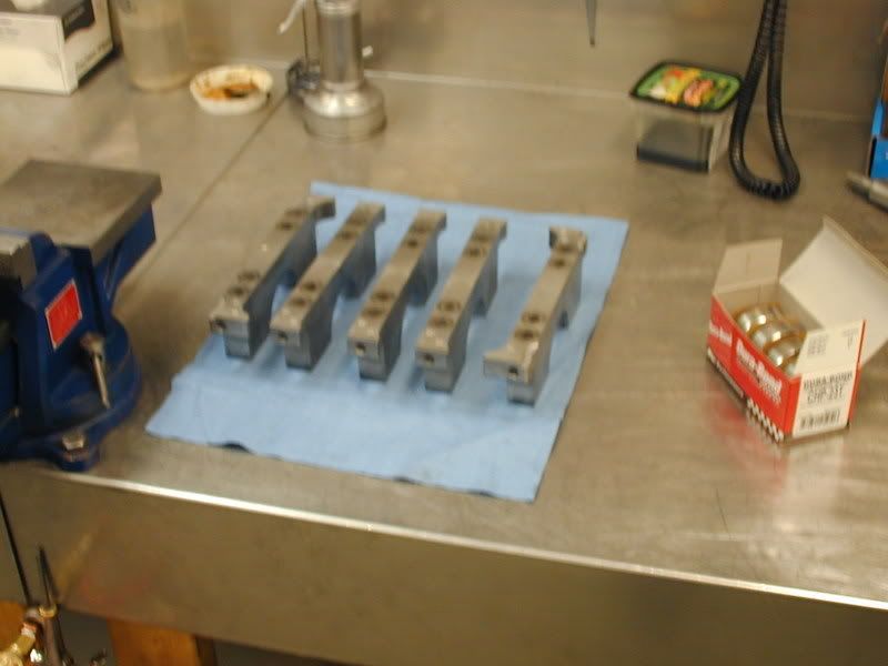
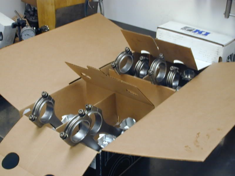
The K1 Tech Connecting Rods (Which you will see pictures of later.)
Callies Compstar 4.000 Stroke Crankshaft
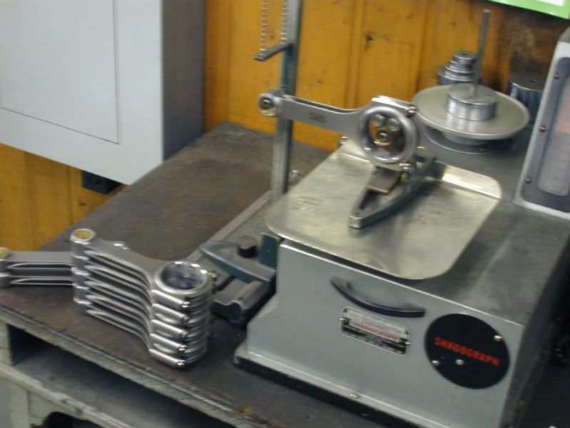
Everything is taken over the weigh station where Dave Weber will get rod, piston, ring and connecting rod weights to establish a bobweight so he can balance the crankshaft.
This is how the big end of the crank is weighed:
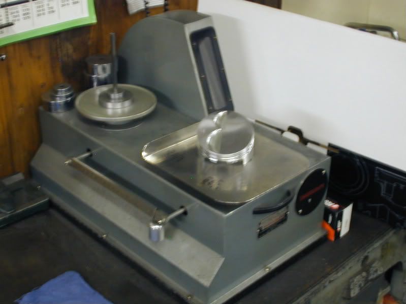
The pistons:
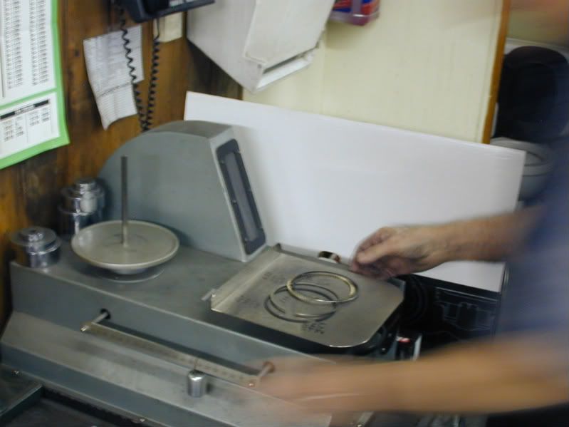
Piston Rings:
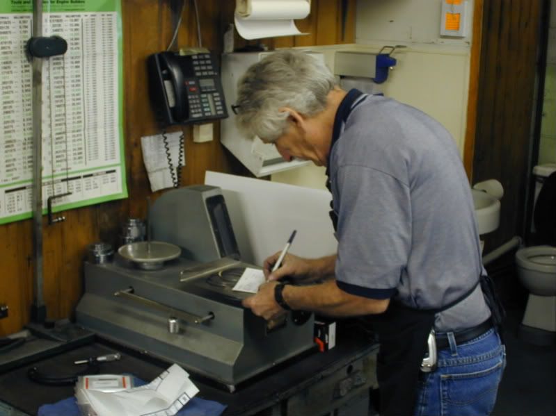
The rod bearings are also weighed and weights are recorded on a balance card that is kept on file:
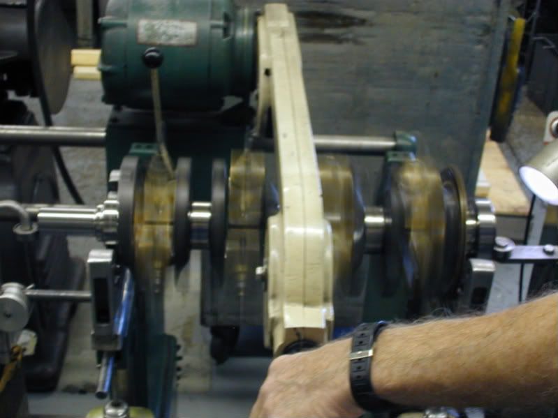
Next Dave sets up the crankshaft in the balancer with bobweights attached. When a crank is balanced it should sit in the balancer and not want to spin on its own at any point. There is alot more to balancing that I am not going to get into here. The bottom line is the crankshaft needs to be balanced so the engine will not vibrate and create harmonics and the engine to vibrate. This ensures a smooth running engine.
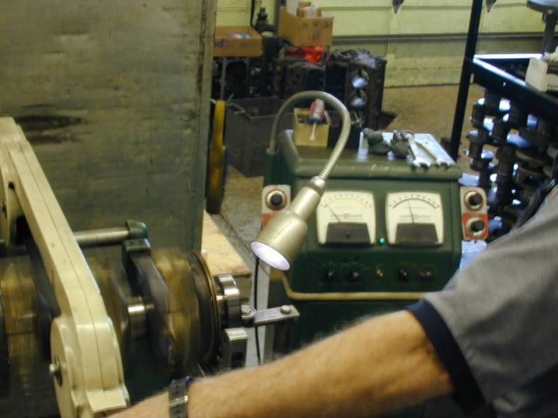
Here is a picture of Dave spinning the crankshaft on the balancer. While the crankshaft is spinning Dave is looking at the gauges to detect any loads that would detect the crank being out of balance.
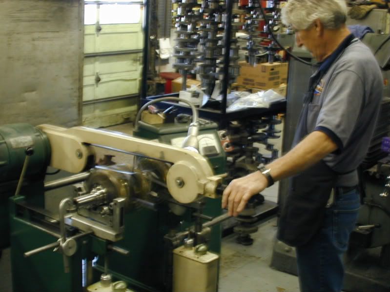
Even though these cranks are rough balanced, they still are not perfect. This one was off quite a bit. Dave than adds clay to the counter weights on the crankshaft. This clay is added and removed until a perfect balance is found.The clay is than weighed so we can see how much weight may need to be added or subtracted from the throws of the crank. This one needed some weight taken out.
When the weight is taken out of the crank by drilling into the counterweights of the crankshaft. Sorry I missed this part so do no have any pics of it. I will try to catch Dave working on another crank and get a pic for everyone to see.
Now that the block is complete it went into the jet washer and was cleaned and bagged to wait in line for the assembly room. Unfortunatly I missed this part, but really there is nothing to see there. The block is in the jet washer and blown out with an air gun so it does not rust.
We have everything here for the rotating assembly to be balanced.
Here are the custom pistons from Wiseco:
The K1 Tech Connecting Rods (Which you will see pictures of later.)
Callies Compstar 4.000 Stroke Crankshaft
Everything is taken over the weigh station where Dave Weber will get rod, piston, ring and connecting rod weights to establish a bobweight so he can balance the crankshaft.
This is how the big end of the crank is weighed:
The pistons:
Piston Rings:
The rod bearings are also weighed and weights are recorded on a balance card that is kept on file:
Next Dave sets up the crankshaft in the balancer with bobweights attached. When a crank is balanced it should sit in the balancer and not want to spin on its own at any point. There is alot more to balancing that I am not going to get into here. The bottom line is the crankshaft needs to be balanced so the engine will not vibrate and create harmonics and the engine to vibrate. This ensures a smooth running engine.
Here is a picture of Dave spinning the crankshaft on the balancer. While the crankshaft is spinning Dave is looking at the gauges to detect any loads that would detect the crank being out of balance.
Even though these cranks are rough balanced, they still are not perfect. This one was off quite a bit. Dave than adds clay to the counter weights on the crankshaft. This clay is added and removed until a perfect balance is found.The clay is than weighed so we can see how much weight may need to be added or subtracted from the throws of the crank. This one needed some weight taken out.
When the weight is taken out of the crank by drilling into the counterweights of the crankshaft. Sorry I missed this part so do no have any pics of it. I will try to catch Dave working on another crank and get a pic for everyone to see.
Thread Starter
Banned
iTrader: (4)
Joined: Jan 2007
Posts: 539
Likes: 0
From: North Ridgeville, Ohio
Well we have been SWAMPED. We were waiting on the new Crane Roller Rockers to arrive, which they finally have. The cam, heads and intake have all arrive. The intake which was plumbed by Nitrous Outlet has been disassembled to be ported. Sorry I did not get any pics before it was taken apart, but will be put back together as soon as the porting is completed.
So to continue.........................
After balancing all of the parts are brought into the engine assembly room and setup for short block assembly.

Once everything is organized Jim proceeds to install the cam bearings.
After the cam bearings are installed our "test: cam is installed to make sure there is no binding in the cam tunnel:
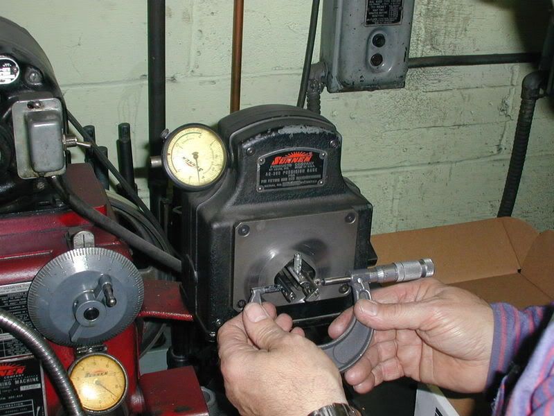
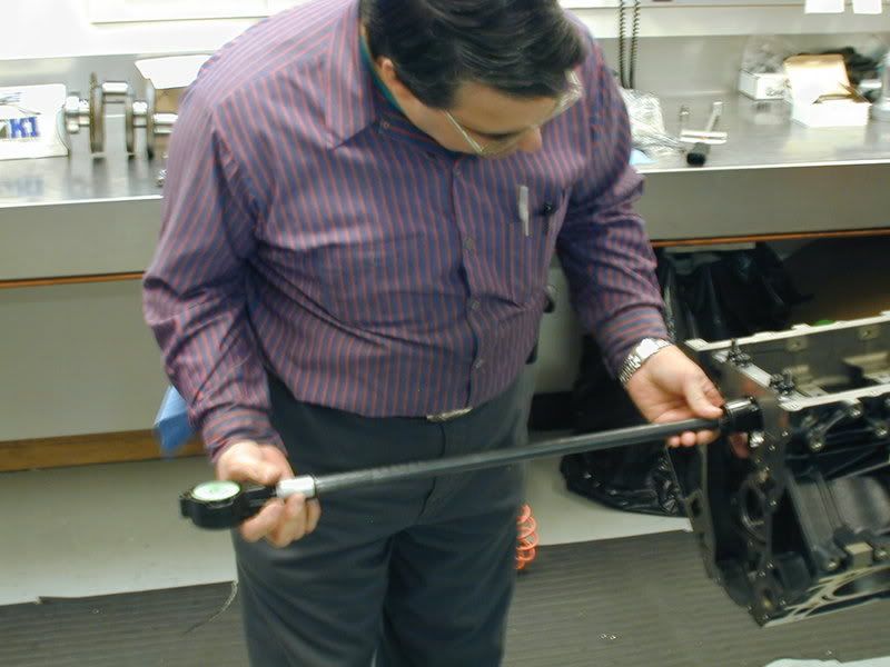
Next Jim is going to check the big end of the connecting rods for proper bore size. Even though these are new rods, we always double check the manufacturers work to make sure it meets our requirements. The rods are torqued as they would be installed and than are taken over to the Sunnen Rod Hone Machine to check size.
Here is a picture of Jim setting the micrometer for the big end diameter, than checking the rod on the Sunnen Rod Hone machine.
Next Jim goes back to the assembly room to check the main bearing ID. The main bearings are installed, the main cap is torqued and measured with a dial bore gauge.
The size of the mains are recorded and than Jim moves on to crankshaft to measure the O.D. on the main journals.
Between the 2 measurements we subtract the size of the crankshaft from the ID of the Main Cap and that give us our bearing clearance. Since we machine the blocks in house our tolerances are right in spec 99.9% of the time. If there is an issue at this point, we can use an over or under size bearing to make up for any clearance issues.
Next the main bearings are coated in a thin layer of oil and crankshaft thoroughly cleaned and is laid into the block:
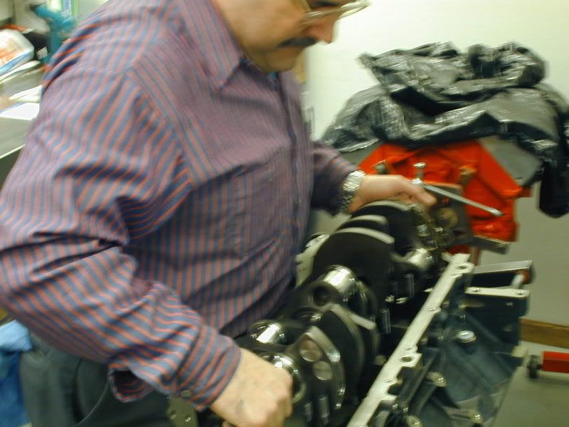
Next the main caps are oiled, installed and torqued to specification:
After that we test spin the crank to make sure there is no binding. We also check the end thrust to make sure it is within allowed tolerances. Once that is verified, its on to assembling the pistons and connecting rods.
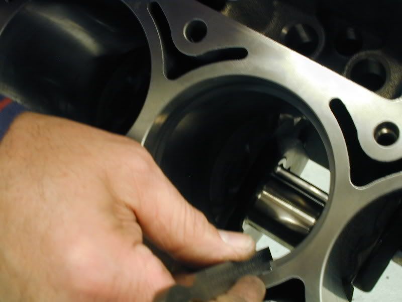
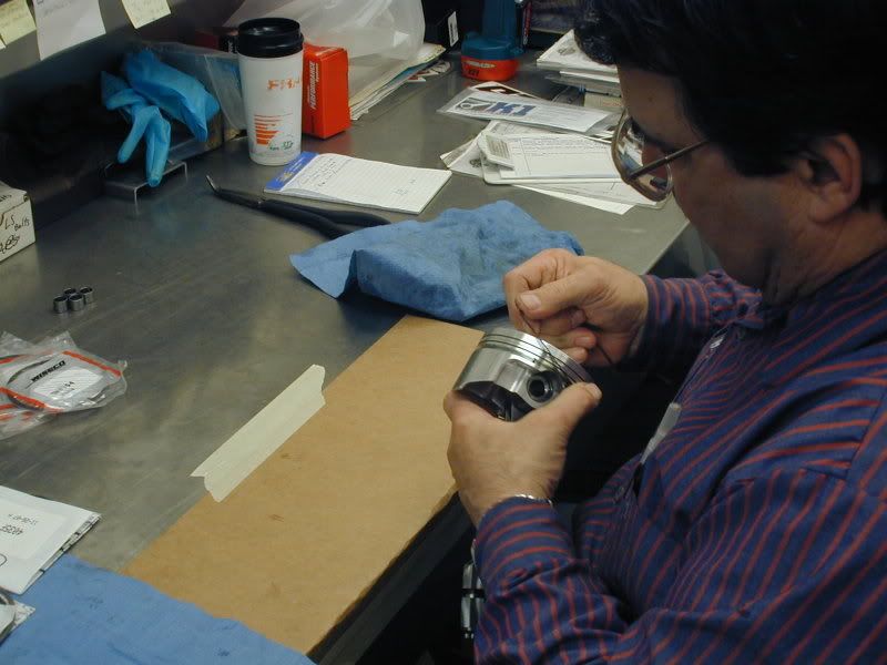
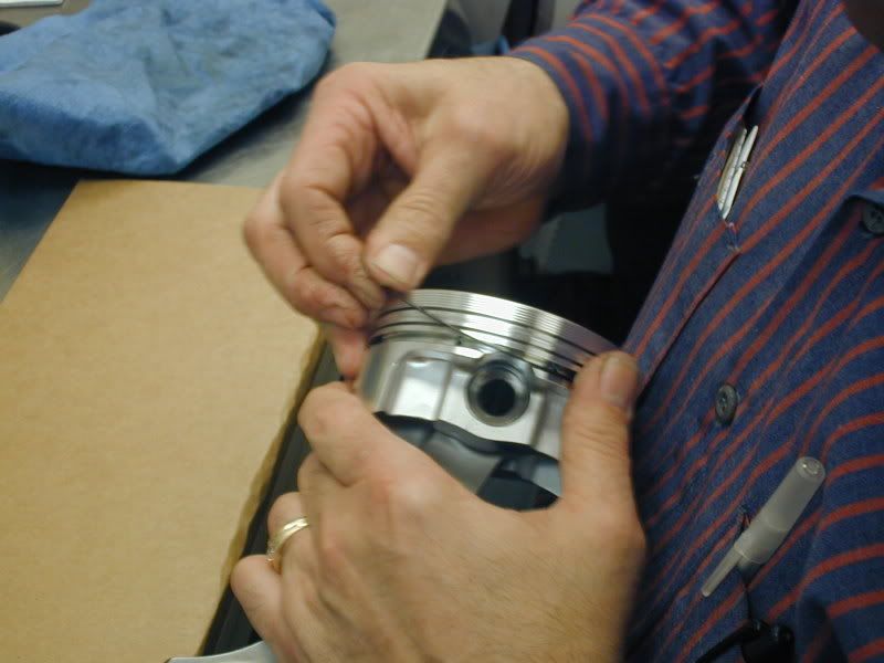
The first part of assembling the piston and rod assemblies the rings need to be gapped.
The rings are fit into the bore and measured with a taper gauge to check for proper ring gap. The ring has to be test fitted first to establish a starting point to see how much material needs to be removed to establish desired ring gap. This can vary from engine to engine depending on the use and power adders being used on the engine.
Jim checking the ring gap:
So to continue.........................
After balancing all of the parts are brought into the engine assembly room and setup for short block assembly.
Once everything is organized Jim proceeds to install the cam bearings.
After the cam bearings are installed our "test: cam is installed to make sure there is no binding in the cam tunnel:
Next Jim is going to check the big end of the connecting rods for proper bore size. Even though these are new rods, we always double check the manufacturers work to make sure it meets our requirements. The rods are torqued as they would be installed and than are taken over to the Sunnen Rod Hone Machine to check size.
Here is a picture of Jim setting the micrometer for the big end diameter, than checking the rod on the Sunnen Rod Hone machine.
Next Jim goes back to the assembly room to check the main bearing ID. The main bearings are installed, the main cap is torqued and measured with a dial bore gauge.
The size of the mains are recorded and than Jim moves on to crankshaft to measure the O.D. on the main journals.
Between the 2 measurements we subtract the size of the crankshaft from the ID of the Main Cap and that give us our bearing clearance. Since we machine the blocks in house our tolerances are right in spec 99.9% of the time. If there is an issue at this point, we can use an over or under size bearing to make up for any clearance issues.
Next the main bearings are coated in a thin layer of oil and crankshaft thoroughly cleaned and is laid into the block:
Next the main caps are oiled, installed and torqued to specification:
After that we test spin the crank to make sure there is no binding. We also check the end thrust to make sure it is within allowed tolerances. Once that is verified, its on to assembling the pistons and connecting rods.
The first part of assembling the piston and rod assemblies the rings need to be gapped.
The rings are fit into the bore and measured with a taper gauge to check for proper ring gap. The ring has to be test fitted first to establish a starting point to see how much material needs to be removed to establish desired ring gap. This can vary from engine to engine depending on the use and power adders being used on the engine.
Jim checking the ring gap:
Thread Starter
Banned
iTrader: (4)
Joined: Jan 2007
Posts: 539
Likes: 0
From: North Ridgeville, Ohio
Next the rings are filed to size on the piston ring filer:
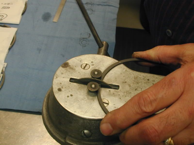
This process is repeated until the desired ring gap is achieved.
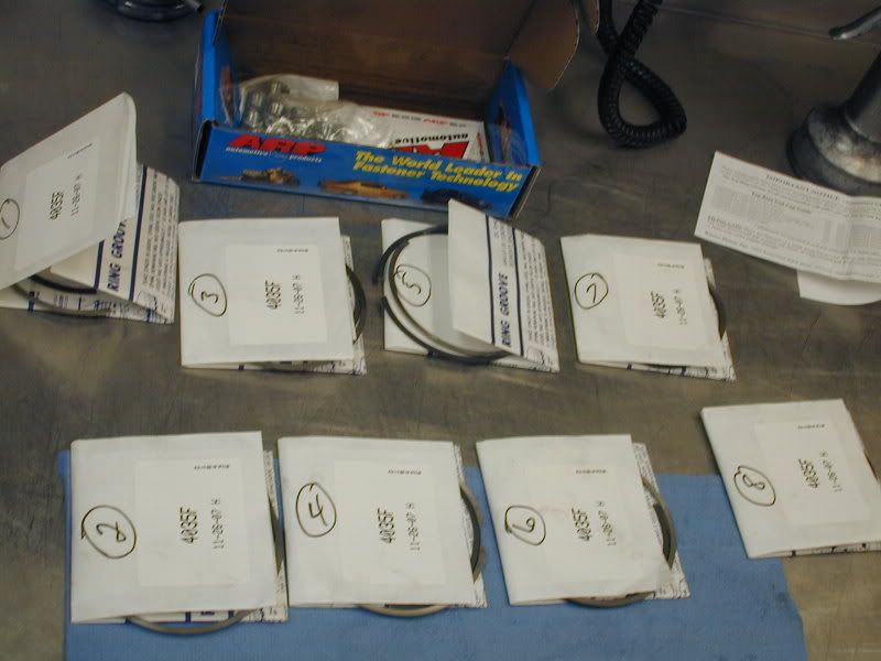
As the rings are completed they are laid out and numbered based on the cylinder they will be installed on.
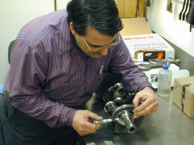
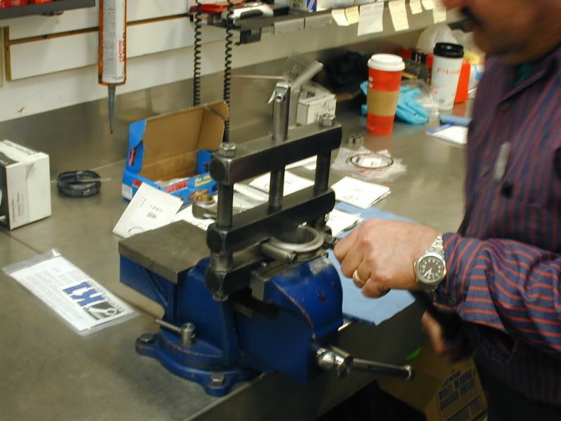
After the rings are filed the connecting rods and the pistons are put together:
First the rods are setup in the connecting rod vise and the bolts are loosened:
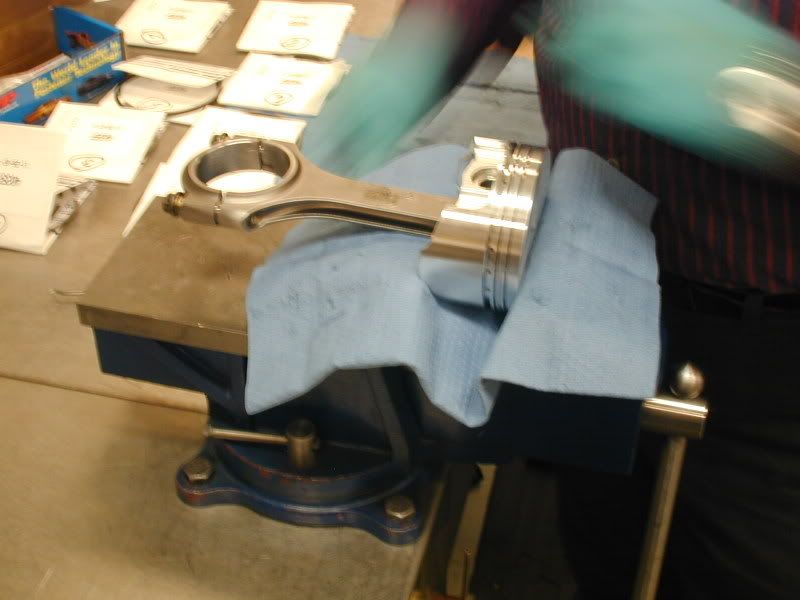
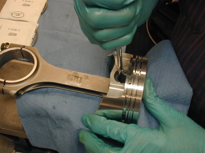
Next the rod is positioned in the piston and the wrist pin is lubricated and slid in to hold them together:
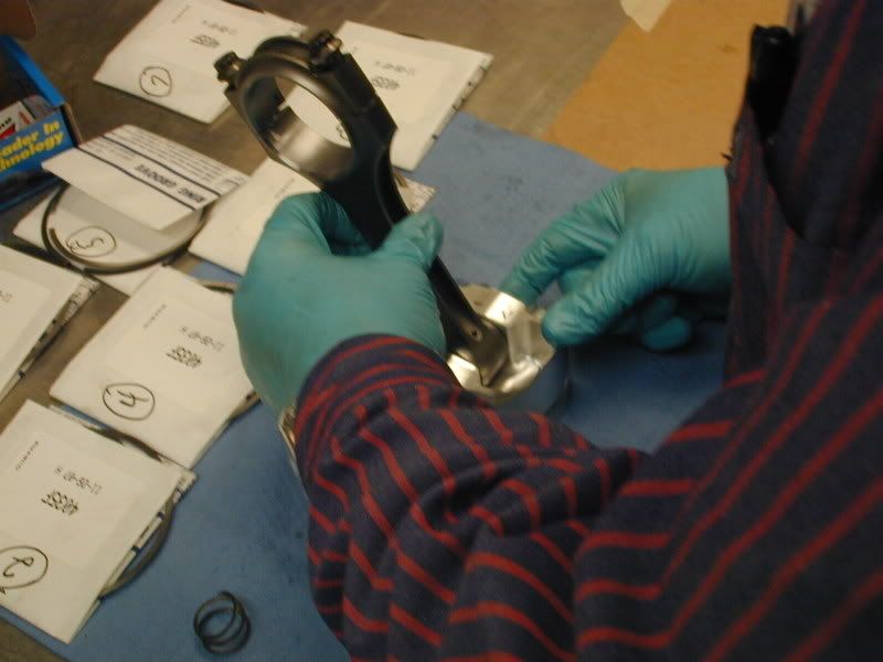
After the pin is installed the spiro locks are installed to secure the wrist pin in the piston/rod assembly:
Once all of the rods and pistons are assembled the piston rings are installed:
After all of the rings are installed on the pistons. The piston/rod assembly is put in the piston box, labeled based on the cylinder the rings were gapped for. The numbering is just an extra step that we take. The cylinders are really all identical due to our machining processes, but it is not a bad habit to have.
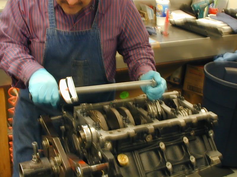
Now that all of our pistons and rods are assembled with rings on the pistons, we now install the assemblies into the bores of the block.
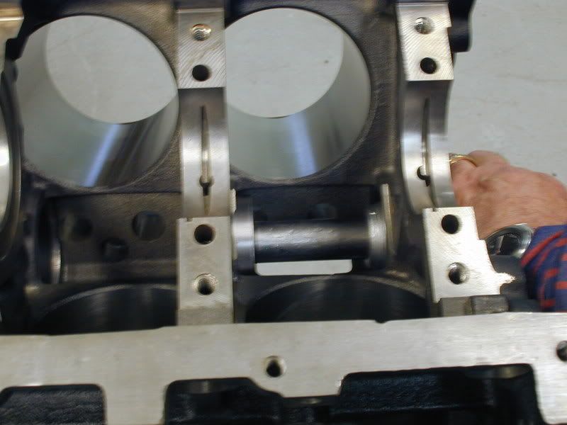
First all of the cylinders are lubricated and the rod is slid into the bore and positioned over the crankshaft:
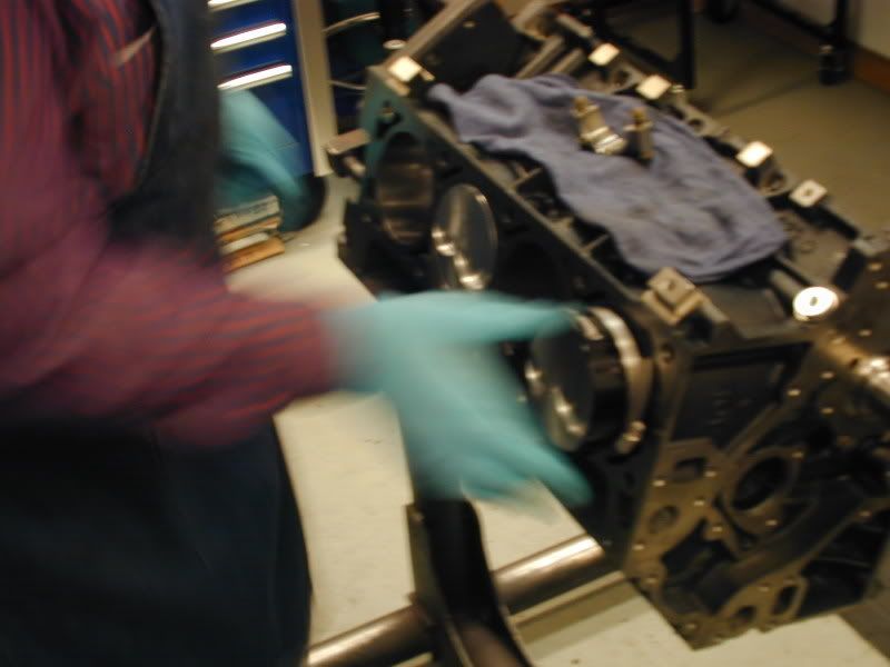
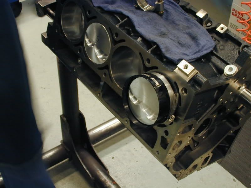
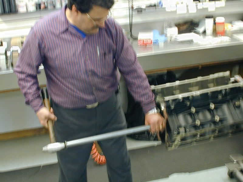
The piston is pushed into the bore by hand, once it is in the bore it is tapped in using a special hammer, the rod is guided down onto the crankshaft journal by hand onto the crankshaft. This ensures no scratching or nicking of the cylinder walls or crankshaft:
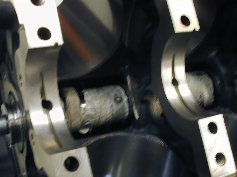
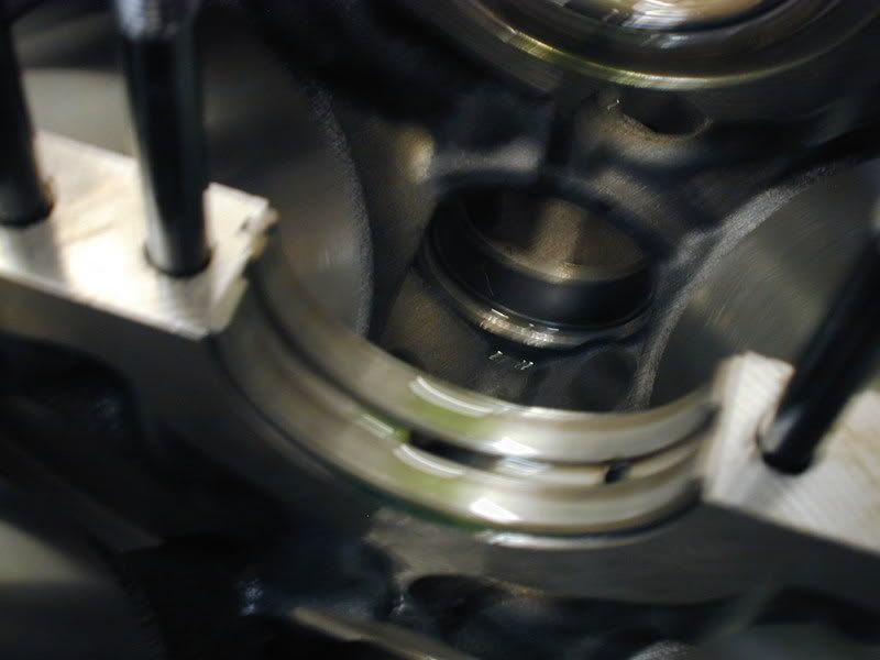
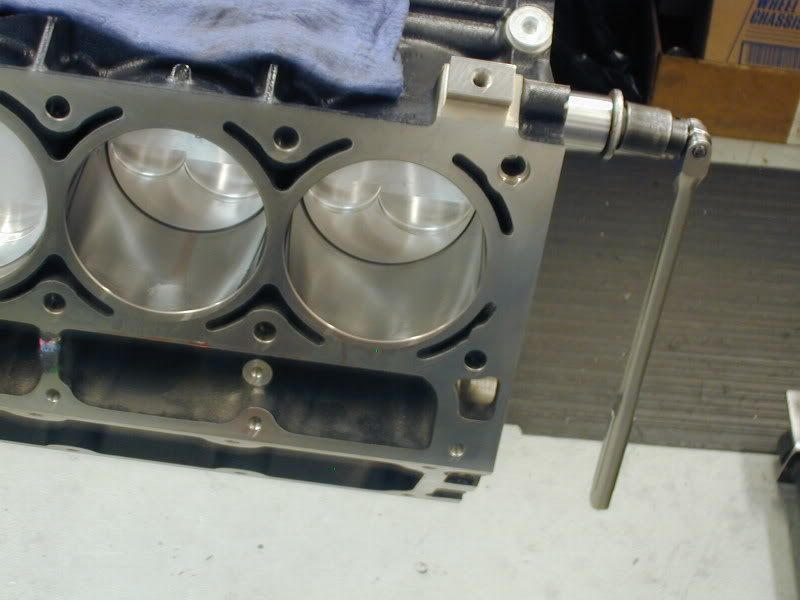
Here is a picture of a rod installed before the rod cap is installed:
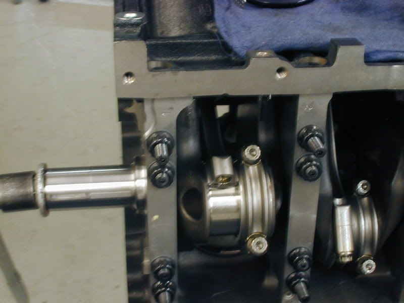
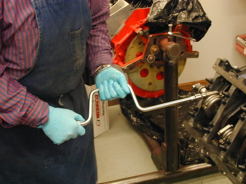
Once all of the pistons and rods are installed in the engine the rod caps are tightened and torqued to specification:
The motor is than rotated to ensure a smoother rotation and no binding:
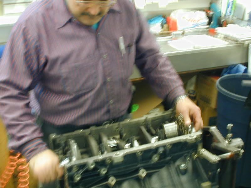
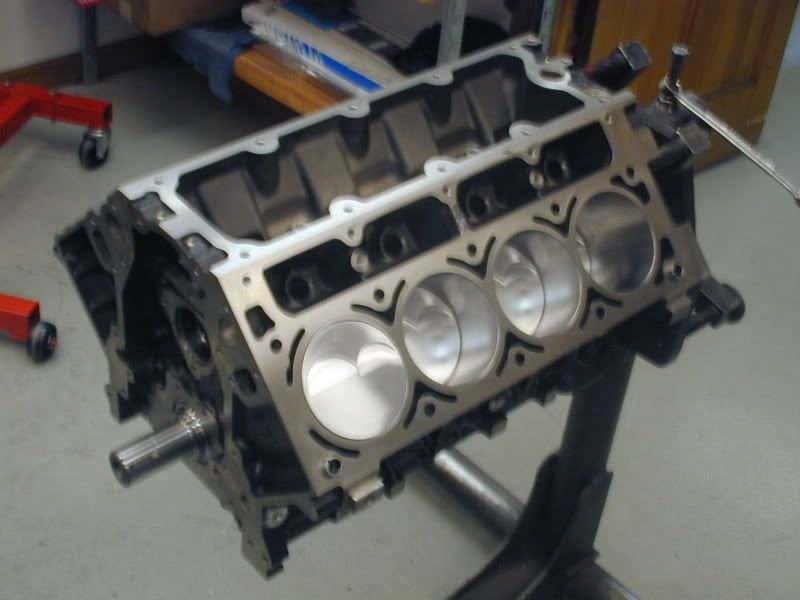
Now we have a completed short block:
This process is repeated until the desired ring gap is achieved.
As the rings are completed they are laid out and numbered based on the cylinder they will be installed on.
After the rings are filed the connecting rods and the pistons are put together:
First the rods are setup in the connecting rod vise and the bolts are loosened:
Next the rod is positioned in the piston and the wrist pin is lubricated and slid in to hold them together:
After the pin is installed the spiro locks are installed to secure the wrist pin in the piston/rod assembly:
Once all of the rods and pistons are assembled the piston rings are installed:
After all of the rings are installed on the pistons. The piston/rod assembly is put in the piston box, labeled based on the cylinder the rings were gapped for. The numbering is just an extra step that we take. The cylinders are really all identical due to our machining processes, but it is not a bad habit to have.
Now that all of our pistons and rods are assembled with rings on the pistons, we now install the assemblies into the bores of the block.
First all of the cylinders are lubricated and the rod is slid into the bore and positioned over the crankshaft:
The piston is pushed into the bore by hand, once it is in the bore it is tapped in using a special hammer, the rod is guided down onto the crankshaft journal by hand onto the crankshaft. This ensures no scratching or nicking of the cylinder walls or crankshaft:
Here is a picture of a rod installed before the rod cap is installed:
Once all of the pistons and rods are installed in the engine the rod caps are tightened and torqued to specification:
The motor is than rotated to ensure a smoother rotation and no binding:
Now we have a completed short block:
Thread Starter
Banned
iTrader: (4)
Joined: Jan 2007
Posts: 539
Likes: 0
From: North Ridgeville, Ohio
Now that the short block is assembled it is time to install the camshaft.
Thanks to Mike and Ron @ Vengeance for the recommendation on the cam. We like to work with the Vengeance guys especially when using Trickflow heads as they have a lot of real world experience with these setups in the cars and on the dyno.
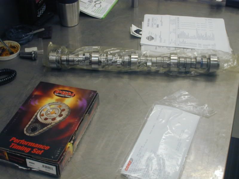
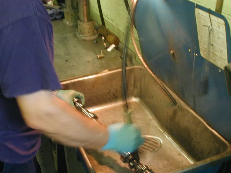
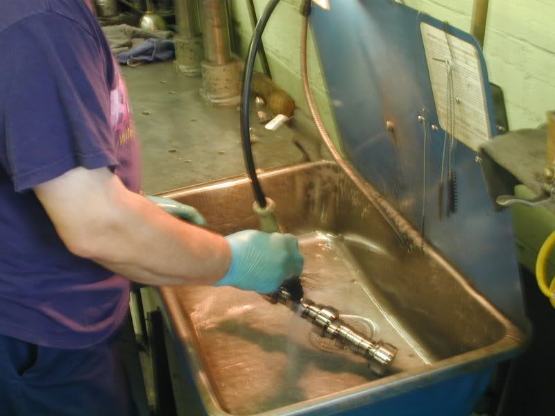
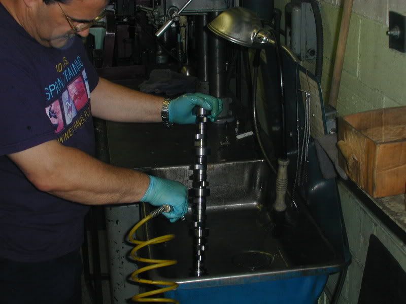
The cam is removed from the packaging and thoroughly cleaned and sprayed off with an air hose in our parts washer:
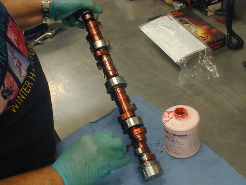
The cam is brought back into the clean assembly room and assembly lube is applied to all of the cam lobes:
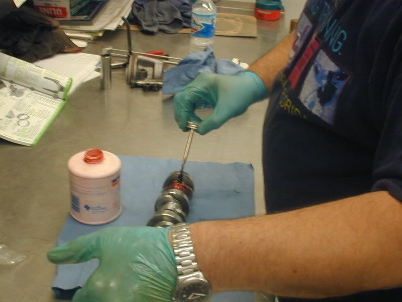
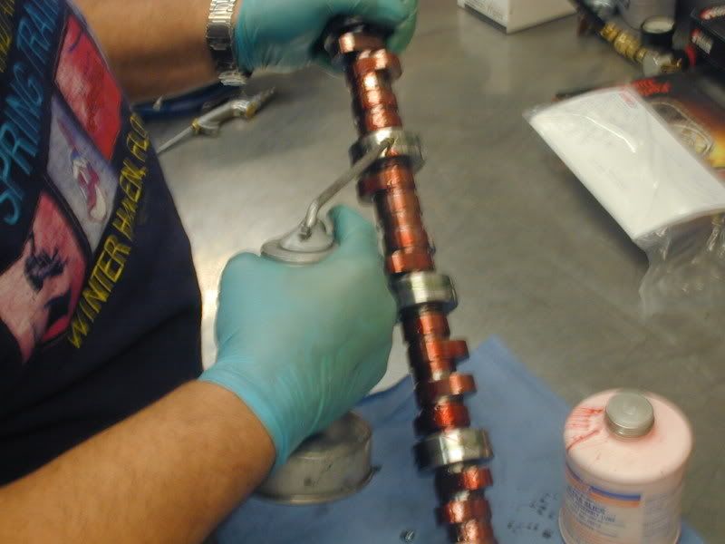
Next oil is applied to the cam journals:
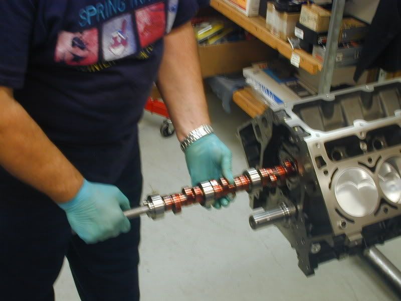
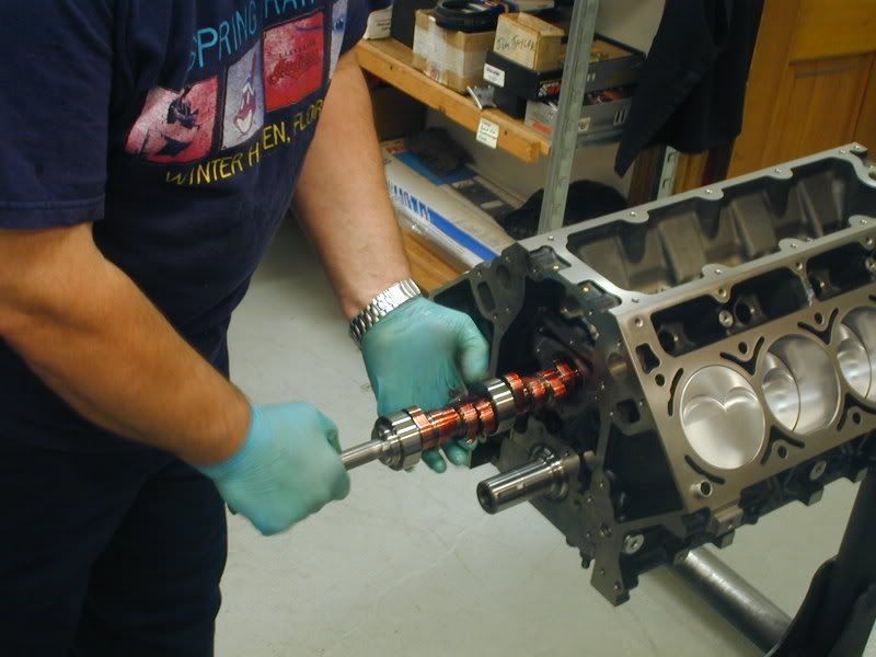
Than the cam is installed:
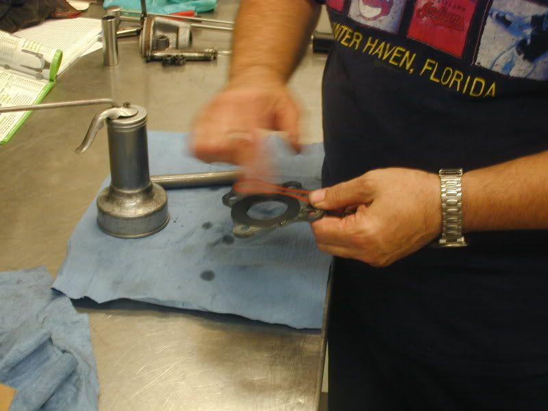
After the cam is in the block, the cam retainer plate is wiped down with a light film of oil and installed.
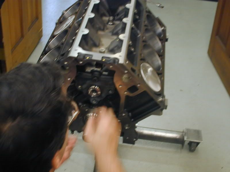
Once the cam is installed it is spun to ensure there is no binding issues with the camshaft. The timing chain is than installed and the cam is degreed in:
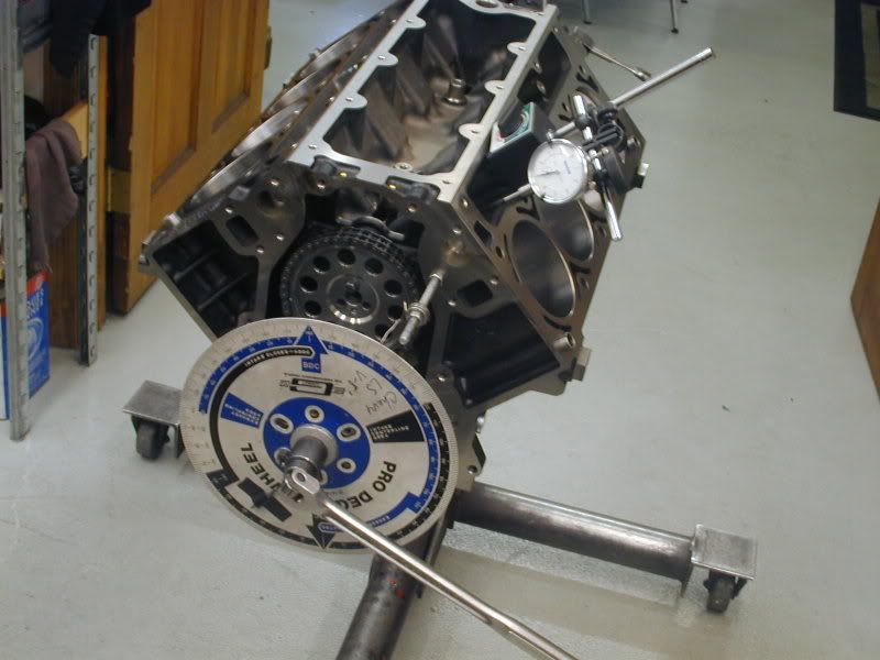
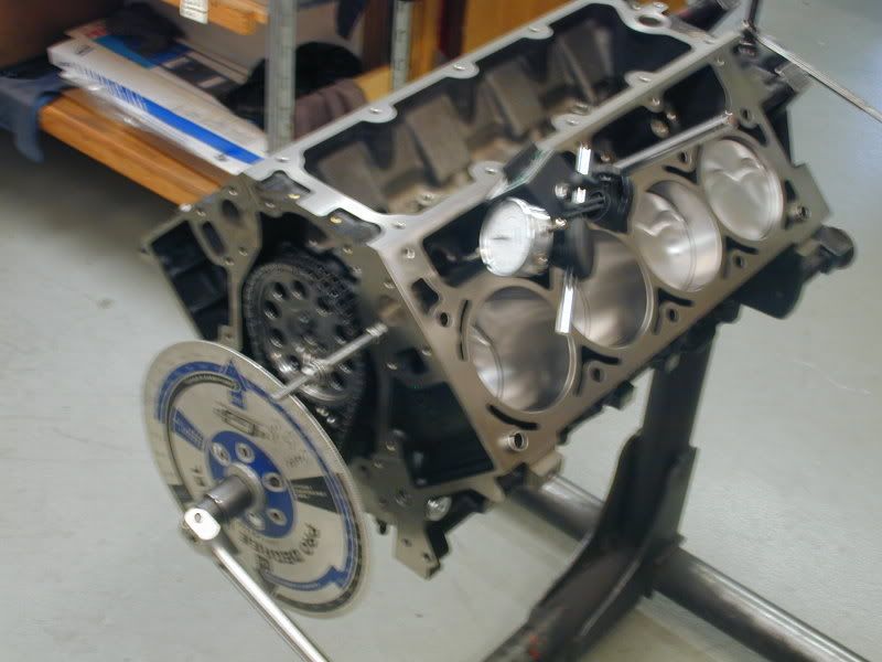
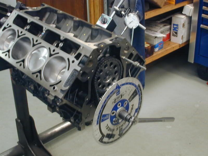
Now the cam is installed and degreed in. We are waiting for the heads and intake to come back from porting and we can finish assembly. STAY TUNED!
Thanks to Mike and Ron @ Vengeance for the recommendation on the cam. We like to work with the Vengeance guys especially when using Trickflow heads as they have a lot of real world experience with these setups in the cars and on the dyno.
The cam is removed from the packaging and thoroughly cleaned and sprayed off with an air hose in our parts washer:
The cam is brought back into the clean assembly room and assembly lube is applied to all of the cam lobes:
Next oil is applied to the cam journals:
Than the cam is installed:
After the cam is in the block, the cam retainer plate is wiped down with a light film of oil and installed.
Once the cam is installed it is spun to ensure there is no binding issues with the camshaft. The timing chain is than installed and the cam is degreed in:
Now the cam is installed and degreed in. We are waiting for the heads and intake to come back from porting and we can finish assembly. STAY TUNED!