When you click on links to various merchants on this site and make a purchase, this can result in this site earning a commission. Affiliate programs and affiliations include, but are not limited to, the eBay Partner Network.
I have a 04 Jeep tj swapped in a 5.3L/4l60e from a 04 silverado, and trying to figure out the correct way to wire up the TCC. I have wired the tcc wire to a relay in a way that I get 12v on key on, and 0v when brake pedal is pressed, and I was told that is wrong, and that I should just run the tcc wire directly to the stop brake light so that the tcc wire receives 12v when brake it pressed instead.
Yes, you want 0v when brake pedal is pressed. Your way will work, though it is a little more complicated than it needs to be.
Originally Posted by bbond105
Why the relay? Just apply 12V to the normally closed side of brake light switch and the other wire to the TCC Brake Switch Signal pin on the PCM.
Getting alot mix responses here. Normal closed, or normal open, which one is it? I did wire it thinking that all gen 3 LS had it that way, closed circuit 12v going through until brake is applied.
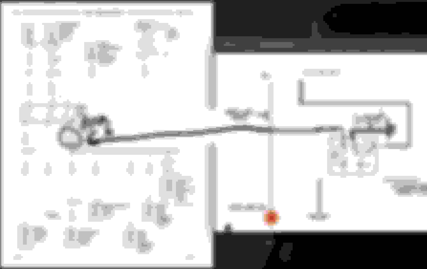
Came across this circuit below, which is the opposite of what image above.
How to know for sure which way is correct?
Cant speak for the 2004 but on my 95 ss with 4l60e if the fuse for brake blows. you lose lockup. So at least in in e 95 pcm 12v is sent to the PCM from the normally closed side of the brake switch
__________________ Frank formerly of Performabuilt, Now just me, What can I build for you today? Call or message me. Click sig pic for my facebook
In most GM brake switches that I have seen there are at least 2 switches built into the 1 switch. 1 is normally open, this is used for brake lights and the other is normally closed which is used for TCC and cruise control.
I believe that I said your way would work but it was a little complicated. Wire it however you like, if it works great why change it.
Thats the thing, you cant just wire it however you like. Some have the switch normally open, some have the switch normally close. Trying to find an answer on how it is wired on an 04 Silverado 1500 4x4. is the switch normally closed (12v key on, 0v when brake is pressed)? or is the switch normally open (0v, 12v when brake is pressed)?
Man, I'm just trying to help. Your question has been answered by me and Frank with both of us giving the same answer. I have been an auto technician since 1982, and I am sure Frank has been doing his thing for a good while too. I don't know how else to help you.
It is very simple.
The Two previous Posters have already stated this Correctly.
The TCC Positive Circuit receives 12 Volts+ when the Ignition is turned on, and when the Engine is running.
The ONLY time that the TCC Positive Circuit does NOT receive 12 Volts+ is when the Brake Pedal is Pressed.
There is ONLY one way in which this can happen.
The Brake Pedal Switch that is used for the TCC Positive Circuit is a "Normally Closed" Design Switch.
Pressing the Brake Pedal OPENS the Switch.
When the Switch is OPEN, Electricity can NOT pass through said Switch.
On the other hand...
The Brake Pedal Switch that is used for the Stop Lamp Positive Circuit is a "Normally Open" Design Switch.
This however has nothing to do with the TCC Positive Circuit.


 Yesterday, 05:48 PM