
Want a good wideband? (Group Purchase)

 11-03-2007 | 05:13 PM
#742
I have a question.
From the website, it looks like the diameter of the gauge is 2 1/16 on the small radius, but what is the overall diameter of the gauge.
Look at the picture below, the reason I need to know is I plan to put the gauge in the center vent of a firebird.
From the website, it looks like the diameter of the gauge is 2 1/16 on the small radius, but what is the overall diameter of the gauge.
Look at the picture below, the reason I need to know is I plan to put the gauge in the center vent of a firebird.
 11-04-2007 | 12:03 AM
#744
Thread Starter
FormerVendor
iTrader: (73)
Joined: Nov 2005
Posts: 4,072
Likes: 0
From: Baton Rouge, LA
I have a question.
From the website, it looks like the diameter of the gauge is 2 1/16 on the small radius, but what is the overall diameter of the gauge.
Look at the picture below, the reason I need to know is I plan to put the gauge in the center vent of a firebird.
From the website, it looks like the diameter of the gauge is 2 1/16 on the small radius, but what is the overall diameter of the gauge.
Look at the picture below, the reason I need to know is I plan to put the gauge in the center vent of a firebird.
This can be mounted in any hole 2-1/16" Most pillars use that diameter
11-04-2007 | 07:57 AM
#745
Thanks. I understand that they will mount in all gauge pillars, but I want to put it in the hvac vents above the radio, and they are larger than 2 1/16", closer to 2 1/2" if not a little larger in diameter.
11-04-2007 | 12:37 PM
#747
Thread Starter
FormerVendor
iTrader: (73)
Joined: Nov 2005
Posts: 4,072
Likes: 0
From: Baton Rouge, LA
__________________________________________________ ___________________________________________
SAW THIS ON ANOTHER FOURM, GREAT HOW TO GUIDE on hooking up wideband to HPT!
MEMBER: 2000C-5
I have gotten a few people email me about wiring a wideband up for logging using the AC pressure sensor. If I do an elaborate How-To on this can it be made into a sticky? I have to go through all the steps time and time again for people on this. I think a lot of people get into HPtuners without purchasing the EIO cable and dont want to pay for the upgrade after they buy a wideband. I was just wondering if I could get a sticky made out of this. I need someone to host it as well.
So here it goes... With Pics!
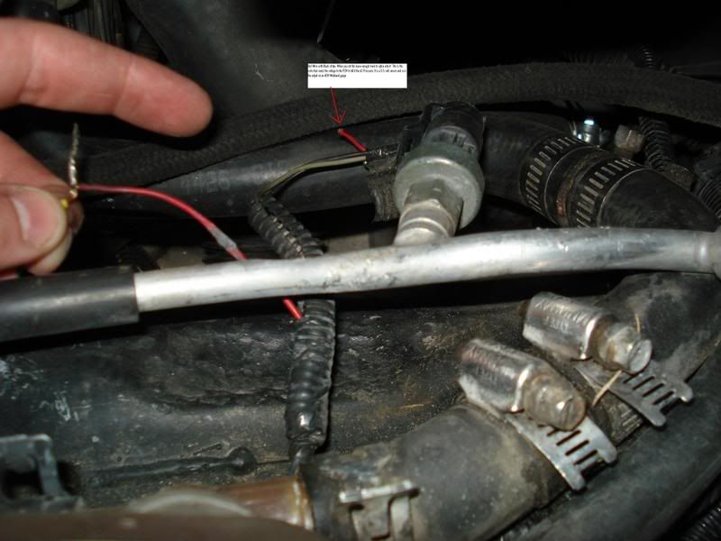
1. First thing to do is track down the AC Pressure sensor. It is located on the passenger side right up in front of the coolant reservoir. Here is a picture of what you are looking for.
2. Now you have three choices on how to do this next step.
1.* The easiest way to do this is to install a switch in this wire you just cut. This way you can switch the output on the wire from the wideband to the AC when you arent tuning. It will take a 3pole switch that has 2 inputs and one output.
2.* If you dont want to run AC just wire the wideband in and leave the sensor unplugged. This one is not for me, AC is a must!
3.* Install quick connect ends where you can unplug the wideband and plug the AC Sensor back up.
3. Of course you will have to wire the Wideband as well. Once everything is wired up check to make sure the wideband is working properly on the gauge display. Once operation is correct we can go on to getting this thing to read into HPtuners.
4. This is very simple to do it sounds harder than it really is. Here it is step by step.
1.- Open VCM Scanner
2.- Open the Table Display
3.- Right click the table
4.- Left click insert
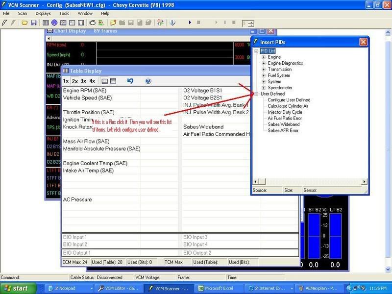
5.- Down at the bottom you will see User Defined if there is a + sign next to it click the + sign and you will see configure user defined.
6.- Double Left click configure user defined
Here is a pic
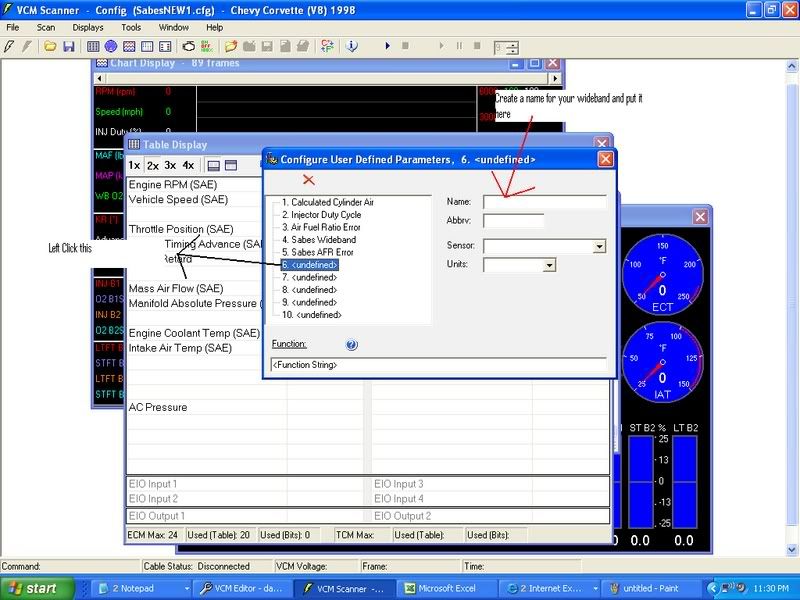
7.- Now click one of the undefined labels and insert a name for your wideband.
8.- Now we need to input the function string that will take the voltage coming from the wideband output and convert it to AFR. At the bottom of this screen you will see a function line. Enter ([PID. 7101]/.5)+10, you will notice mine is 9.8... we will get to this in a minute for now just put 10.
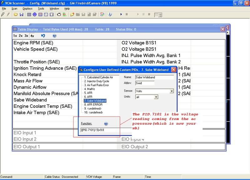
9.- Now the reason my formula is 9.8 is because of voltage drop. When doing some researching I figured out that my wideband was reading .2 different on my HPtuners than the gauge display was showing. So using the formula I basically calibrated my laptop to read the same as my gauge. So you need to scan the car and see if there is any difference, if there is adjust it the way I did.
10. Now lets open the scanner, connect to the car and scan to ensure the PID is working. If you have a switch installed make sure you have it on the wideband. If everything is working good lets move on to creating a histogram.
Creating the Histogram for the wideband
1.- Now that we have created the function already this part is very simple. Open the Scanner, open the histogram display.
2.- To the right of the number 8 you will see a configure button. Click that.
3.- The easiest way to do this is to use the wideband configuration thats default on the scanner. Click the wideband input, I am wanting to think its the #6. I will post pics of this setup tonight.
4.- You will then see how the wideband is default setup. If you look where it says sensor you will see that next to the sensor it says air fuel ratio. To the right of that you will see PID:, Click next to where it says PID:.
5.- You should see the custom PID we made earlier for the wideband. It will be listed under the user configured and will be named the name you created earlier. Now double click the custom pid you created and hit the floppy disk in the top left corner to commit the changes.
6.- Do another scan and ensure everything is working properly.
__________________________________________________ _____________________________________
Reading a Wideband through the EGR or A/C Pressure Switch
EGR
• The EGR wire is located at Pin 55 on the Blue Connector of the PCM.
• On vehicles that come with an EGR, there will be a Brown wire at Pin 55, it is designated “EGR Pintle Position Sensor Signal” in a pinout schematic.
• If your vehicle did not come equipped with an EGR (Corvette), just add a wire to the PCM at Pin 55, everything still works the same. I went to a junkyard and found a plug under the hood of a GM vehicle with the same type of ends as the PCM wires. Click here for instructions on how to gain access to your PCM.
• Connect the Wideband 02 wire with the 0-5v output to the EGR wire at Pin 55. This may be all you need to do with some widebands, some others require a ground. Check the wiring schematic for your specific unit.
A/C Pressure Switch
• There are 3 wires connected to the A/C Pressure sensor. The Red wire with Black stripe that is going to the PCM is the one we want to use. You can go to a junkyard and find another connector to plug into this so you can switch back and forth or you can buy a Maintain switch that, when you switch it one way it reads from the A/C sensor and when switched the other way, it reads from the Wideband O2 output wire. Either way will work fine, so that you can easily put it back to normal when done tuning.
HP Tuner Scanner
• Now that the wiring is done, you need to set it up in HP Tuners. You will need some information on your specific wideband that will be in the widebands paperwork. You will have to set up a formula to change the voltage (0-5v) into your AFR wideband reading. It will look like this:
VOLTS / (VOLTAGE RANGE/DEVICE RANGE) + (MINIMUM VALUE OF DEVICE READING) = AFR
VOLTS = the voltage that the wideband 02 sensor is putting out to the EGR wire
VOLTAGE RANGE = typically 5v (0-5v), some people use the narrowband 02 input (not recommended) which is 1v (0-1v)
DEVICE RANGE = the range your wideband is set to read. If the wideband is set to read from 10 – 20 AFR, then the range will be 10. If set to read from 8 – 22 AFR, the range will be 14, etc.
MINIMUM VALUE OF DEVICE READING = the lowest number that your wideband is set to read. In the above examples, it would be 10 for the first example, and 8 for the second.
I am using a PLX SM-AFR 250, so I will use it for my example. The formula will be:
VOLTS / (5/10) + 10 = AFR or,
(VOLTS / .5) + 10 = AFR
• Since HP Tuners Scanner will be using the EGR or AC Pressure switch to get its readings from, we need to add that into the formula. The PID for the EGR on LS1 based cars is PID.2811 (EGR Position). Now the formula reads like this:
([PID.2811]/.5)+10 = AFR
• The formula for the A/C Pressure switch is the same, you will just have to change the PID to PID.7101.
([PID.7101]/.5)+10 = AFR
Custom PID
• Open Table Display in Scanner
• Right click any blank line and choose Insert
• This will open the Insert PIDs display
• Here you will see PID List, AUX Input List and User Defined. Click the + next to User Defined to open the drop down list
• Double click Configure User Defined to open Configure User Defined Parameters
• Click on one of the numbers with <undefined> next to it
• For Name:, put the name of your choice, say, Air Fuel Ratio
• For Abbrv:, put AFR
• For Sensor:, open the drop down box and choose Air Fuel Ratio
• For Units:, open the drop down box and choose :1
• Under Function:, insert your formula. For the SM-AFR it is ([PID.2811]/.5)+10
• If you are using the A/C Pressure switch, use the formula: ([PID.7101]/.5)+10
• That’s it, just click the X at the top right to close the box and click the Save icon on the Histogram Configuration page.
• To make a custom PID for AFR % Error make your way back to the Configure User Defined Parameters page. There will already be an Air Fuel Ratio Error PID. Open it and look at the information in the Function box.
• Copy this formula EXACTLY. It will look like this:
100*([SENS.120]-[SENS.121])/[SENS.121]
• Since SENS.120 is the AFR SENSOR we want to create a new Custom PID and substitute our new formula in place of SENS.120, then enter this into the Function box. Now it will look like this:
100*((([PID.2811]/.5)+10)-[SENS.121])/[SENS.121] or
100*((([PID.7101]/.5)+10)-[SENS.121])/[SENS.121] for the A/C Pressure switch.
• On this Custom PID, give it a name, use AFR%Error for the Abbrv, leave Sensor blank, and use % for Units.
• Now, you can change the information in your VE and MAF Histograms to use the custom PIDs that you just made.
• Don’t forget that you will have to log EGR Position (PID List/Engine/Emissions/EGR Position (V)) for reading throught the EGR or A/C Pressure (PID List/System/AC/AC Pressure (V)), AFR, AFR % Error and AFR Commanded in the Table display. Also, in Editor, you have to enable EGR if it has been disabled or your car didn’t come with it.
SAW THIS ON ANOTHER FOURM, GREAT HOW TO GUIDE on hooking up wideband to HPT!
MEMBER: 2000C-5
I have gotten a few people email me about wiring a wideband up for logging using the AC pressure sensor. If I do an elaborate How-To on this can it be made into a sticky? I have to go through all the steps time and time again for people on this. I think a lot of people get into HPtuners without purchasing the EIO cable and dont want to pay for the upgrade after they buy a wideband. I was just wondering if I could get a sticky made out of this. I need someone to host it as well.
So here it goes... With Pics!
1. First thing to do is track down the AC Pressure sensor. It is located on the passenger side right up in front of the coolant reservoir. Here is a picture of what you are looking for.
2. Now you have three choices on how to do this next step.
1.* The easiest way to do this is to install a switch in this wire you just cut. This way you can switch the output on the wire from the wideband to the AC when you arent tuning. It will take a 3pole switch that has 2 inputs and one output.
2.* If you dont want to run AC just wire the wideband in and leave the sensor unplugged. This one is not for me, AC is a must!
3.* Install quick connect ends where you can unplug the wideband and plug the AC Sensor back up.
3. Of course you will have to wire the Wideband as well. Once everything is wired up check to make sure the wideband is working properly on the gauge display. Once operation is correct we can go on to getting this thing to read into HPtuners.
4. This is very simple to do it sounds harder than it really is. Here it is step by step.
1.- Open VCM Scanner
2.- Open the Table Display
3.- Right click the table
4.- Left click insert
5.- Down at the bottom you will see User Defined if there is a + sign next to it click the + sign and you will see configure user defined.
6.- Double Left click configure user defined
Here is a pic
7.- Now click one of the undefined labels and insert a name for your wideband.
8.- Now we need to input the function string that will take the voltage coming from the wideband output and convert it to AFR. At the bottom of this screen you will see a function line. Enter ([PID. 7101]/.5)+10, you will notice mine is 9.8... we will get to this in a minute for now just put 10.
9.- Now the reason my formula is 9.8 is because of voltage drop. When doing some researching I figured out that my wideband was reading .2 different on my HPtuners than the gauge display was showing. So using the formula I basically calibrated my laptop to read the same as my gauge. So you need to scan the car and see if there is any difference, if there is adjust it the way I did.
10. Now lets open the scanner, connect to the car and scan to ensure the PID is working. If you have a switch installed make sure you have it on the wideband. If everything is working good lets move on to creating a histogram.
Creating the Histogram for the wideband
1.- Now that we have created the function already this part is very simple. Open the Scanner, open the histogram display.
2.- To the right of the number 8 you will see a configure button. Click that.
3.- The easiest way to do this is to use the wideband configuration thats default on the scanner. Click the wideband input, I am wanting to think its the #6. I will post pics of this setup tonight.
4.- You will then see how the wideband is default setup. If you look where it says sensor you will see that next to the sensor it says air fuel ratio. To the right of that you will see PID:, Click next to where it says PID:.
5.- You should see the custom PID we made earlier for the wideband. It will be listed under the user configured and will be named the name you created earlier. Now double click the custom pid you created and hit the floppy disk in the top left corner to commit the changes.
6.- Do another scan and ensure everything is working properly.
__________________________________________________ _____________________________________
Reading a Wideband through the EGR or A/C Pressure Switch
EGR
• The EGR wire is located at Pin 55 on the Blue Connector of the PCM.
• On vehicles that come with an EGR, there will be a Brown wire at Pin 55, it is designated “EGR Pintle Position Sensor Signal” in a pinout schematic.
• If your vehicle did not come equipped with an EGR (Corvette), just add a wire to the PCM at Pin 55, everything still works the same. I went to a junkyard and found a plug under the hood of a GM vehicle with the same type of ends as the PCM wires. Click here for instructions on how to gain access to your PCM.
• Connect the Wideband 02 wire with the 0-5v output to the EGR wire at Pin 55. This may be all you need to do with some widebands, some others require a ground. Check the wiring schematic for your specific unit.
A/C Pressure Switch
• There are 3 wires connected to the A/C Pressure sensor. The Red wire with Black stripe that is going to the PCM is the one we want to use. You can go to a junkyard and find another connector to plug into this so you can switch back and forth or you can buy a Maintain switch that, when you switch it one way it reads from the A/C sensor and when switched the other way, it reads from the Wideband O2 output wire. Either way will work fine, so that you can easily put it back to normal when done tuning.
HP Tuner Scanner
• Now that the wiring is done, you need to set it up in HP Tuners. You will need some information on your specific wideband that will be in the widebands paperwork. You will have to set up a formula to change the voltage (0-5v) into your AFR wideband reading. It will look like this:
VOLTS / (VOLTAGE RANGE/DEVICE RANGE) + (MINIMUM VALUE OF DEVICE READING) = AFR
VOLTS = the voltage that the wideband 02 sensor is putting out to the EGR wire
VOLTAGE RANGE = typically 5v (0-5v), some people use the narrowband 02 input (not recommended) which is 1v (0-1v)
DEVICE RANGE = the range your wideband is set to read. If the wideband is set to read from 10 – 20 AFR, then the range will be 10. If set to read from 8 – 22 AFR, the range will be 14, etc.
MINIMUM VALUE OF DEVICE READING = the lowest number that your wideband is set to read. In the above examples, it would be 10 for the first example, and 8 for the second.
I am using a PLX SM-AFR 250, so I will use it for my example. The formula will be:
VOLTS / (5/10) + 10 = AFR or,
(VOLTS / .5) + 10 = AFR
• Since HP Tuners Scanner will be using the EGR or AC Pressure switch to get its readings from, we need to add that into the formula. The PID for the EGR on LS1 based cars is PID.2811 (EGR Position). Now the formula reads like this:
([PID.2811]/.5)+10 = AFR
• The formula for the A/C Pressure switch is the same, you will just have to change the PID to PID.7101.
([PID.7101]/.5)+10 = AFR
Custom PID
• Open Table Display in Scanner
• Right click any blank line and choose Insert
• This will open the Insert PIDs display
• Here you will see PID List, AUX Input List and User Defined. Click the + next to User Defined to open the drop down list
• Double click Configure User Defined to open Configure User Defined Parameters
• Click on one of the numbers with <undefined> next to it
• For Name:, put the name of your choice, say, Air Fuel Ratio
• For Abbrv:, put AFR
• For Sensor:, open the drop down box and choose Air Fuel Ratio
• For Units:, open the drop down box and choose :1
• Under Function:, insert your formula. For the SM-AFR it is ([PID.2811]/.5)+10
• If you are using the A/C Pressure switch, use the formula: ([PID.7101]/.5)+10
• That’s it, just click the X at the top right to close the box and click the Save icon on the Histogram Configuration page.
• To make a custom PID for AFR % Error make your way back to the Configure User Defined Parameters page. There will already be an Air Fuel Ratio Error PID. Open it and look at the information in the Function box.
• Copy this formula EXACTLY. It will look like this:
100*([SENS.120]-[SENS.121])/[SENS.121]
• Since SENS.120 is the AFR SENSOR we want to create a new Custom PID and substitute our new formula in place of SENS.120, then enter this into the Function box. Now it will look like this:
100*((([PID.2811]/.5)+10)-[SENS.121])/[SENS.121] or
100*((([PID.7101]/.5)+10)-[SENS.121])/[SENS.121] for the A/C Pressure switch.
• On this Custom PID, give it a name, use AFR%Error for the Abbrv, leave Sensor blank, and use % for Units.
• Now, you can change the information in your VE and MAF Histograms to use the custom PIDs that you just made.
• Don’t forget that you will have to log EGR Position (PID List/Engine/Emissions/EGR Position (V)) for reading throught the EGR or A/C Pressure (PID List/System/AC/AC Pressure (V)), AFR, AFR % Error and AFR Commanded in the Table display. Also, in Editor, you have to enable EGR if it has been disabled or your car didn’t come with it.
Last edited by Derek @ EDO; 11-04-2007 at 12:45 PM.
11-06-2007 | 12:29 AM
#750
I don't know if this has been asked yet and I really don't want to read through 38 pages of this. But I want to know if this will work good with nitrous? All I have now is a bolt-on, cam only LT1 (mods in sig). But I plan on getting nitrous by next year.
11-06-2007 | 04:26 PM
#751
Thread Starter
FormerVendor
iTrader: (73)
Joined: Nov 2005
Posts: 4,072
Likes: 0
From: Baton Rouge, LA
I don't have a set time line, As long as you guys have interest in them i will sale them for this price. When i get low on the in-stock units i will inform you guys. We still have these in stock ready to ship.
This will be perfect for nitrous and i will give you an example of why:
Suppose you have a wet kit installed on your car and the fuel solenoid is stuck "closed"
If you spray and have a wideband you would instantly see a LEAN condition, you can disarm your nitrous and then troubleshoot your setup.
Just in general its nice to have. It really is a piece of mind knowing your vehicle is getting the appropriate amount of fuel and air at all times.
11-08-2007 | 08:44 PM
#752
Thread Starter
FormerVendor
iTrader: (73)
Joined: Nov 2005
Posts: 4,072
Likes: 0
From: Baton Rouge, LA
Come on guys, get yourself an early Christmas present! 
We are ready to ship these things out!
Thanks,
Derek
P.S. For all you guys that have recently placed your order how do you like your setup?
We are ready to ship these things out!
Thanks,
Derek
P.S. For all you guys that have recently placed your order how do you like your setup?
11-12-2007 | 10:30 PM
#753

Just wanted to say thanks for the great product.
I'm using em as fulltime on both my trucks.
Two units and both work great!!!! Also very quick with the shipping on em.
Thanks again!!!!!!!!!!!!!!!!!!!!
I'm using em as fulltime on both my trucks.
Two units and both work great!!!! Also very quick with the shipping on em.
Thanks again!!!!!!!!!!!!!!!!!!!!
11-13-2007 | 08:29 PM
#755
Do I need anything else to get this working in my car if I buy one? Will it read correctly if I just wire up what it comes with and go? I saw the pics and the module has lots of plug in spots so it kinda has me worried.
Once again don't want to go through 38 pages.
Once again don't want to go through 38 pages.
11-13-2007 | 08:50 PM
#756
Thread Starter
FormerVendor
iTrader: (73)
Joined: Nov 2005
Posts: 4,072
Likes: 0
From: Baton Rouge, LA
http://www.plxdevices.com/Installati...UsersGuide.pdf
Its a COMPLETE wideband setup!
Thanks,
Derek


