
Viper 5204V Install - 02 WS6 M6 (Almost done need a little more help)
 12-08-2014, 08:44 PM
#1
On The Tree
Thread Starter
iTrader: (2)

Join Date: Sep 2010
Location: Madison, AL
Posts: 136
Likes: 0
Received 0 Likes
on
0 Posts
I'm getting ready to install a Viper 5204V Remote Start/Alarm on my 02 WS6 M6. I've got a lot of question, so I thought I'd just start a thread. I couldn't find much on this, so I thought this might help out someone in the future.
I'm working mapping the wires out before I tear into the car. I'll use the following post for the wire layout.
First question. I got the xpresskit bypass XK06 module Viper said I needed. After some research I'm wondering if I don't need it. If the VATs Bypass Mod has been done, I don't need the XK06, correct?
I bought my car some time ago with 40k on her. There was a dealer aftermarket alarm on it, that I've since ripped out. In doing so it appeared as if the VATs bypass mod had already been done.
Last edited by CORYSTA; 12-30-2014 at 05:55 PM.
 12-08-2014, 08:45 PM
#2
On The Tree
Thread Starter
iTrader: (2)
Join Date: Sep 2010
Location: Madison, AL
Posts: 136
Likes: 0
Received 0 Likes
on
0 Posts
Based off the Viper module diagram and information I've found online. Please correct any of my errors and feel free/please help me fill it in.
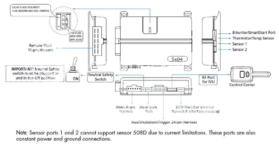
Main Harness (H1), 6-pin connector
H2 Harness, 24-pin connector
Remote Start, (H3) 10-pin connector
Door Lock, 3-pin connector
Reference from/for diagrams: http://www.bfranker.badz28.com/fbody/alarm96up3.htm
Trunk Pop
Will need to do the VATS Bypass as I have, or use a Bypass such as the XK06.

Main Harness (H1), 6-pin connector
- H1/1 RED (+)12VDC CONSTANT INPUT
- Backside of the fuse box open slot (BATT)
- 25AMP Fuse
- Backside of the fuse box open slot (BATT)
- H1/2 BLACK (-) CHASSIS GROUND
- put a ring terminal on and attach to a factory bolt attached to a good amount of metal
- Passenger side next to door
- H1/3 BROWN (+) SIREN OUTPUT
- siren red wire already as stated will attach to the brown off the viper
- black Siren wire will be grounded to another good metal point.
- H1/4 WHITE/BROWN PARKING LIGHT ISOLATION WIRE - PIN 87a of onboard relay
- N/A
- H1/5 WHITE PARKING LIGHT OUTPUT
- Working behind the fuse box
- Brown wire coming off the Headlight switch assembly
- Use blue quick slice connector to switch into this brown
- Light Flash Polarity
- “Connection will be made to a positive 12V wire, so ensure your alarm’s output for this feature is also +12V”
- This is where I set the alarm’s “LIGHT FLASH POLARITY” to positive.
- H1/6 ORANGE (-) 500mA GROUND WHEN ARMED OUTPUT
- Connect to Window Module H2/4 ORANGE
H2 Harness, 24-pin connector
- H2/1 PINK/WHITE (-) 200mA IGNITION/FLEX RELAY CONTROL OUTPUT
- H2/2 BLACK/WHITE (-) NEUTRAL SAFETY INPUT
- Chassis Ground
- H2/3 BLUE/WHITE (-) 200mA 2ND STATUS /REAR DEFOGGER OUTPUT
- Need a relay to operate the defrost/defogger
- 85 = 5902 Blue/White
- 86 = Fused 12V
- 87 = Defogger Gray
- 30 = Fused 12V
- Rear Defrost ....... Gray (+) ......... At Rear Window Defogger Switch
- Need a relay to operate the defrost/defogger
- H2/4 GREEN/BLACK (-) 200mA OEM ALARM DISARM OUTPUT
- H2/5 RED/WHITE (-) 200mA TRUNK RELEASE OUTPUT
- Port 85 Trunk Pop Relay
- H2/6 GREEN (-) DOOR TRIGGER INPUT (N/C* OR N/O)
- USE DIODES Preventing a Current from traveling BACK to the BCM and you can bridge the three
- BCM D11 GRY/BLK Driver Door Open Input
- BCM D12 BLK/WHT Passenger DOI
- Check for – or + output
- H2/7 BLACK/YELLOW (-) 200mA DOME LIGHT SUPERVISION OUTPUT
- What the crap is this? Why would I need a Dome Light OUTPUT from the alarm???
- H2/8 BROWN/BLACK (-) 200mA HORN HONK OUTPUT
- Horn Wire BCM C9 BLACK
- H2/9 DARK BLUE (-) 200mA STATUS OUTPUT
- Clutch Bypass Relay IF NEEDED
- 86 – H2/9 DARK BLUE (-)
- 85 – 12V Constant
- 87 – PPL/WHT off Clutch Start Switch
- 30 – DRK/GRN off Clutch Start Switch
- Could possibly connect to BCM C11 YEL/BLK Starter Relay Control (Domestic), maybe???
- Clutch Bypass Relay IF NEEDED
- H2/10 PINK (-) 200mA IGNITION 1 OUTPUT
- H2/11 WHITE/BLACK (-) 200mA AUX 3 OUTPUT
- H2/12 VIOLET (+) DOOR TRIGGER INPUT
- H2/13 WHITE/VIOLET (-) 200mA AUX 1 OUTPUT
- Window Module 535T-H2/3 RED/WHITE Wire
- H2/14 VIOLET/BLACK (-) 200mA AUX 2 OUTPUT
- H2/15 ORANGE/BLACK (-) 200mA AUX 4 OUTPUT
- H2/16 BROWN (+) BRAKE SHUTDOWN INPUT
- Brake position Switch
- Light Blue Wire
- Test will give +12V when brake is pressed.
- Or Connect to Clutch Anticipation Switch
- Grey (check to make sure wire gives 12V when grounded)
- Brake position Switch
- H2/17 GREY (-) HOOD PIN INPUT (N/C OR N/O)
- Hood Pin Switch connection, if used.
- H2/18 VIOLET/YELLOW (-) 200mA STARTER OUTPUT
- H2/19 BLUE (-) TRUNK PIN/ INSTANT TRIGGER INPUT (N/C OR N/O)
- Trunk Input
- BCM D13 ORN/BLK Rear Compartment Lid Ajar Input
- Trunk Input
- H2/20 GREY/BLACK (-) DIESEL WAIT TO START INPUT
- N/A
- H2/21 WHITE/BLUE (-) REMOTE START/ TURBO TIMER ACTIVATION INPUT
- H2/22 ORANGE (-) 200mA ACCESSORY OUTPUT
- H2/23 VIOLET/WHITE TACHOMETER INPUT
- PCM Red Connector, Pin 10, White wire.
- H2/24 GREEN/WHITE (-) 200mA OEM ALARM ARM OUTPUT
Remote Start, (H3) 10-pin connector
- H3/1 PINK (+) IGNITION 1 INPUT/OUTPUT
- Key Cylinder Option
- connect to the Pink wire coming off the key cylinder
- (thicker gauge shows 12v only when key is at the run position right before crank)
- connect to the Pink wire coming off the key cylinder
- Key Cylinder Option
- H3/2 RED/WHITE (87) FLEX RELAY +12V INPUT (30A FUSED)
- Attach to H3/6
- H3/3 ORANGE (+) ACCESSORY OUTPUT
- ORANGE wire off of ignition switch
- Test: shows 12V when ignition switch is turned to run, 0V at Off and ACC
- ORANGE wire off of ignition switch
- H3/4 VIOLET (+) STARTER OUTPUT (CAR SIDE OF THE STARTER KILL)
- See H3/5
- H3/5 GREEN (+) STARTER INPUT (KEY SIDE OF THE STARTER KILL)
- starter kill relay you take the starter wire on the car Yellow wire and cut the wire in half one end goes to the green wire the other to the black wire. (Green and Black Wire Thicker)
- (thicker gauge coming off key cylinder)
- (there may what looks like a yellow wire but it may not be it may be a yellow shield with multiple wires inside DO NOT TOUCH THIS IS AND AIRBAG WIRE. also yellow plugs are airbag wires too!!!)
- starter kill relay you take the starter wire on the car Yellow wire and cut the wire in half one end goes to the green wire the other to the black wire. (Green and Black Wire Thicker)
- H3/6 RED IGNITION 1 +12V INPUT (30A FUSED)
- red wire coming off the key cylinder
- (thicker wire that always will show 12v)
- red wire coming off the key cylinder
- H3/7 PINK/WHITE (30) FLEX RELAY OUTPUT (car side of ign, acc or starter wire)
- Brown wire off of ignition switch
- H3/8 PINK/BLACK (87a) FLEX RELAY INPUT (key side of ign, acc or starter wire if needed)
- H3/9 RED/BLACK ACCESSORY/STARTER RELAY +12V INPUT (30A FUSED)
- Attach to H3/6
- H3/10 NC No Connection
Door Lock, 3-pin connector
Reference from/for diagrams: http://www.bfranker.badz28.com/fbody/alarm96up3.htm
- Need 2 relays, for our purposes relay x and y
- 85x to 85y to constant +12V source
- Can use same source for trunk pop/red off fuse block
- 87x to 87y to Ground Source
- 86x to BLUE (-) 500mA UNLOCK OUTPUT
- 86y to GREEN (-) 500mA LOCK OUTPUT
- 30x to unlock wire diodes
- 30y to lock wire
- BCM Green Connector RED/BLACK
- 85x to 85y to constant +12V source
- Need 2 1amp or 2 amp diodes
- Anode side of a diode
- Relay will be used to wake up BCM for Door UnLOCK
- BROWN wire at BCM Black Connector (D BRN Accessory Positive (+) V) Relay Time
- 30 – BRN off BCM
- 87 & 86 – 12v Constant
- 85 – H2/22 Orange (-)
- Anode side of a diode
- Orange/Black Unlock wire off the BCM D on 6-pin connector
- will show 12v then when you press and hold unlock it will drop to 0v
- Orange/Black Unlock wire off the BCM D on 6-pin connector
- Anode side of a diode
- BLUE (-) 500mA UNLOCK OUTPUT
- 86x
- EMPTY NOT USED
- GREEN (-) 500mA LOCK OUTPUT
- 86y
Trunk Pop
- Need Standard Automotive Relay
- Red/White Stripe
- Go to port 85 on relay
- H2/5 Red/White (-) 200mA TRUNK RELEASE OUTPUT
- port 86 and 87 on relay
- Attach to a constant 12v source
- (can attach to our red off fuse block)
- Attach to a constant 12v source
- port 30 on Relay 2 OPTIONS
- BCM
- Brown wire in the blue plug on the BCM D4.
- test this wire it will sit at 0v when probed the jump to 12v when you press the trunk release button in the car.
- Hatch release Relay
- Black/White wire
- Splice a wire to it that’ll be ran to the relay
- test this wire it will sit at 0v when probed the jump to 12v when you press the trunk release button in the car.
- BCM
Will need to do the VATS Bypass as I have, or use a Bypass such as the XK06.
Last edited by CORYSTA; 01-10-2015 at 10:48 AM.
12-09-2014, 01:01 PM
#3
On The Tree
Thread Starter
iTrader: (2)
Join Date: Sep 2010
Location: Madison, AL
Posts: 136
Likes: 0
Received 0 Likes
on
0 Posts
- 535T-H1/1 VIOLET Driver-Side Ground Path Input for down(-)
- wire provides the ground path for the driver-side motor down side.
- Connect this wire to a paint-free surface on the vehicle chassis. Use a factory bolt if possible.
- 535T-H1/2 GREEN Driver-Side Down Motor Output (+)
- Cut the driver-side down wire at the switch or motor and connect this wire to the motor side of the wire.
- 535T-H1/3 BLUE Driver-Side Up Motor Input (+)
- Cut the driver up wire at the switch or motor and connect this wire to the motor side of the up wire
- 535T-H1/4 RED (+)12V Constant, 20A Fused (+)
- Connect 12V source off the fuse box, powering the system
- 535T-H1/5 BLACK (-) Chassis Ground
- Connect this wire to a paint-free surface on the vehicle chassis. Use a factory bolt if possible.
- IMPORTANT! Do not ground the 535T to the vehicle door. The 535T requires a solid ground to function properly, and the door hinges do not provide sufficient ground to the vehicle�s chassis.
- 535T-H1/6 VIOLET/BLACK Passenger-Side Ground Path Input (-)
- wire provides the ground path for the passenger side motor.
- Connect this wire to a paint-free surface on the vehicle chassis. Use a factory bolt if possible.
- 535T-H1/7 GREEN/BLACK Passenger-Side Down Motor Output (+)
- Cut the passenger-side down wire at the switch and connect this wire to the motor side of the down wire.
- 535T-H1/8 BLUE/BLACK Passenger-Side Up Motor Output (+)
- Cut the passenger-side up wire at the switch and connect this wire to the motor side of the up wire.
- 535T-H2/1 BROWN Driver Window up switch
- Cut the driver up wire at the switch or motor and connect wire to the switch side of the wire
- 535T-H2/2 WHITE Driver down switch
- Cut the driver down wire at the switch or motor and connect the wire to the switch side of the wire
- 535T-H2/3 RED/WHITE AUX Input (-)
- Connect wire to H2/13
- 535T-H2/4 ORANGE Ground when Armed Input (-)
- Connect to H1/6
- Note: Window switch inputs of the 535T are not active when 535T-H2/4 has a ground with remote start systems. 535T-H2/4 wire also activates when the system is remote started. To prevent the windows from rolling up upon remote start, program off the anti-grind feature.
- 535T-H2/5 GREY Output during Activation (-) 500 mA
- Connect wire to an optional relay to bypass sensors which may trigger security system during operation of the 535T
- 535T-H2/6 BROWN/BLACK Passenger Up Switch
- Cut passenger up wire at the switch or motor and connect this to the switch side of the wire
- 535T-H2/7 WHITE/BLACK Passenger Down Switch
- Cut passenger down switch or motor and connect this wire to the switch side of the wire
- 535T-H3/1 WHITE Driver Motor Ground path for Up (-)
- Connect to a good ground point
- 535T-H3/2 WHITE/BLACK Passenger Motor Ground path for up (-)
- Connect to a good ground point
- 535T-H3/3 GREY/RED Stop Input (-)
- 535T will cease movement when this wire receives a negative pulse
- Optional: Connect wire to a switch or Aux Output
- Note: Can be used in conjunction with a sunroof limit switch
- 535T-H3/4 GREY/BLACK Delay Input (-)
- Prevents 535T from moving windows as long as it�s receiving a ground. Blah, Blah, Blah
- Optional for staggered systems
- 535T-H3/5 BROWN Siren Trigger Close Input (-/+)
- Connect to the siren output of security system
- Wire will roll up the windows when it receives negative or positive (programmable via dip switch 5) from the security system�s siren output when the security system has been armed with the windows down.
Last edited by CORYSTA; 12-26-2014 at 09:41 AM.


Trending Topics
 12-18-2014, 02:18 AM
#10
From a past installer to get me through college and the school of hard knocks cause I have seen the results please don't put a autostart on a stick. If you screw up and forget one time you have no idea the amount of legal liability you are opening yourself up to. I've seen the aftermath indirectly but first hand and the car owner got sued and the shop who did the install as well the lawyers cleaned them out so hard they were forced to close.
Alarm in that cars cake. You can catch all ignition related vats and starter kill under the column and literally every other single connection can be made at the BCM. Pull the radio and hide the brain in the cavity under the radio and between the hvac panel. Vats is 2 wires in orange tubing coming out of the column. Do yourself a favor and run a 12 gauge power and ground directly to the battery and use a circuit breaker not a fuse. Then if they cut the battery cables from under the car and don't get the hood open the alarm stands a fighting chance.
Alarm in that cars cake. You can catch all ignition related vats and starter kill under the column and literally every other single connection can be made at the BCM. Pull the radio and hide the brain in the cavity under the radio and between the hvac panel. Vats is 2 wires in orange tubing coming out of the column. Do yourself a favor and run a 12 gauge power and ground directly to the battery and use a circuit breaker not a fuse. Then if they cut the battery cables from under the car and don't get the hood open the alarm stands a fighting chance.
Last edited by 01WS6/tamu; 12-18-2014 at 02:27 AM.
12-18-2014, 09:00 AM
#11
I have mentioned this before but it's worth saying again... don't believe all the internet scare stories about remote starters in manual transmission cars. The starter motor is nowhere near powerful enough to drive a 3,000 pound car across a parking lot chasing little old ladies. All modern remote starters are configured to give up trying if the engine doesn't start in a set amount of time. So even if it were possible for the starter to get the car moving at anything more than a crawl, it would stop after a few seconds when the remote gave up. All those stories about a remote starter causing a car to race across a parking lot and crash into something are just urban legends that people heard from the cousin of their boss's daughter's boyfriend.
If you are worried, simply make sure your parking brake is properly adjusted and use it every time you park the car (something you would have to do anyway if you plan to leave the car in neutral for the remote starter). If the V8 engine is not powerful enough to overcome the parking brake at idle then the starter motor certainly isn't. If you don't believe that, try this experiment... start the car, apply the parking brake and then let out the clutch. The car will stall without doing anything more than rocking a bit.
I have had remote starters on almost every car I have owned over the past 20+ years and there have been numerous times I mistakenly tried to start in gear (parking brake always applied). The car would rock a little but not move even an inch.
12-18-2014, 09:54 AM
#12
I had a buddy put the Viper with remote start and all the additional modules and the stuff that links to his phone and he could find a diagram to save his life even viper wouldnt give it to him after hed paid 700$ for it ....ridiculous especially with the amount of wires involves ....and he had so many problems with it and that was after he let the dealer put it in
12-19-2014, 04:42 PM
#13
On The Tree
Thread Starter
iTrader: (2)
Join Date: Sep 2010
Location: Madison, AL
Posts: 136
Likes: 0
Received 0 Likes
on
0 Posts
Does anyone know exactly what the xpresskit XK06 bypass module does. Is it what I need to get around the VATs or is it what I need to start the car without the clutch pressed in or is it something completely different?
12-20-2014, 12:58 AM
#14
XK06 allows you to bypass VATS during autostart.
To make the starter crank you must tie in the auto start starter output on the output side of the clutch switch.
The above situation I referenced was meant as a heed this and be ware. The instance above I talked about a few feet is all it took to pin a lady between 2 vehicles break her leg and busted her up pretty good.
12-20-2014, 01:01 AM
#15
Constant 12 volts RED IGNITION SWITCH HARNESS
Ignition 12 volts PINK IGNITION SWITCH HARNESS
Starter YELLOW IGNITION SWITCH HARNESS
Dome Light GRAY/BLACK (-)DR DOOR WHITE/BLACK PASS BLUE PLUG AT BCM *
Trunk Pin ORANGE/BLACK (-) AT BODY CONTROL MODULE *
OEM Hood Pin
Parking Lamp (+) BROWN (+) AT HEADLIGHT SWITCH
Parking Lamp (-)
Lock RED/BLACK AT 6 PIN GREEN CONNECTOR #228
Unlock ORG/BLK & GRY/BLK JUST A BOVE PASSENGERS KICK *
* Body Control Module (BCM) Is Located Behind The Passenger Dash.
#228 - See Camaro/Firebird Door Lock Diagram.
Tach Signal WHITE AT POWERTRAIN CONTROL MODULE * #237
Ignition Coil (-)
Injector (-)
Ignition #2 ORANGE IGNITION SWITCH HARNESS (HEAT/AC)
Ignition #3 N/A
Accessory BROWN IGNITION SWITCH HARNESS
Accessory #2
Accessory #3
Starter #2
Neutral Safety ORANGE/BLACK (-) AT SW. ON BASE OF GEAR SELECT SWITCH
Brake Light L BLUE (+) AT SWITCH ABOVE BRAKE PEDAL
Parking Brake
Clutch Pedal
Reverse Light L GREEN (+) 10 PIN CONNECTOR IN PASS. KICK PANEL
Rear Defrost GRAY (+) AT REAR WINDOW DEFOGGER SWITCH
Immobilizer Type
* Powertrain Control Module Is Located On Pasenger Rear Of Engine Compartment.
#237 - See G.M. VATS Diagram.
12-20-2014, 01:04 AM
#16
OEM Keyless Module - BODY CONTROL MODULE (BCM) LOCATED BEHIND PASSENGER DASH
Motor Lock GRAY 6 PIN GREEN CONNECTOR AT BCM *
Motor All Unlock GRAY/BLACK 6 PIN GREEN CONNECTOR AT BCM *
Motor Driver Unlock
(disarm defeat) TAN 6 PIN GREEN CONNECTOR AT BCM *
Trunk Release Disarm
OEM Lock Relays - BUILT INTO BODY CONTROL MODULE
Add On Security Type #5 CONNECTION #225
* Circuit Type - Reversal Rest At Ground.
#225 - See AL-100/VIP-4000 Type #5 Diagram.
211 - See Reversal Rest At Ground Power Window Diagram. * Due To Accessory Power Loss At The Body Control Module, BLACK/WHITE (-) At The Trunk Release Switch Can Not Be Used For Trunk Release. Must Access BLACK/WHITE (+) At The Trunk Release Relay Located Behind The Driver Dash.
Due to the RAP system shutting down the BCM you have to wake up the BCM in order for the doors to unlock. You need 2 diodes to do this. The door locks are - pulse from the alarm brain. You take the unlock output from the alarm and Y the connection then install a diode in each section of the Y to prevent a back feed one diode will be tied into the door lock- input at the BCM. The other diode isolated section of the Y ties into the Gray/black dome lamp output. The diodes must be installed correctly or the locks will not function and when you hit the lock button the dome lamp will flash. The cathode side of diode goes towards the alarm brain in the unlock output wire. When done correctly the - hit the alarm sends during unlock signals the bcm to wake up on the gray with the black tracer and to unlock the doors.
Last edited by 01WS6/tamu; 12-20-2014 at 01:16 AM.
12-21-2014, 09:11 AM
#17
On The Tree
Thread Starter
iTrader: (2)
Join Date: Sep 2010
Location: Madison, AL
Posts: 136
Likes: 0
Received 0 Likes
on
0 Posts
Based off the Viper module diagram and information I've found online. Please correct any of my errors and feel free/please help me fill it in.
Main Harness (H1), 6-pin connector
H2 Harness, 24-pin connector
Remote Start, (H3) 10-pin connector
Door Lock, 3-pin connector
Main Harness (H1), 6-pin connector
- H1/1 RED (+)12VDC CONSTANT INPUT
- H1/2 BLACK (-) CHASSIS GROUND
put a ring terminal on and attach to a factory bolt attached to a good amount of metal - H1/3 BROWN (+) SIREN OUTPUT
- H1/4 WHITE/BROWN PARKING LIGHT ISOLATION WIRE - PIN 87a of onboard relay
- H1/5 WHITE PARKING LIGHT OUTPUT
- H1/6 ORANGE (-) 500mA GROUND WHEN ARMED OUTPUT
H2 Harness, 24-pin connector
- H2/1 PINK/WHITE (-) 200mA IGNITION/FLEX RELAY CONTROL OUTPUT
- H2/2 BLACK/WHITE (-) NEUTRAL SAFETY INPUT
- H2/3 BLUE/WHITE (-) 200mA 2ND STATUS /REAR DEFOGGER OUTPUT
- H2/4 GREEN/BLACK (-) 200mA OEM ALARM DISARM OUTPUT
- H2/5 RED/WHITE (-) 200mA TRUNK RELEASE OUTPUT
- H2/6 GREEN (-) DOOR TRIGGER INPUT (N/C* OR N/O)
- H2/7 BLACK/YELLOW (-) 200mA DOME LIGHT SUPERVISION OUTPUT
- H2/8 BROWN/BLACK (-) 200mA HORN HONK OUTPUT
- H2/9 DARK BLUE (-) 200mA STATUS OUTPUT
- H2/10 PINK (-) 200mA IGNITION 1 OUTPUT
- H2/11 WHITE/BLACK (-) 200mA AUX 3 OUTPUT
- H2/12 VIOLET (+) DOOR TRIGGER INPUT
- H2/13 WHITE/VIOLET (-) 200mA AUX 1 OUTPUT
- H2/14 VIOLET/BLACK (-) 200mA AUX 2 OUTPUT
- H2/15 ORANGE/BLACK (-) 200mA AUX 4 OUTPUT
- H2/16 BROWN (+) BRAKE SHUTDOWN INPUT
- H2/17 GREY (-) HOOD PIN INPUT (N/C OR N/O)
- H2/18 VIOLET/YELLOW (-) 200mA STARTER OUTPUT
- H2/19 BLUE (-) TRUNK PIN/ INSTANT TRIGGER INPUT (N/C OR N/O)
- H2/20 GREY/BLACK (-) DIESEL WAIT TO START INPUT
- H2/21 WHITE/BLUE (-) REMOTE START/ TURBO TIMER ACTIVATION INPUT
- H2/22 ORANGE (-) 200mA ACCESSORY OUTPUT
- H2/23 VIOLET/WHITE TACHOMETER INPUT
- H2/24 GREEN/WHITE (-) 200mA OEM ALARM ARM OUTPUT
Remote Start, (H3) 10-pin connector
- H3/1 PINK (+) IGNITION 1 INPUT/OUTPUT
connect to the Pink wire coming off the key cylinder
(thicker gauge shows 12v only when key is at the run position right before crank) - H3/2 RED/WHITE (87) FLEX RELAY +12V INPUT (30A FUSED)
- H3/3 ORANGE (+) ACCESSORY OUTPUT
- H3/4 VIOLET (+) STARTER OUTPUT (CAR SIDE OF THE STARTER KILL)
- H3/5 GREEN (+) STARTER INPUT (KEY SIDE OF THE STARTER KILL)
- H3/6 RED IGNITION 1 +12V INPUT (30A FUSED)
connects to the red wire coming off the key cylinder
(thicker wire that always will show 12v) - H3/7 PINK/WHITE (30) FLEX RELAY OUTPUT (car side of ign, acc or starter wire)
- H3/8 PINK/BLACK (87a) FLEX RELAY INPUT (key side of ign, acc or starter wire if needed)
- H3/9 RED/BLACK ACCESSORY/STARTER RELAY +12V INPUT (30A FUSED)
- H3/10 NC No Connection
Door Lock, 3-pin connector
- BLUE (-) 500mA UNLOCK OUTPUT
shows orange and black on another site this wire will show 12v then when you press and hold unlock it will drop to 0v (NOT SURE on these wires different websites had different information) - GREEN (-) 500mA LOCK OUTPUT
Red with black stripe on the BCM
test this wire you will probe it and it will show 12v, when you press and hold lock it will drop to 0v.
I've added a lot of information to this (see Post #2) from what y'all have provided and what I've found online.
I've identified several questions I have or areas of uncertainty. I'd greatly appreciate help with them!!!!
Last edited by CORYSTA; 12-21-2014 at 09:44 AM.
12-21-2014, 09:55 AM
#18
On The Tree
Thread Starter
iTrader: (2)
Join Date: Sep 2010
Location: Madison, AL
Posts: 136
Likes: 0
Received 0 Likes
on
0 Posts
H2/16 BROWN (+) BRAKE SHUTDOWN INPUT
Would attaching this to the positive wire off my parking brake, prevent my car from starting without having the e brake engaged?
If so, can I tie into this wire at the BCM?
Thanks
Would attaching this to the positive wire off my parking brake, prevent my car from starting without having the e brake engaged?
If so, can I tie into this wire at the BCM?
Thanks
12-21-2014, 01:24 PM
#19

I just put the same alarm in my ss truck over thanksgiving break. I used the xk09 interface, and had to tap into i think 6 existing wires in the truck.
Ill see if i can find the diagrams i used. It really isn't near as bad as it looks. As easy as it ended up being I would have been mad if i paid someone to do it.
12-21-2014, 02:23 PM
#20
On The Tree
Thread Starter
iTrader: (2)
Join Date: Sep 2010
Location: Madison, AL
Posts: 136
Likes: 0
Received 0 Likes
on
0 Posts
I'm working on incorporating a post of yours from a similar thread into my layout. I'm having trouble incorporating the following part of your post into the Viper model I have. Could you help me out, please.
(Viper secondary harness)
GRY wire in green connector: Arm system to Viper green wire
GRY/BLK wire in green connector: Disarm defeat to Viper red wire
TAN wire in green connector: Disarm system to Viper blue wire
RED/BLK in green connector: Lock all doors when arming to Viper white wire if using passive arming - otherwise it has no use. Be careful with this because it makes it possible to lock your keys in the car.
The starter disable can be connected to the YEL/BLK wire in the blue connector of the BCM (I'm not sure of the equivalent Viper wire color). This is the starter relay coil ground wire so no additional relay is necessary.
Doing everything at the BCM is not only easier but it also puts the alarm brain and wiring in a location that would be less obvious to thieves. The alarm module can be mounted way up above the glovebox to make it hard to tamper with