
Manual Brake Install with Pictures
 05-30-2016, 07:45 AM
#1
Teching In
Thread Starter


I mocked up a prototype manual brake system on a 2000 Camaro. This system requires a 2.0” hole to be drilled in the firewall and a 31/64” hole to be drilled in the pedal. This swap is very similar to the 3rd gen f-body swap that I put together. The 3rd gen swap can be viewed in the link below.
http://www.camarozone.com/forum/f17/...ctures-190596/
Here is the 2.0” hole drilled in the firewall between the upper holes of the vacuum booster bracket.
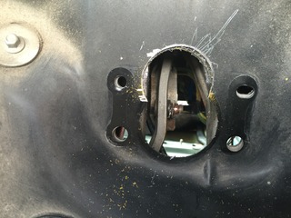
The 2.0” hole drilled in the firewall allows the use of the upper two holes that the brake booster bracket utilized and allows a master cylinder to bolt up.
This arrangement allows for a 6 to 1 pedal ratio. With a true 6 to 1 pedal ratio and using the upper bolt holes in the firewall, you also get good pushrod alignment with the master cylinder piston.
The 31/64” hole, that will be drilled into the brake pedal arm, is good for the ˝” stud/pin to be pressed into the pedal with an optimal interference fit with zero stud/pin play.
To utilize the ˝” stud/pin that is pressed into the brake pedal arm, I made a custom clevis with a ˝” hole for the stud/pin. The clevis is machined to use a 5/16” diameter pushrod with fine threads.
Here are the items used for the pushrod assembly.
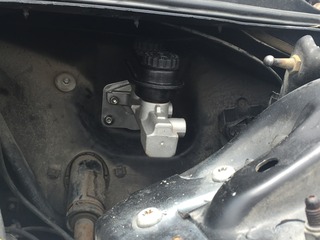
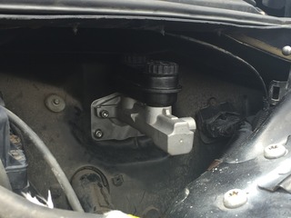
A custom CNC aluminum plate was machined to cover up the original power booster hole and allow most GM, Ford, or Mopar style master cylinder to be utilized in the upper holes. A retention cup will also be fabricated and pressed into the plate to retain the pushrod so it doesn't fall out the back of the master cylinder.

http://www.camarozone.com/forum/f17/...ctures-190596/
Here is the 2.0” hole drilled in the firewall between the upper holes of the vacuum booster bracket.

The 2.0” hole drilled in the firewall allows the use of the upper two holes that the brake booster bracket utilized and allows a master cylinder to bolt up.
This arrangement allows for a 6 to 1 pedal ratio. With a true 6 to 1 pedal ratio and using the upper bolt holes in the firewall, you also get good pushrod alignment with the master cylinder piston.
The 31/64” hole, that will be drilled into the brake pedal arm, is good for the ˝” stud/pin to be pressed into the pedal with an optimal interference fit with zero stud/pin play.
To utilize the ˝” stud/pin that is pressed into the brake pedal arm, I made a custom clevis with a ˝” hole for the stud/pin. The clevis is machined to use a 5/16” diameter pushrod with fine threads.
Here are the items used for the pushrod assembly.
A custom CNC aluminum plate was machined to cover up the original power booster hole and allow most GM, Ford, or Mopar style master cylinder to be utilized in the upper holes. A retention cup will also be fabricated and pressed into the plate to retain the pushrod so it doesn't fall out the back of the master cylinder.


 05-30-2016, 07:46 AM
#2
Teching In
Thread Starter
I did some measuring of the brake pedal assembly to find out what the stock power assist, vacuum booster pedal ratio would be. I also did the calculations of the manual brake system output at the master cylinder using different pedal ratios and master cylinder bore sizes.
Stock pedal length from center of pivot point to center of pedal pad is 12.0”
BOOSTED PEDAL RATIO
Distance from center of pivot point to center of power booster pin/stud location is 3.75”
12 ÷ 3.75 = 3.2 to 1 pedal ratio
MANUAL BRAKE PEDAL RATIO
On the F-body pedal, I moved the pin/stud location up on the pedal where it was 2.0” down from the pivot point.
12 ÷ 2 = 6 to 1 pedal ratio
I wanted to make sure my manual brakes have enough pedal ratio to create the greatest amount of leverage with roughly 1.0” of master cylinder piston travel. In this case, the 6 to 1 ratio worked out to be 1.0” (give or take a 1/16 of an inch).
After reading some of the other posts on their manual brake conversion, they moved the stud up 1.0” from the power boosted pin location.
12 ÷ 2.75 = 4.4 to 1 pedal ratio
For most brake systems, a 7/8” bore master cylinder will work well and create greater pressure than the larger 1.03” bore master cylinders.
Area of master cylinder bore:
• 7/8” bore master cylinder – 0.601 square inches
• 24mm bore master cylinder – 0.701 square inches
• 1-1/32” bore master cylinder – 0.836 square inches
If 100 pounds of pressure is applied to the brake pedal and a 6 to 1 pedal ratio:
• 7/8” bore master cylinder will create 998 psi of manual pressure
• 24mm bore master cylinder will create 886 psi of manual pressure
• 1-1/32” bore master cylinder will create 720 psi of manual pressure
If 100 pounds of pressure is applied to the brake pedal and a 4.4 to 1 pedal ratio:
• 7/8” bore master cylinder will create 732 psi of manual pressure
• 24mm bore master cylinder will create 628 psi of manual pressure
• 1-1/32” bore master cylinder will create 528 psi of manual pressure
VACUUM BOOSTED BRAKES PSI
If 100 pounds of pressure is applied to the brake pedal and a 3.2 to 1 pedal ratio:
• 24mm (stock size) secondary bore master cylinder will create 456 psi of manual pressure
• Area of a 9.0” dual diaphragm vacuum booster – 127.12 square inches
• 18 in Hg of vacuum converted to psi – 8.8 psi
• 127.12 square inches multiplied by 8.8 psi equals 1119 psi of vacuum boosted pressure
• 456 psi of manual pressure plus 1119 psi of vacuum boosted pressure is 1575 psi of pressure
Hopefully the vacuum boosted pressure is accurate. I am assuming that both diaphragms have the same area.
05-30-2016, 07:57 AM
#3
Teching In
Thread Starter
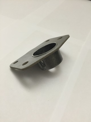
Here are different views the finished manual brake adapter plate if looking at it from the engine bay side. A pushrod retention cup is added to make sure the pushrod does not fall away from the back of the master cylinder piston if brake fluid pressure is lost. The “bump” at the bottom of the adapter plate is to completely cover the hole that the brake booster bracket used.
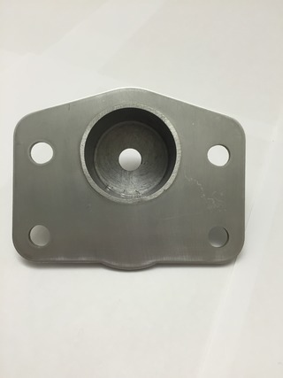

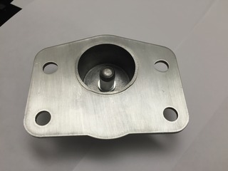
The below picture is the backside of the adapter plate that will mount against the firewall. The pushrod retention cup will install through the 2.0" hole drilled in the firewall.

The below picture is the matching gasket for the manual brake adapter plate. The gasket will be sandwiched between the firewall after it is slid over the top of the retention cup in the above picture.

The below picture is the manual brake adjustable pushrod installed in the retention cup. The pushrod has provisions to keep it captured inside the pushrod retention cup. You would see this view from the engine bay before the master cylinder is installed and after you installed your adjustable pushrod assembly to the brake pedal arm.
The below picture is the manual brake adjustable pushrod installed in the cup. You would see this view from under the dash after the adjustable pushrod assembly is installed on the brake pedal arm.

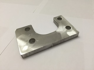
The below picture is the 1/2" thick aluminum firewall brace. It is installed under the dash, between the firewall and the brake pedal assembly bracket. The firewall brace is extended toward the driver side and bottom do take advantage of the stamped portion of the firewall. It significantly reduces firewall flex.


The below picture is the backside of the adapter plate that will mount against the firewall. The pushrod retention cup will install through the 2.0" hole drilled in the firewall.

The below picture is the matching gasket for the manual brake adapter plate. The gasket will be sandwiched between the firewall after it is slid over the top of the retention cup in the above picture.

The below picture is the manual brake adjustable pushrod installed in the retention cup. The pushrod has provisions to keep it captured inside the pushrod retention cup. You would see this view from the engine bay before the master cylinder is installed and after you installed your adjustable pushrod assembly to the brake pedal arm.

The below picture is the manual brake adjustable pushrod installed in the cup. You would see this view from under the dash after the adjustable pushrod assembly is installed on the brake pedal arm.

The below picture is the 1/2" thick aluminum firewall brace. It is installed under the dash, between the firewall and the brake pedal assembly bracket. The firewall brace is extended toward the driver side and bottom do take advantage of the stamped portion of the firewall. It significantly reduces firewall flex.
 05-30-2016, 08:13 AM
#4
Teching In
Thread Starter
Below is an analysis using the Brake Torque Calculator found on Pro-Touring.com. This calculator will give you an idea of what brake torque is for a certain front and rear setups. I am just going to show the changes from the stock, forth generation front "LT1" f-body brake system and compare them to a stock LS1 Camaro brake swap, a LS1 Camaro brake swap with Corvette calipers
Page 7, Post #140
Brake sizing and selection tutorial featuring Ron Sutton and Tobin of KORE3 - Page 7
This entire post is a really good read if you are interested about brakes.
Here are the inputs that are the same for ALL different types of brake systems shown below.
• 6 to 1 pedal ratio
• 26” tall tire
• 100 ft/lb pedal pressure
• Manual Brakes – NO POWER ASSIST
• Pad Coefficient of Friction - .45
• Use of stock type (tandem) master cylinder
__________________________________________________ __
Stock LS1 Camaro/Firebird Front Brake System
• Rotor Diameter – 12”
• 7/8” Bore Master Cylinder Area - .601 sq-in
• Line Pressure – 998 psi
• Front Caliper Piston Area – 4.931 sq-in
• Front Clamping Pressure – 4921 pounds
• Front Rotor Torque – 1107 ft/lb
• Tire Forces – 1022 lb
__________________________________________________ __
4th Generation “LT1” F-body Front Brake System
• Rotor Diameter – 10.94”
• 7/8” Bore Master Cylinder Area - .601 sq-in
• Line Pressure – 998 psi
• Front Caliper Piston Area – 4.909 sq-in
• Front Clamping Pressure – 4899 pounds
• Front Rotor Torque – 1006 ft/lb
__________________________________________________ __
Stock LS1 Camaro/Firebird Front Brake System with Corvette Calipers with 21mm bore master cylinder
• Rotor Diameter – 12”
• 21mm Bore Master Cylinder Area - .537 sq-in
• Line Pressure – 1117 psi
• Front Caliper Piston Area – 3.994 sq-in
• Front Clamping Pressure – 4461 pounds
• Front Rotor Torque – 1004 ft/lb
• Tire Forces – 927 lb
__________________________________________________ __
Stock G-body/S10/3rd Generation F-body Front Brake System
• Rotor Diameter – 10.5”
• 7/8” Bore Master Cylinder Area - .601 sq-in
• Line Pressure – 998 psi
• Front Caliper Piston Area – 4.909 sq-in
• Front Clamping Pressure – 4899 pounds
• Front Rotor Torque – 964 ft/lb
• Tire Forces – 890 lb
__________________________________________________ __
Stock LS1 Camaro/Firebird Front Brake System with Corvette Calipers with 7/8” bore master cylinder
• Rotor Diameter – 12”
• 7/8” Bore Master Cylinder Area - .601 sq-in
• Line Pressure – 998 psi
• Front Caliper Piston Area – 3.994 sq-in
• Front Clamping Pressure – 3986 pounds
• Front Rotor Torque – 897 ft/lb
• Tire Forces – 828 lb
Rating from best to worst:
1. LS1 Camaro / Firebird stock front brakes with 7/8" bore master cylinder.
2. LT1 Camaro / Firebird stock front brakes with 7/8” bore master cylinder.
3. LS1 Camaro / Firebird front brakes with Corvette brake calipers and a 21mm bore master cylinder. NOTE: A 21mm master cylinders are fairly rare and hard to find.
4. Stock g-body/S10/3rd Generation F-body stock front brake system with 7/8" bore master cylinder.
5. LS1 Camaro / Firebird front brakes with Corvette brake calipers and a 7/8” bore master cylinder.
05-30-2016, 02:32 PM
#5

Glad to see someone properly engineer a manual brake solution for these cars. I tried a manual brake kit from a vendor here, and it was a flaming piece of trash. Pedal ratio, pushrod alignment - it was all horrible. Might have been ok to stop a drag car after a run, but I wouldn't trust my life with it.
Is this something you will be selling?
Is this something you will be selling?
05-31-2016, 02:16 PM
#6
Teching In
Thread Starter
Glad to see someone properly engineer a manual brake solution for these cars. I tried a manual brake kit from a vendor here, and it was a flaming piece of trash. Pedal ratio, pushrod alignment - it was all horrible. Might have been ok to stop a drag car after a run, but I wouldn't trust my life with it.
Is this something you will be selling?
Is this something you will be selling?
The only downside to running this manual brake setup is the hole in the firewall that will need to be cut out. This modification is not reversible unless you weld back in a patch panel.
The hole is to allow to mount the master cylinder higher on the firewall which allows a higher pedal ratio (better leverage) AND the correct/maximum amount of master cylinder piston travel.
My goal with this was to get the best pedal ratio with the correct amount of master cylinder piston travel. This "KIT" will achieve the goals set. They only thing now would be to select a master cylinder bore that matches your front and rear brake calipers.
Usually the correct master cylinder is one size smaller than the factory size. LS1 Camaro/Firebird has a 1.0” bore master cylinder. With 4 wheel disc brakes, the smallest you want to run is a 7/8” bore. This will give a longer pedal travel, but it also gives the maximum line pressure. If you want a slightly firmer pedal, you could go with a 24mm master cylinder, but you will lose roughly 150 lbft of brake torque at 100 lbft of pressure on the brake pedal from the driver. For most brake systems, you will not need anything larger than 7/8” bore master cylinders.


