When you click on links to various merchants on this site and make a purchase, this can result in this site earning a commission. Affiliate programs and affiliations include, but are not limited to, the eBay Partner Network.
FWIW...When I painted my spindles, I taped off all mounting areas as that was how they were from the factory.
It would have flash rusted if I didn't paint them, I don't think the layer of paint on the mounting surfaces will cause any issues and if it does I'll sand it off.
They will probably self-clearance when you put the fasteners through. Just watch the threads to make sure they are not clogged before tightening. Another quick way to block off holes is to jam some clay in there before you paint (careful, as some oil-based clays may cause adhesion issues, so test first).
So I got my upper arms all completed tonight, I'll start the write up after this. I was doing some research on the lower bushings, specifically the vertical ones. The ones that came off my 94 are solid all the way around, however, the new Moog bushings have two notches in them so I was seeing which way these are supposed to be oriented in the arm.
While I was researching, I came across a pretty good video on the Moog problem solver. After seeing this video, it seems this bushing is more like a rod end or ball joint than a bushing. It's something I can definably see being a benefit on my car for what it's used for. I might see if I can order some and get them here by the weekend.
Update: I ended up pulling the trigger and ordering two problem solvers, they should be here no later than Friday.
Time to assemble the upper control arms. Parts you'll need.
Moog Balljoint, Front Uper - K6462 Moog Control Arm Bushing Kit, Front Upper - K6689
First off, tape the upper arms to avoid unnecessary scratches.
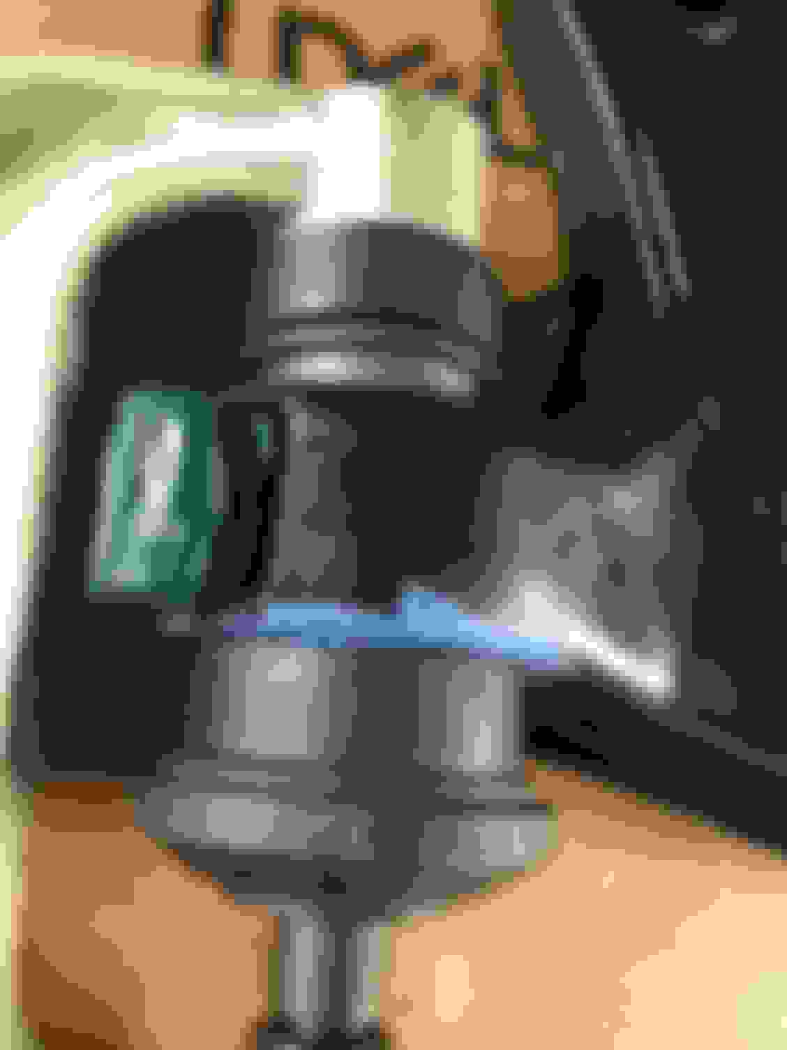
I kept the bushings in the freezer overnight to aid in installation. Put them in as far and strait as possible by hand before mocking up the press.
Spacers are also very important here. After I was done pressing in the bushings, the spacers were tight in the arms. Iff they weren't there, there's a good chance the arm would collapse in on itself. I used the same washers in electrical tape that I used when I disassembled the arms.
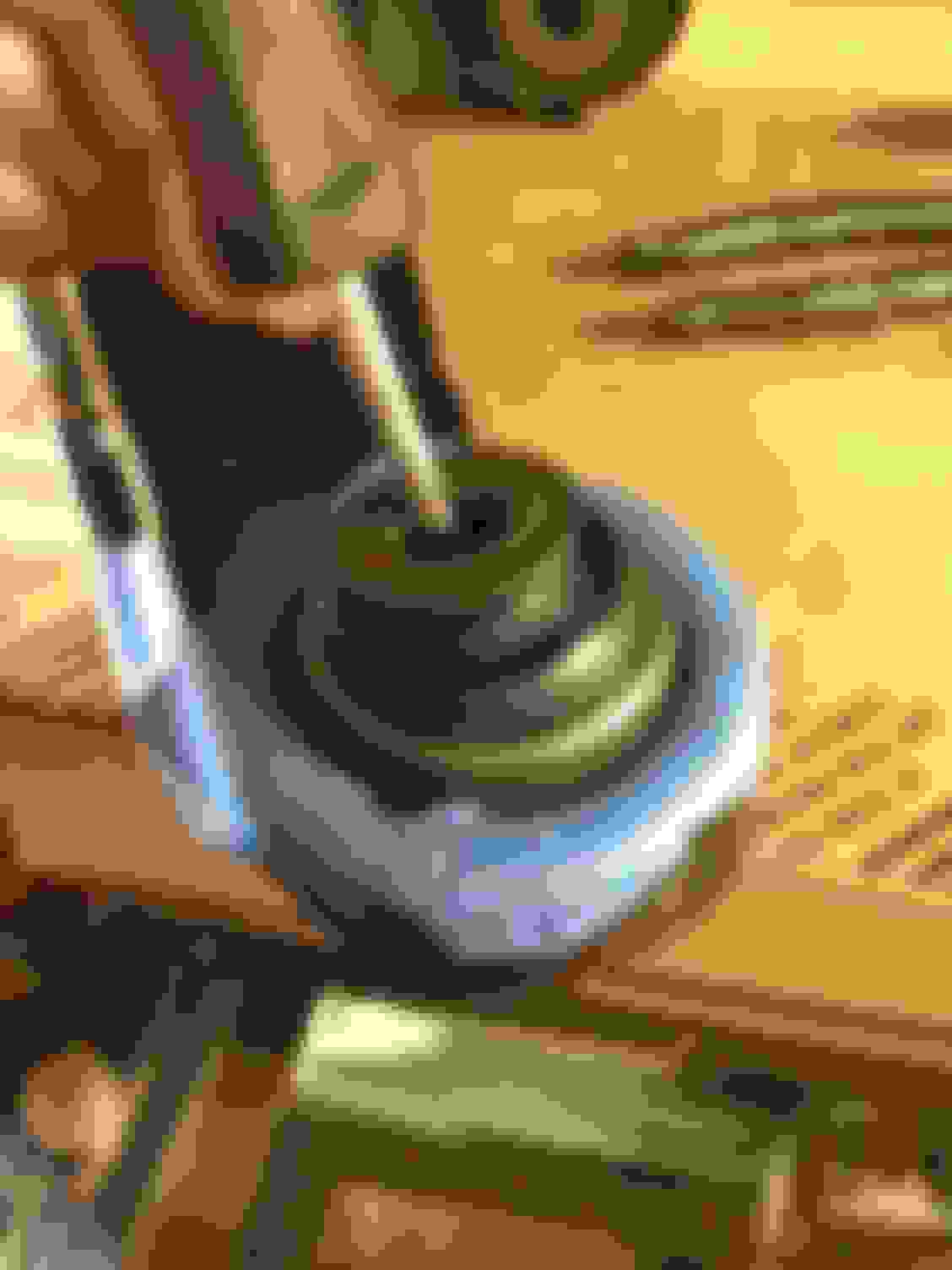
Once the press is mocked up and you start cranking, the rubber that comes out around the edge of the bushing will squeeze down. The first one is always the scariest. Once the rubber is squeezed, the bushing will start to slide in with every crank. Get it nice and snug so the lip of the bushing is just about flush with the arm.
Next up is ball joint time. Here is everything you should have with your Moog ball joint.
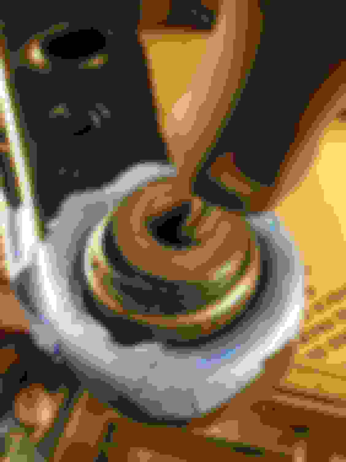
The actual ball joint gets set in from the top of the arm.
Next, the boot goes on from the bottom. Take note that there is specific orientation this boot goes one, it is labeled with what side faces inboard. I may have had this wrong in the photo below but I fixed it before tightening everything up.
Then goes on the boot retainer
After that goes on the nuts and bolts. I put the bolts in from the bottom of the arm because that's how they're shown on Moog's instructions. Snug them all up and torque to 14 ft/lbs.
Out with the old, in with the new.
Note that there is also a grease fitting that screws into the top of the ball joint, I'm going to install and grease when it's on the car. Obviously there is also a cotter pin and crown nut included with the ball joint that obviously needs to be installed on the car. Next up are the lowers.
Last edited by StoneColdLT1; 06-07-2017 at 09:31 AM.
Reason: typo correction
So I got my upper arms all completed tonight, I'll start the write up after this. I was doing some research on the lower bushings, specifically the vertical ones. The ones that came off my 94 are solid all the way around, however, the new Moog bushings have two notches in them so I was seeing which way these are supposed to be oriented in the arm.
While I was researching, I came across a pretty good video on the Moog problem solver. After seeing this video, it seems this bushing is more like a rod end or ball joint than a bushing. It's something I can definably see being a benefit on my car for what it's used for. I might see if I can order some and get them here by the weekend.
Any idea where I could find some used factory arms? I like the idea of doing the prep work off the car and having it ready to just drop in
That was my idea too, I also like the idea of doing as much prep work before the car is torn apart. It's also is why I bought another LT1 for my 383 project which is the next major upgrade the car will see. I can take my sweet time building the engine and spend a weekend or two with the car off the road swapping it in.
I bought all of my arms from members in the classified section on this site. Also maybe try Ebay or Craigslist for a part out. Just make sure they're clean, the ones that came off my car are probably salvageable but they look like a nightmare to work on and clean up. Also don't get beat up on them, they're stock arms and every f body ever made came with them, they're not tubular or anything special, and most likely need bushings so don't pay an arm and a leg for them.
So......would you recommend anti-seize on the A-Arm hardware? How about a crap ton of grease on the upper shock bolt area to try to minimize the rust buildup there as well?
Time to assembly the lower arm bushings. Parts you'll need
Moog Control Arm Bushing Kit, Front Lower - K6490 Moog Control Arm Bushing Problem Solver, Front Lower Rearward/Vertical - K200790
I actually did them last night but it was such a pain and I was in no mood to do a write-up. I only did bushings as I need to make a trip back to my buddies house to use his H-frame press for the ball joints as they don't fit in the press clamp.
First was the horizontal bushing. This was easiest by far. Just like the uppers, tape to protect the arms, from the press, make sure it's straight by hand, mock up the press, put in spacers, and start cranking.
Before you crank these all the way down, look at the arms that came off the car and compare. The first one I did I cranked down all the way and I thought I screwed myself, but comparing them to the original, the inner sleeve is actually in the same position. The arms that came off the car and the arms I redid both didn't have this bushing seated all the way, but the inner sleeve seamed to be sucked in at one end and sticking out the other. I'm not sure if the bushing works itself like this overtime or what but with it seated all the way, the inner sleeve seems to be where it should be so I kept it. We'll see how it goes on the car.
Next up was the vertical bushing. As mentioned before, I decided to order a set of Moog Problem Solvers which is more like a ball joint then a bushing which I think is much better to have in that position.
Comparing it to the OEM style bushing, there are some things I noticed that are different besides the obvious design. First off, the the metal sleeve flange is much thinner and easier to bend than the OEM style bushing, which I ended up doing during installation, luckily it's also easy to bend back. Also, I test fitted the bolts in the sleeve, while all of the bolts fit snug in the other bushings, the problem solver seems to have a little play between the inner sleeve and bolt, definably more than the others. Not sure if they added space between the sleeve and bolt to avoid the common issue of a frozen bolt in this position, I'm just hoping it doesn't slap around and make noise.
Installation is pretty much the same as the other bushings but get ready for a pain, these didn't go in as easy as the others. You also can't use a spacer as there is nothing to space in this position.
Make sure to use a deeper receiver tube than shown below, this one came up a little short and was one reason why the flange got bent a little.
These you definably don't press in all the way. You need to reference the arms that come off the car in order to see how far in they need to go. A good way to do this is to sit both arms on a level surface by the bushing flange and compare height.
Once it's in about the right about, you're done. I may need to fine tune these during installation but for right now I think they're as good as they're going to get. They move just like a ball joint and are very nice. I'm excited to see how they feel on the car.
Just some of my frustration from last night. One of the problem solvers decided to start walking sideways while being pressed. What a nightmare it was to straiten this back out. I ended up using a pry bar and catching the lip of the bushing and the back of the arm to straiten it. It was not fun.
Once that nightmare was fixed, lower arms are done until I get around to my buddies press.
Today I ended up prepping and painting the inner fender wells.
First, I started by removing the the two 10mm bolts that hold the brake line brackets to the k-frame. There was a ton of dirt and rust behind them.
I was also going to remove and paint the actual perches that mount the sway bar to the chassis, but two of the four bolts go into a frame rail that I cannot access the back of, I didn't want to break loose a nut if it's back there and have no way to tighten it. That's probably not the case but I didn't want to open a can of worms so I decided to prep and paint them on the car.
Then I wire wheeled all of the rust and loose paint off.
Then sand with 320 grit and clean with some wax and grease remover.
Then put on three solid coats of VHT Roll Bar and Chassis paint. Don't forget the brake line and sway bar perches.
In addition to this, I've also put on a couple more coats of paint on the spindles and UCA mounts, and am going to clean up and paint a couple small miscellaneous brackets, nothing to great to see.
So the bushing press set that you got doesn't have big enough cups to work for the ball joints, or the C-span isn't big enough? Isn't there an industrial size setup you can borrow from autozone? I guess, not you, per se, as you have access to your friend's setup.
Do you happen to have any of the torque specs for these bolts?
Finally, I assume during re-assembly, you can put anti-sieze on all the bolts?
It has the correct cups to make it work, but the c clamp isn't big enough to fit everything between it. When I use my buddies press, we actually use all the cups out of this set. I'm not sure if Autozone has a bigger set to rent, this is one of the larger sets, TBH, I don't feel like renting tool to maybe have it work, I'll just swing by my buddies house later tonight or tomorrow after work and get it done in a few minutes.
Do you mean torque specs for the control arm bolts? I believe they're all in my Haynes manual, I can list them later when I get the chance. Wasn't to worried about them now as everything was going to stay loose/snug, until I set the cars weight on the arms. Also as the springs settle, I was going to loosen and re-tighten the control arm bolts.
I don't see why you wouldn't be able to put anti-sieze on the bolts during reassembly.
Yeah, no reason for you to rent a tool as you have your buddy, I was thinking more for those of us watching along in prep for ourselves
I was figuring the Haynes manual, but wasn't sure if they are all listed in there. My manual is in storage so i need to pick up another.
Regarding the anti-seize, I wasn't sure if some of the bolts like the a-arm bushing bolts which have nylon lock washers wouldn't want to have anti-seize on them . Definitely going to use it on the vertical bushings though!
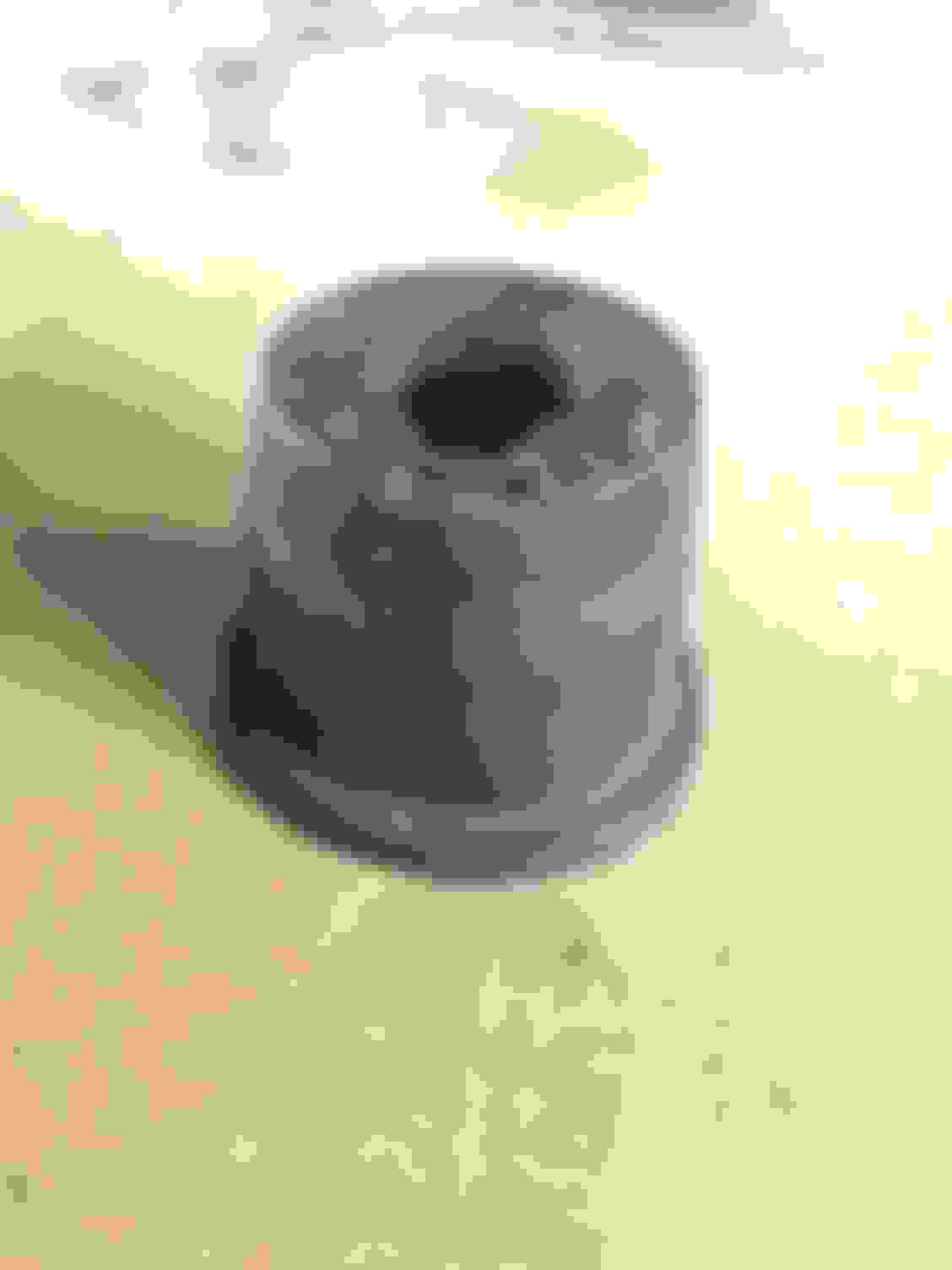
Well the press set I have I'm borrowing from the same buddy with the H-frame press, however, yesterday when I was at Advanced Auto I saw a bunch of the same brand press sets stacked behind the counter in all different sizes. I took a photo of the set I'm using, I can also take a measurement of the clamp to make sure whatever you get will work.
I will list all torque specs per the Haynes manual later tonight when I'm relaxing. With the exception of torque specs, there's not too much good info in that book for these cars so I'd save your money, especially if you just need to dig one out of storage. The only Haynes manual I had that was worth its weight was for my old Astro van, that thing was in depth but then again Astro vans never really changed between 85 and 03. The Haynes manual I've used for GM W body cars, 4th gen F bodies, 1st gen Dodge Dakotas, and GMT800 trucks were nothing to write home about, really only use them for torque specs.
So it was up for debate about whether or not to replace the inner tie rods since they were not really worn out, however, I have the new rods so I figured, what the heck. It's a pretty easy job, and since it was close to 100 degrees today, it was all I got done. Parts you'll need.
Moog Tie Rod End, Inner - EV260 ACDelco Rack and Pinion Bellow - 46A7055A
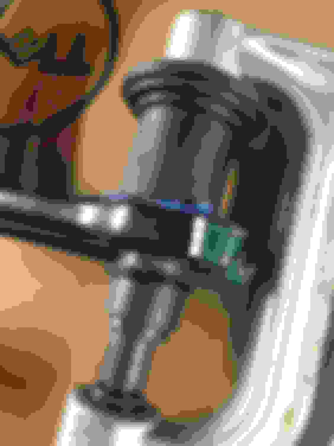
First thing to do is remove the bellow. There is some metal clip holding in the big end I just bent off with a flat head screwdriver, and a spring clip I reused holding the smaller end.
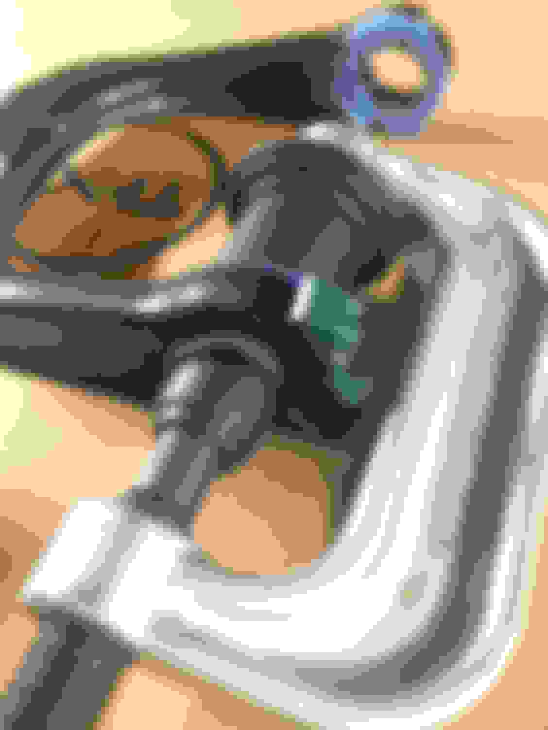
Then there is a white plastic cap that covers the notch that is used to remove the inner tie rod. This plastic cap is easily removed by hand or a flat head screwdriver.
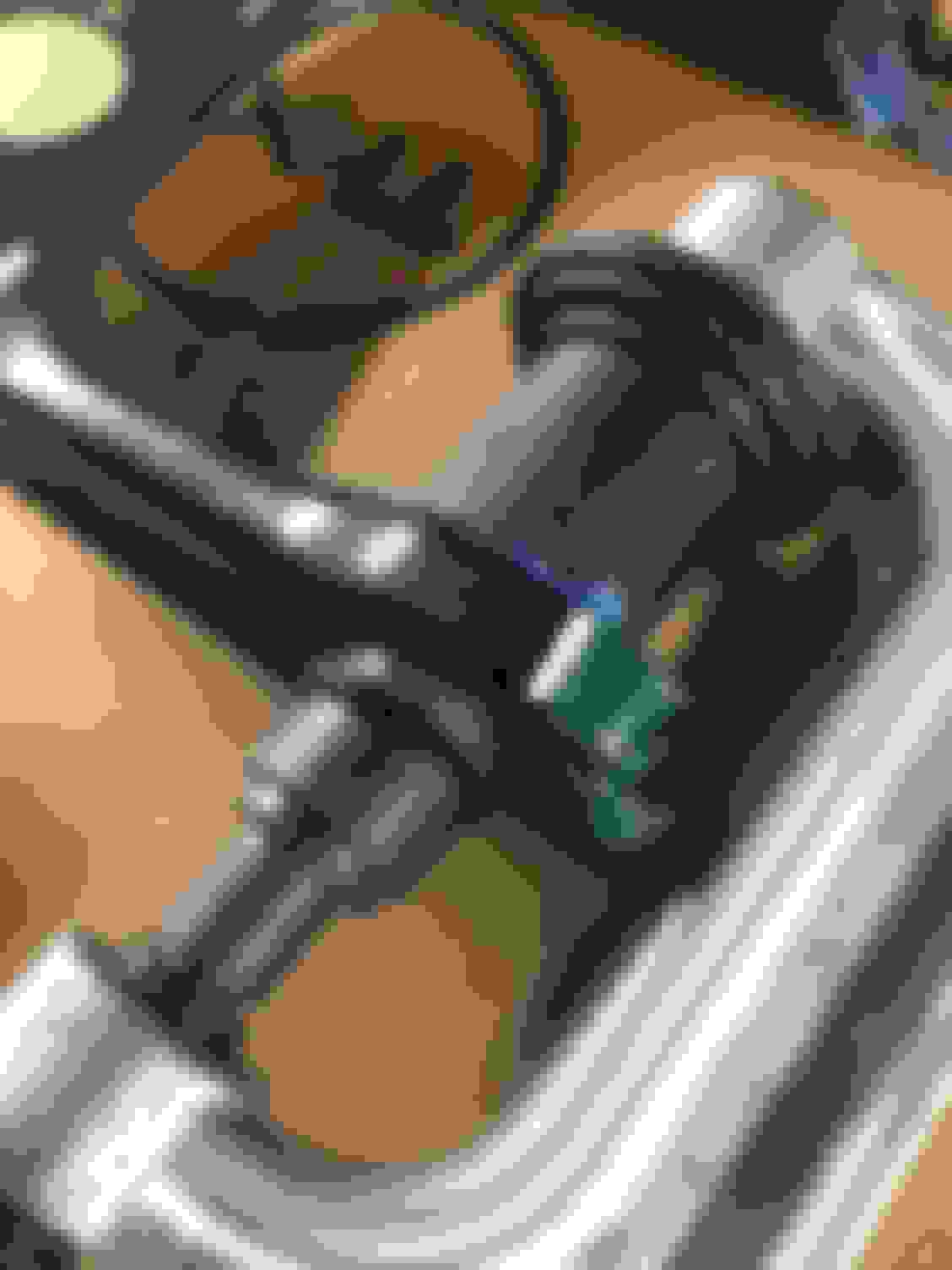
I rented a tool from Autozone to remove this. Honestly, you could probably do it with an adjustable but I figure I'd be on the safe side. Plus you can properly torque these with the tool. Why it's lime green, I have no clue.
Here is the new and old side by side. I honestly glade I decided to change these, the original weren't really worn by the new Moog's are much more smoother and nice. The old ones were over 20 years old, might as well change them while I'm in there.
For installation, put some Loctite on the threads and start screwing in by hand. Once snug, put back on the tool and torque to 74 ft-lbs. Then slide that white plastic cap back over the new tie rod.
To finish up, slide the new bellow over. Make sure it secure on the rack, and the tie rod has a small notch that holds the smaller end. The new bellow comes with some zip ties, I used the larger on fro the rack side but I reused the spring clip on the smaller size.
After that, you're done. Unfortunately I only got the passenger side done today as when I installed the driver side, I realized the new Moog inner tie rod was really stiff and made noise when I moved it, it definably wasn't greased properly or something. I'm sending it tomorrow and I'm hoping a replacement won't take too long.
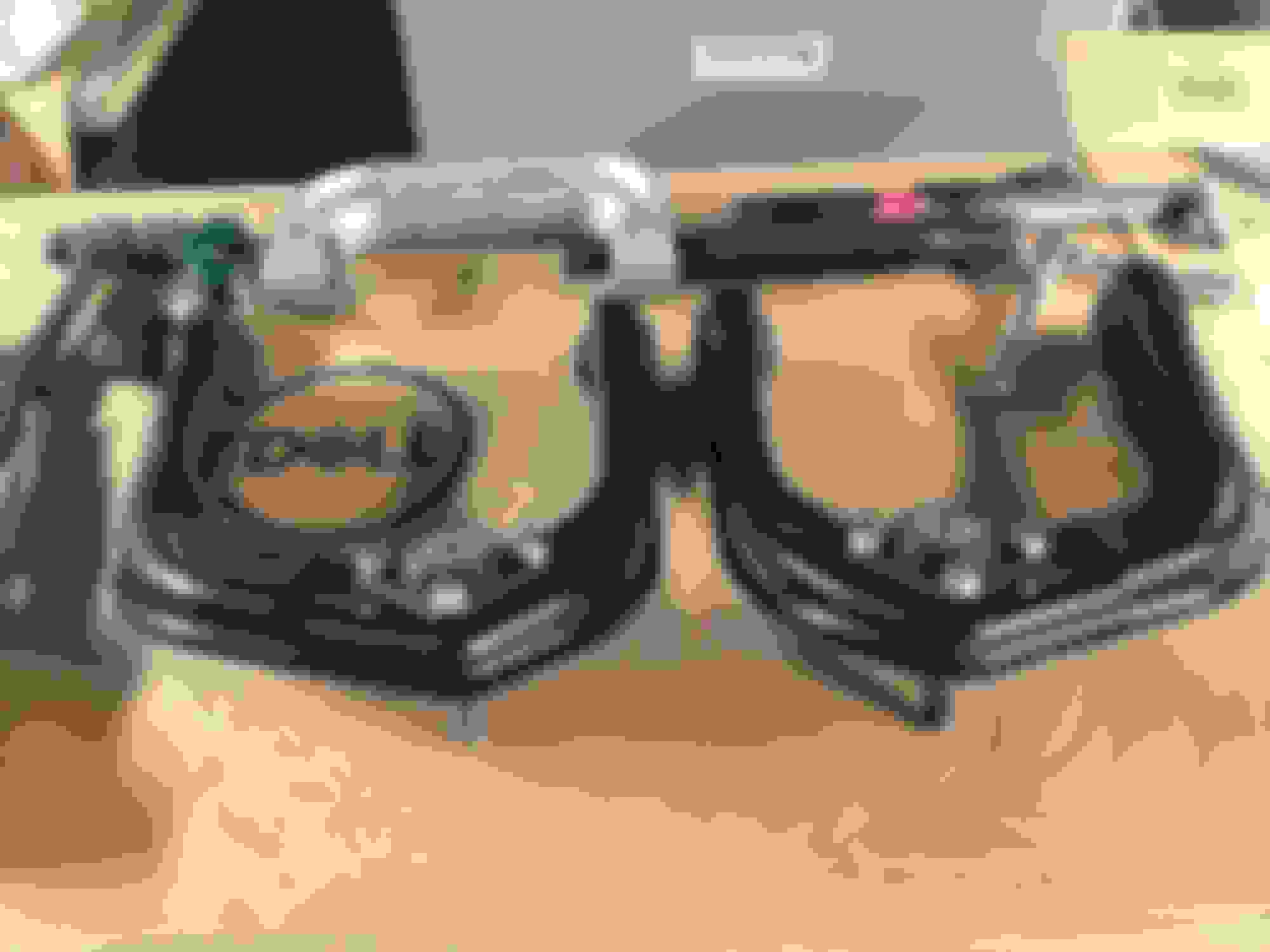
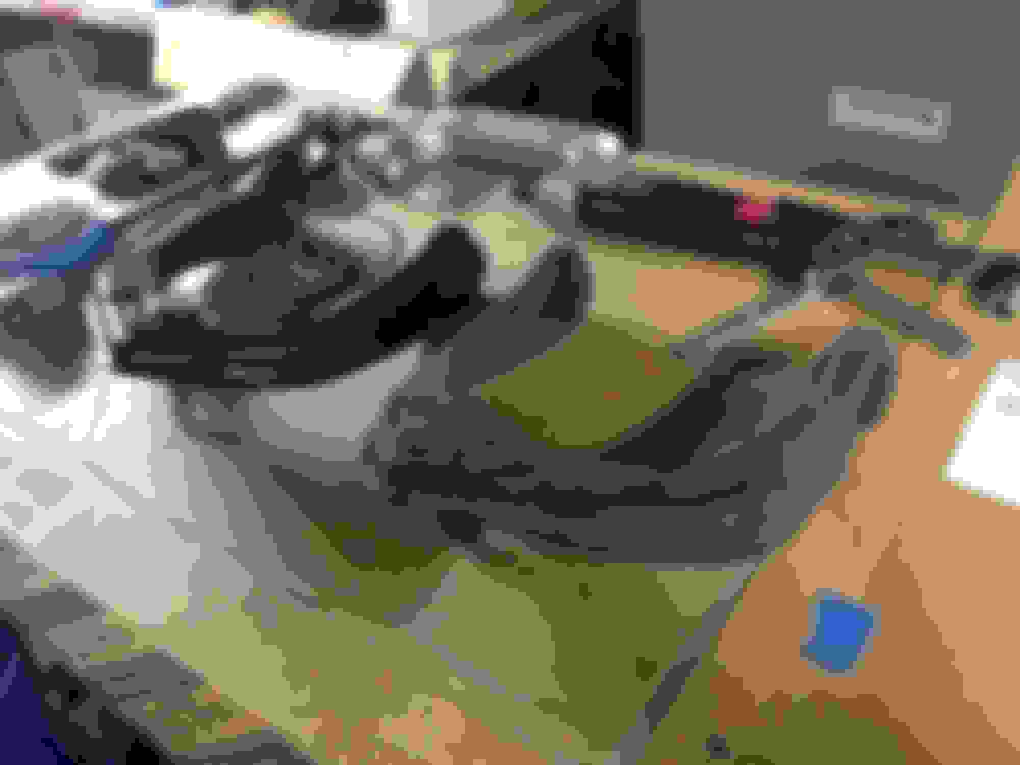
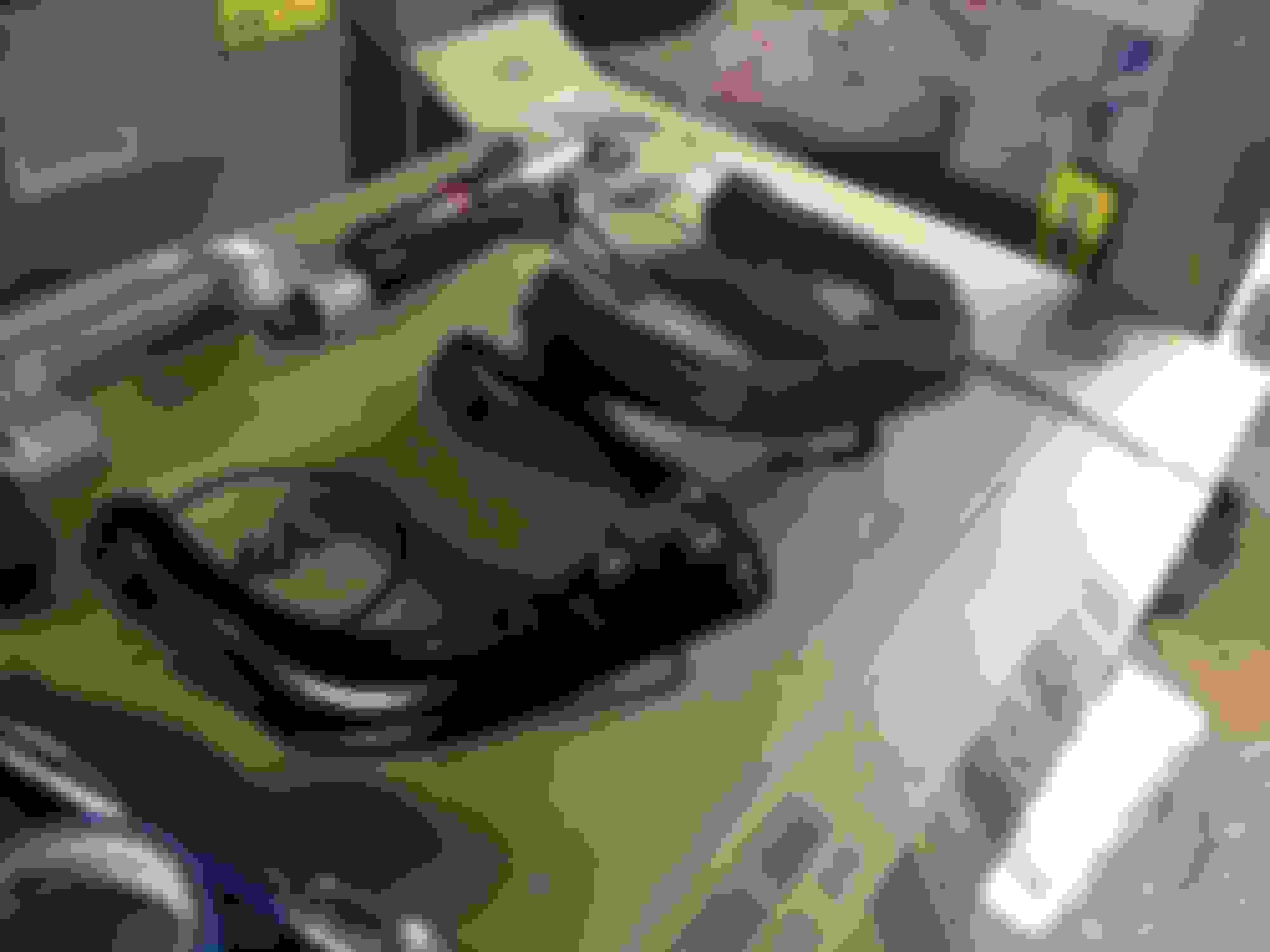
Also just for some comparison, I got my brake rotors cut this past week and had them sitting in the back of my car the entire time. I took them out and decided to compare, from left to right we have LT1, LS1, and CTS-V.
Here are the torque specifications at the beginning of the suspension and steering system chapter in my Haynes manual. All numbers are ft-lbs unless otherwise indicated.
You rock! Thx for the torque specs. I thought about replacing the inner tie rods, glad to see that yours looked to be in good shape. Looking forward to seeing the front installed and the rear coming off

 06-06-2017, 05:20 PM