When you click on links to various merchants on this site and make a purchase, this can result in this site earning a commission. Affiliate programs and affiliations include, but are not limited to, the eBay Partner Network.
Shock Absorber/Coil Spring Assemblies
Upper nuts - 32 (are these the 2 shock mount nuts accessible from the engine bay?)
Upper bolts - 37 (are these the 2 shock mount bolts accessible from the engine bay?)
Lower bolts/nuts - 48 (presume these are the 2 lower bolts that connect to the lower A-arm)
Upper Control Arms
Control arm-to-support bolts/nuts - 72 (are these the bolts going through the bushings?)
Upper control arm support nuts - 32 (are these the same as above)
Upper control arm support bolts - 37 (are these the same as above)
Okay, I just copied what was right out of the Haynes manual. You are correct with your assumptions.
The upper nuts, and upper bolts under the shock absorber/coil spring assemblies, and the upper control arm support nuts and bolts are referring to the same nuts and bolts, notice the same torque spec. These are 2 bolts and 2 nuts on each side that hold the upper spring/shock assembly and upper control arm mount to the shock tower. They are accessed from on top of the tower, under the hood. The studs and bolts actually go into the spring mount on top of the shock and the control arm support that holds the arms is just sandwiched that and the shock tower.
The lower bolts/nuts under the shock absorber/coil spring assemblies are the two bolts and nuts on each side that attach the lower end of the shock to the lower control arm.
The control arm-to-support bolt/nuts are the bolts and nuts that attach the upper control arm to the upper control arm support.
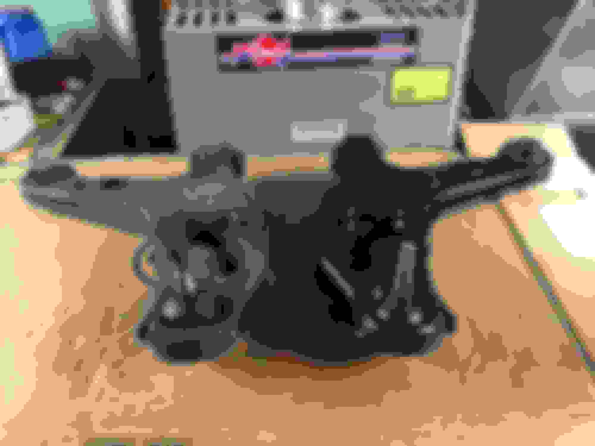
Alright, this was by far the hardest to install out of all of the bushing and ball joints put together so far. Follow along because I will give you some tips that will make this install much more painless. I also very strongly suggest the use of an H-frame press, I'm actually not sure if this would be possible with a regular ball joint clamp press. I'd be lying if I said at no time during this I wasn't considering paying a shop to finish the job. Parts you'll need.
Moog Balljoint, Front Lower - K6145T
Your ball joint should come with the actual ball joint, a rubber dust boot, a crown nut and a cotter pin. The ball joint gets pressed in from the bottom and then the boot goes on from the top.
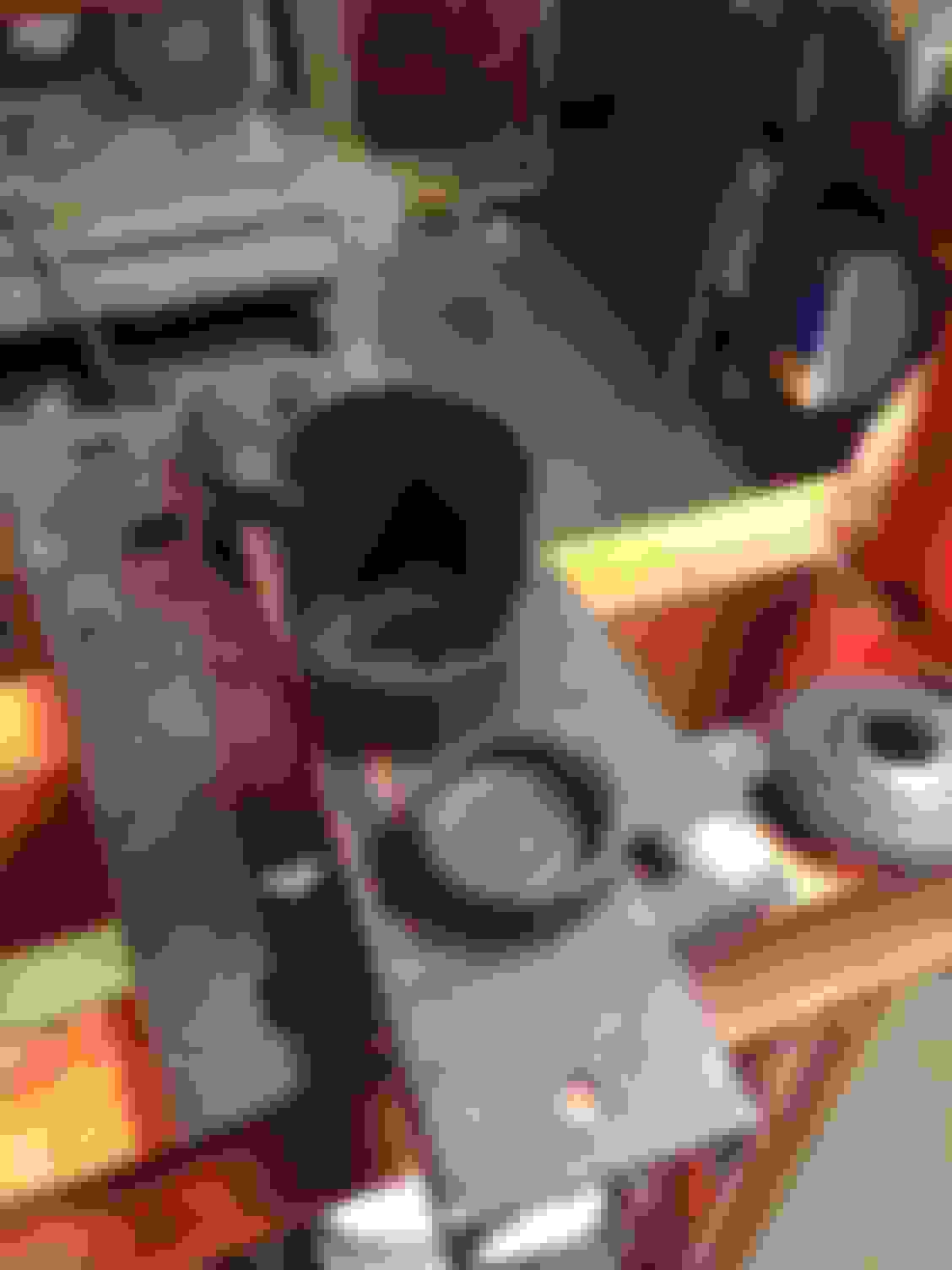
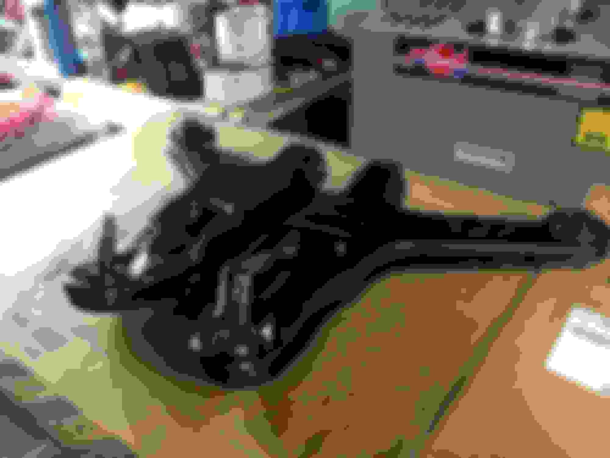
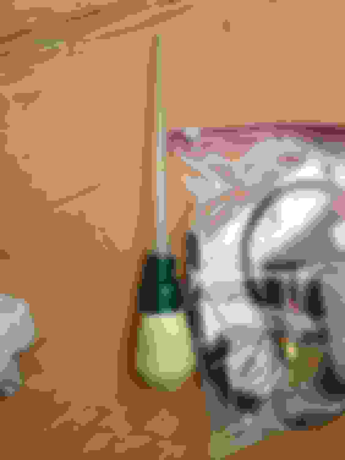
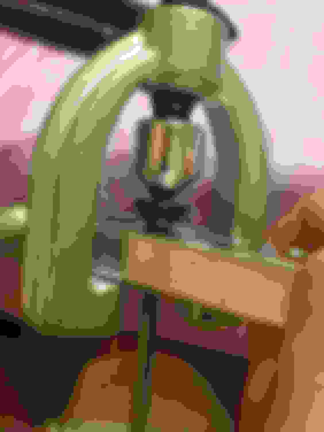
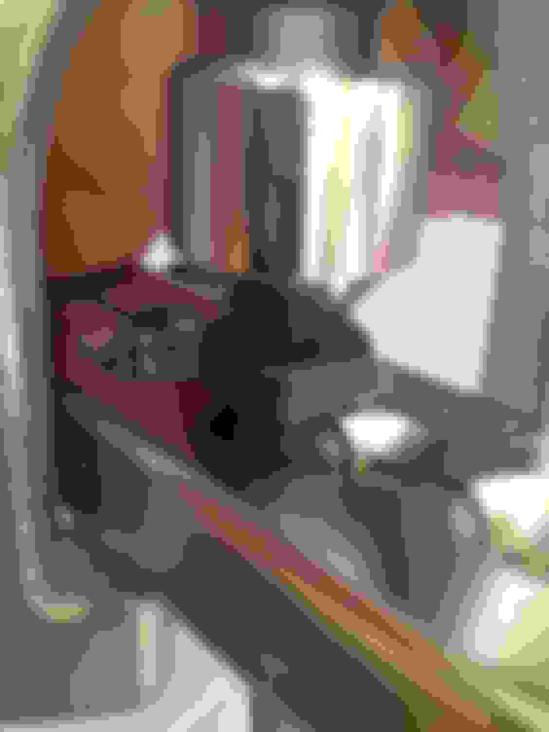
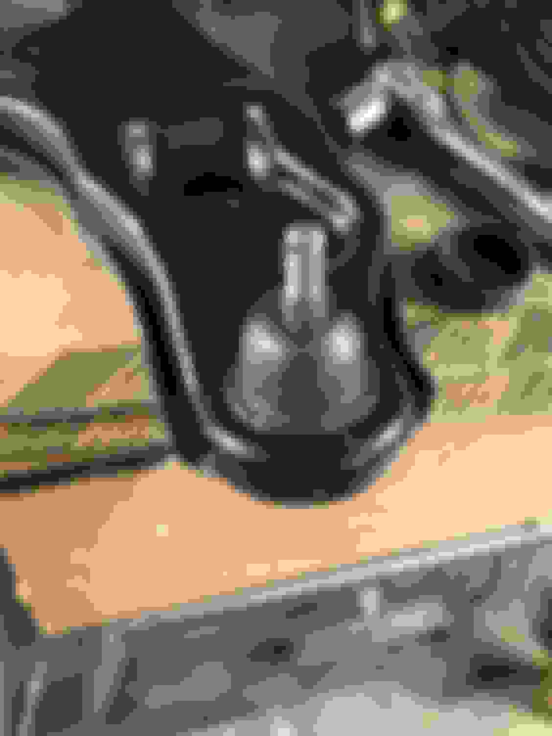
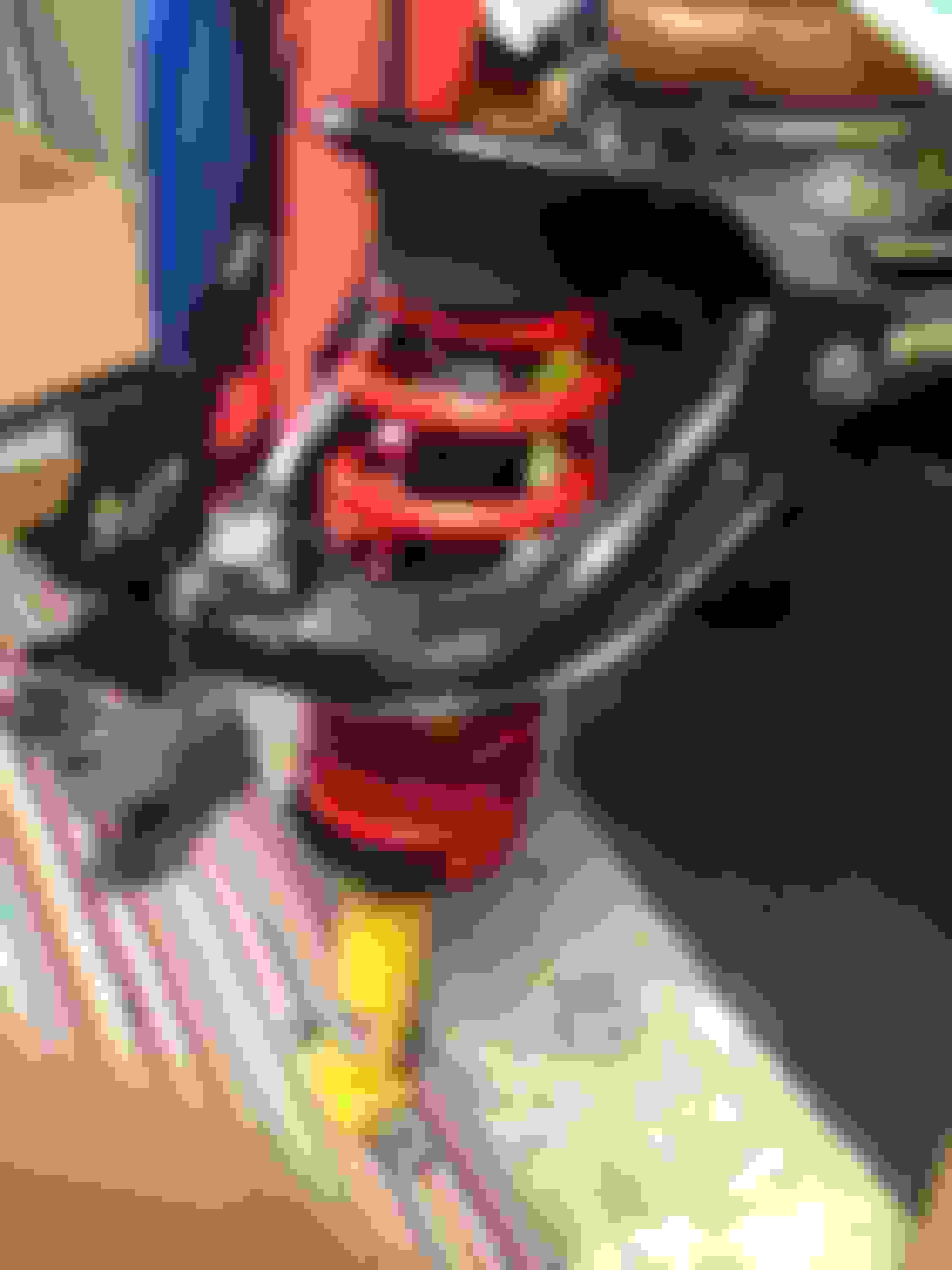
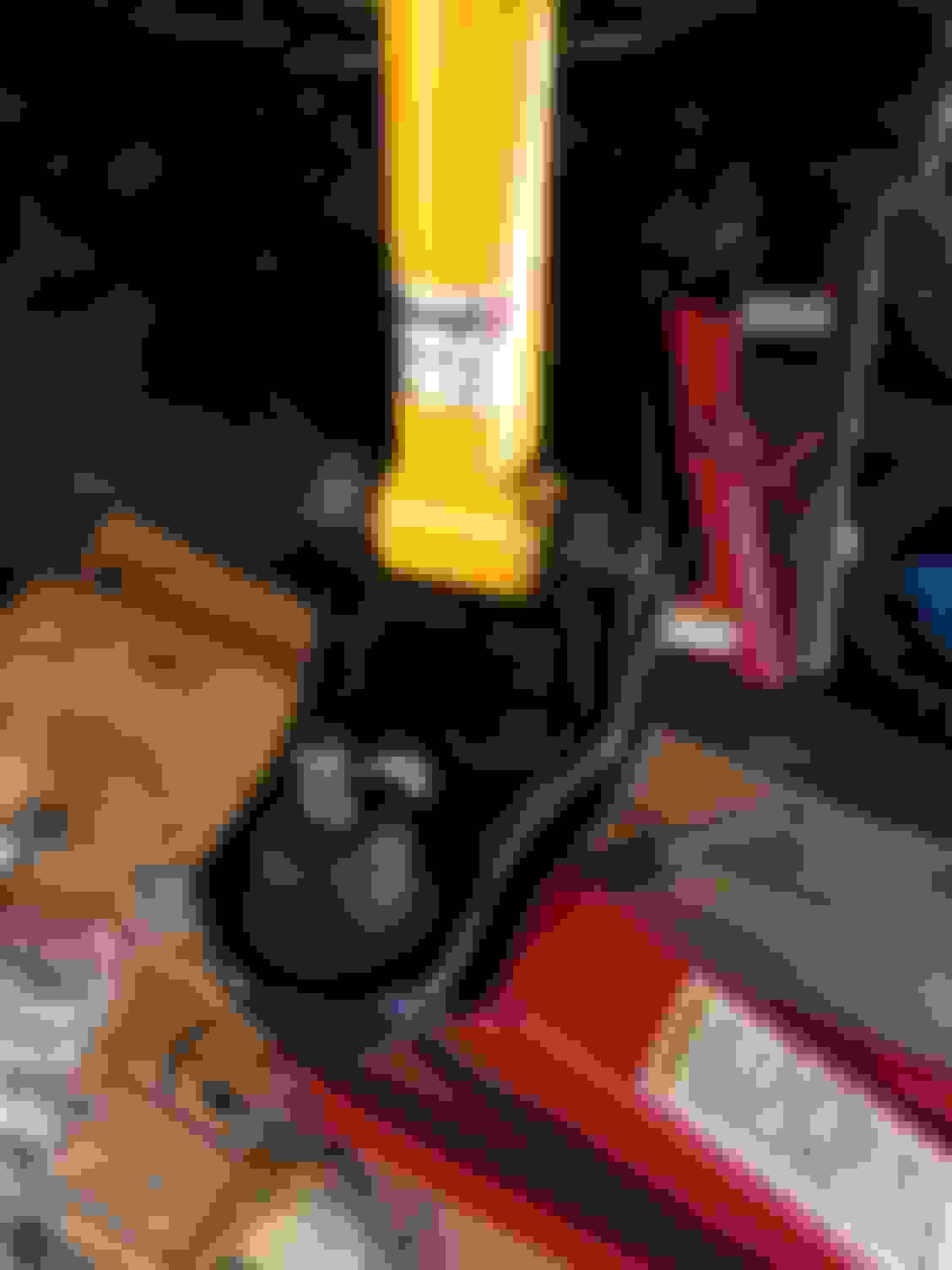
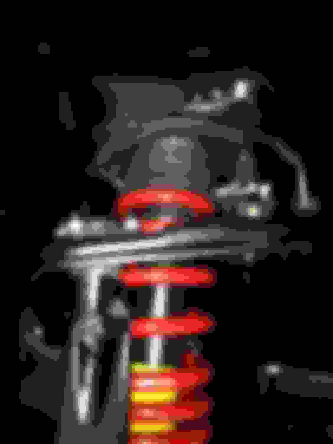
The first thing you're going to want to do is try to set this thing in there as strait as possible and mock up the press. I'd put them in the freezer from a couple minutes before you're ready to press them in. I didn't feel much of a difference but it couldn't hurt. It also doesn't do much on these but I put a couple layers of painters tape to help as much as possible.
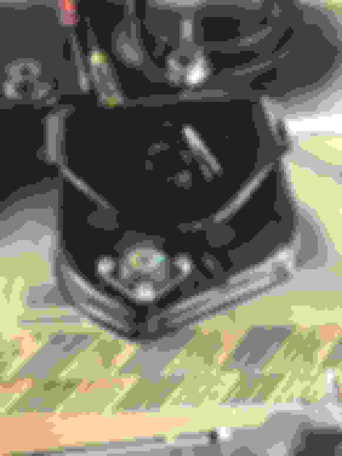
Now here's the issue, as you can see, the control arm is not flat on the side that the receiver cup needs to sit on which means you have to use one of these half round cups. The issue with these is that since the control arm isn't supported on one half, it tends to **** and send the ball joint in sideways. This isn't that big of an issue as it doesn't **** that bad, but the issue comes into play when the outside of the balljoint seats and the inside still has a gap, once that happens, the arm will start to **** before the inside of the balljoint seats, these things are in there tight. This was a real pain, and the first one we did took us a while and we kept moving the arm and trying to press on the edge of the ball joint to straiten it but the arm kept cocking.
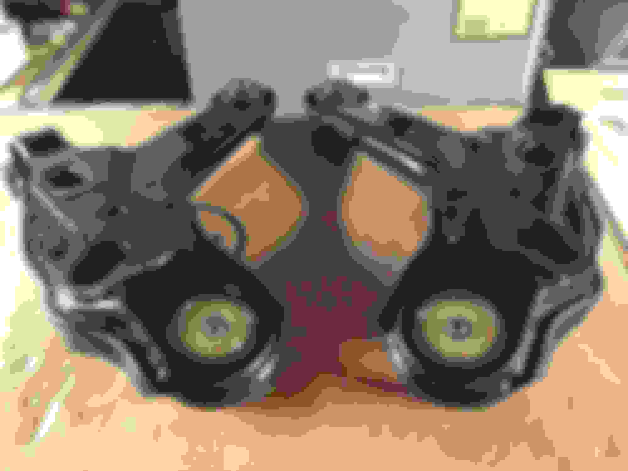
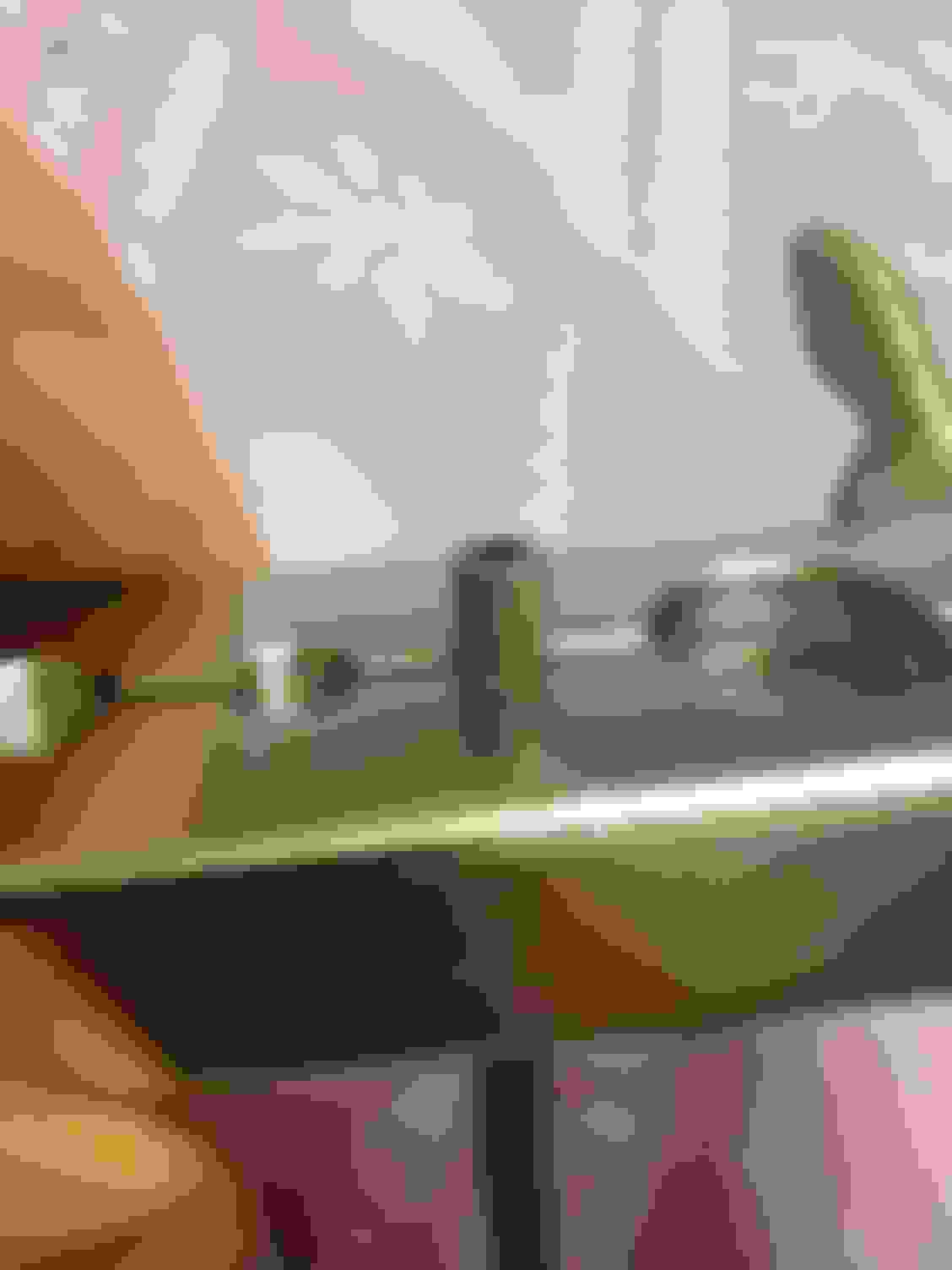
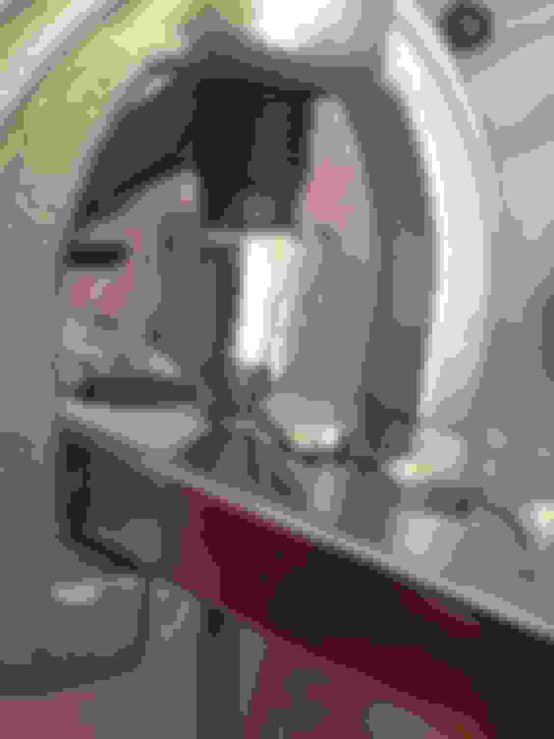
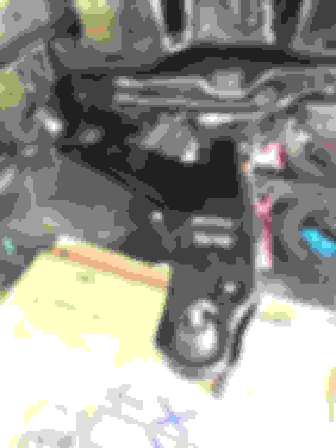
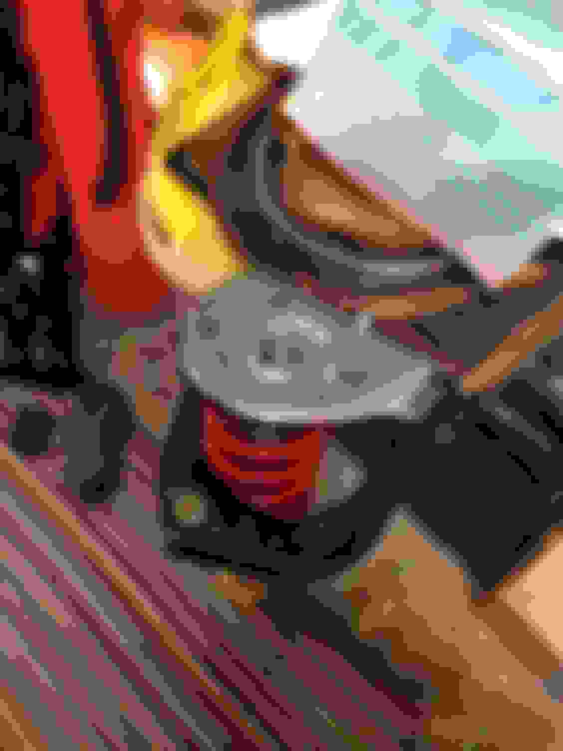
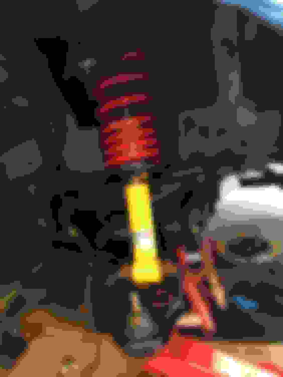
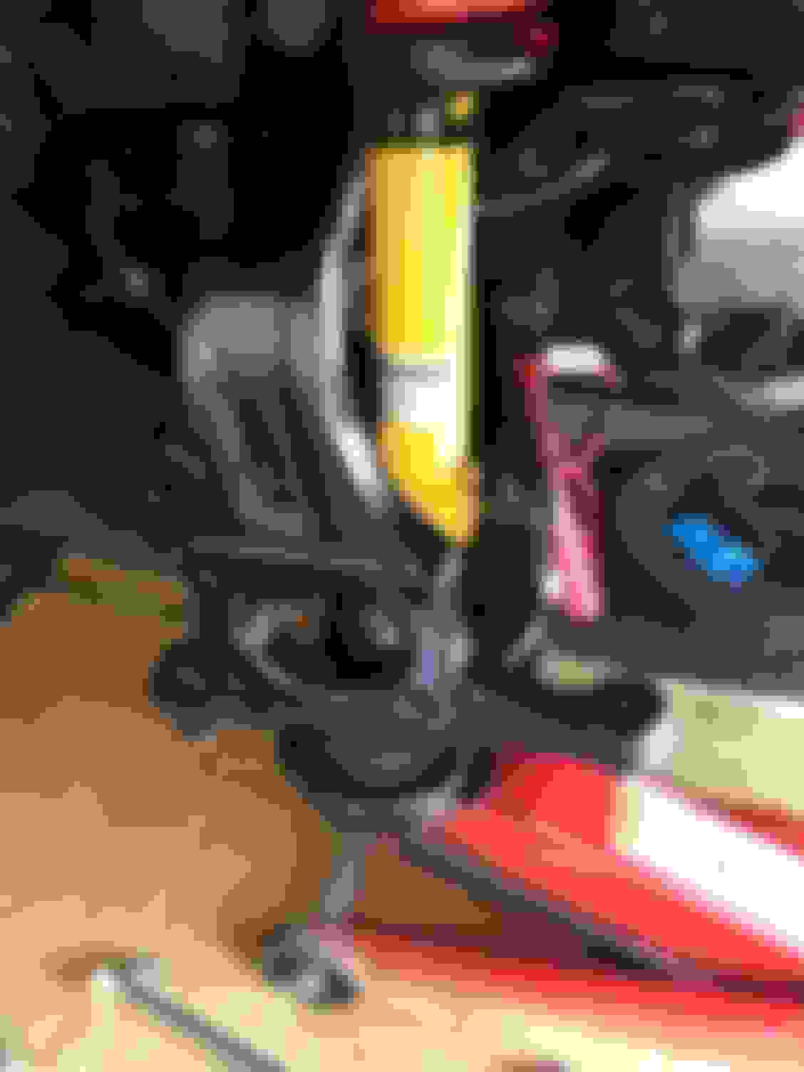
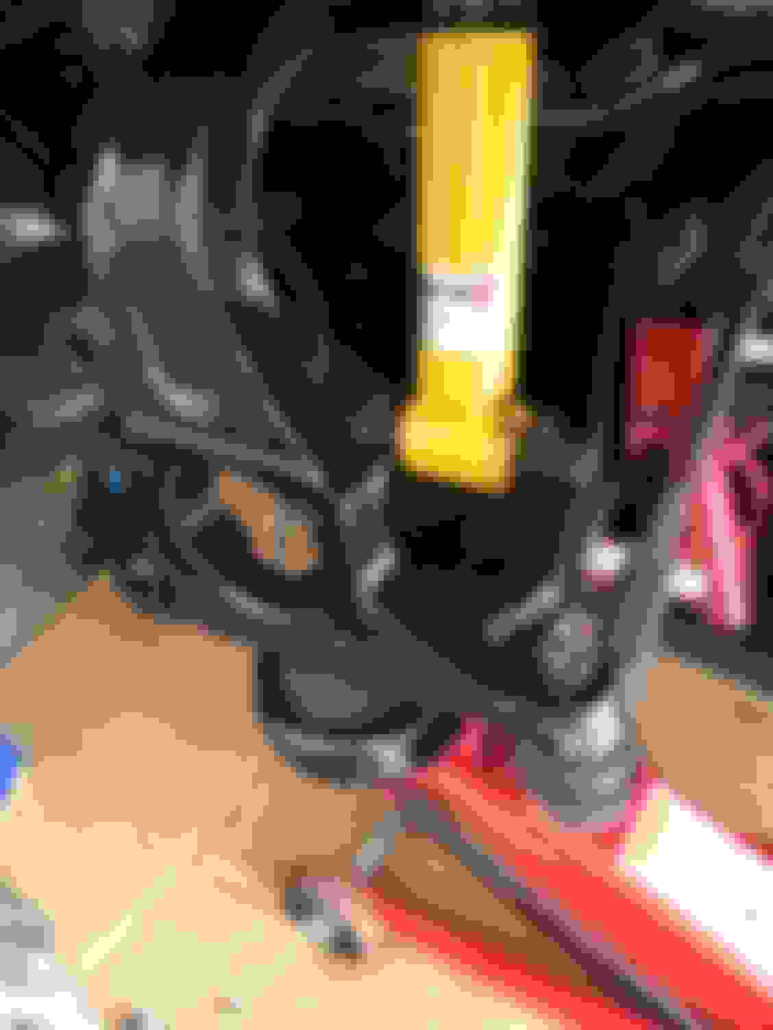
Here is the solution and is very important, you need to rig up a jig. As shown below, we took a piece of C-channel and couple shims to hold up the inside of the arm that isn't supported by the receiver cup and stops the arm from cocking while being pressed. This allows the inside of the ball joint to seat properly.
The second arm went like butter with this jig setup, I'd say it's definably needed.
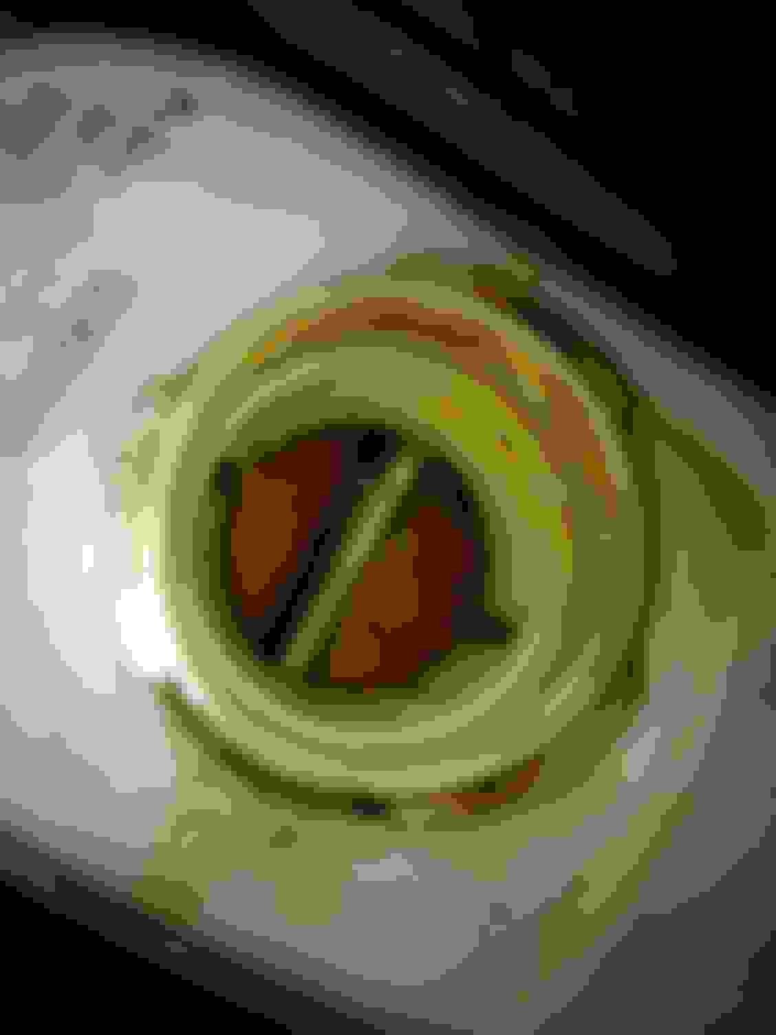
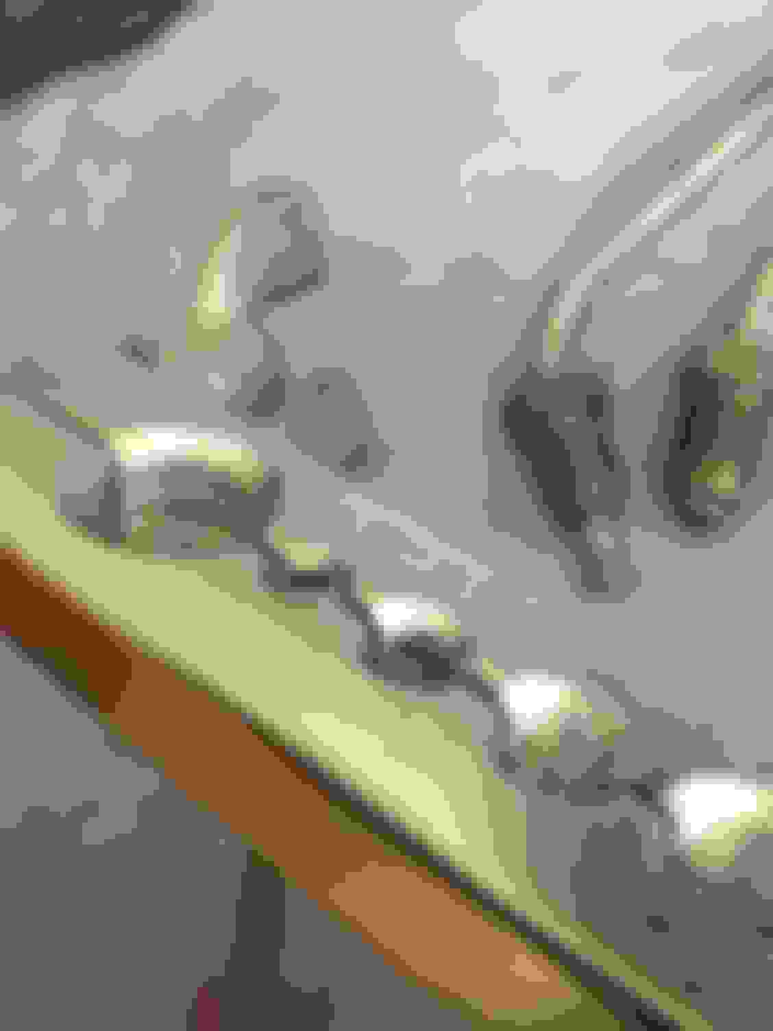
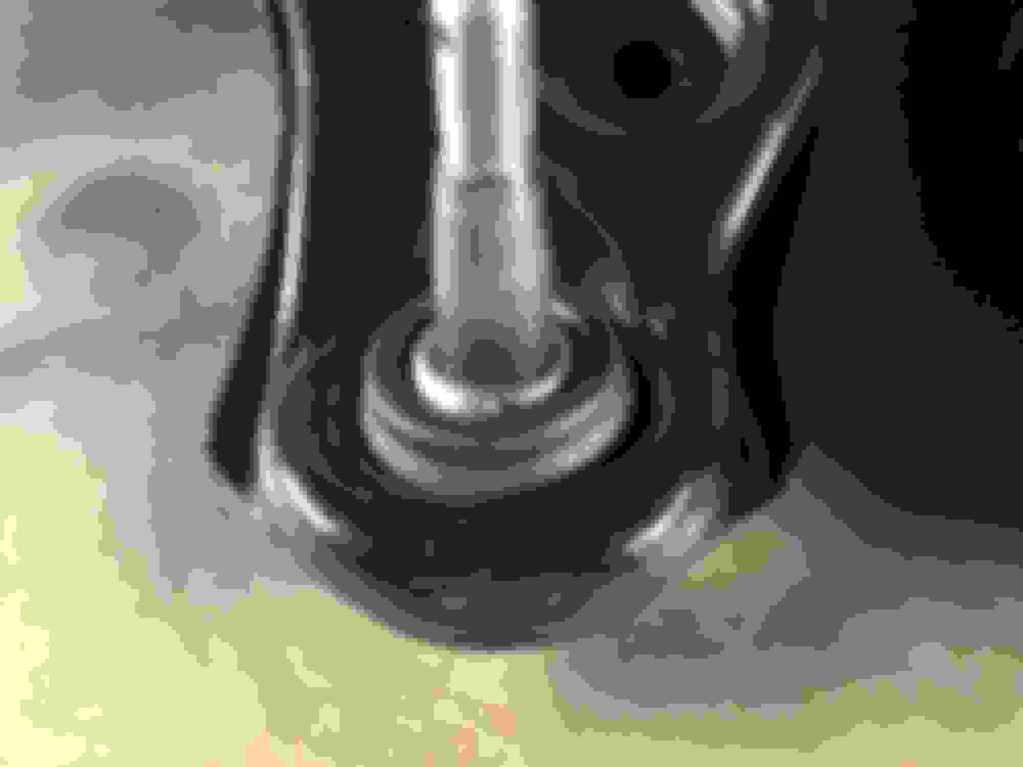
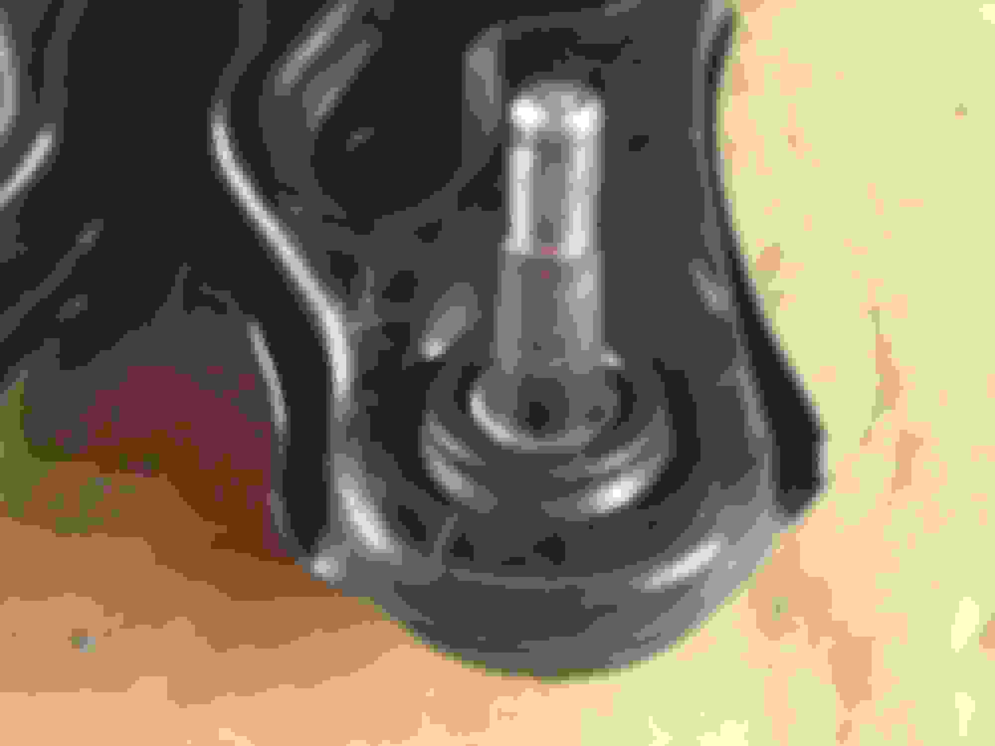
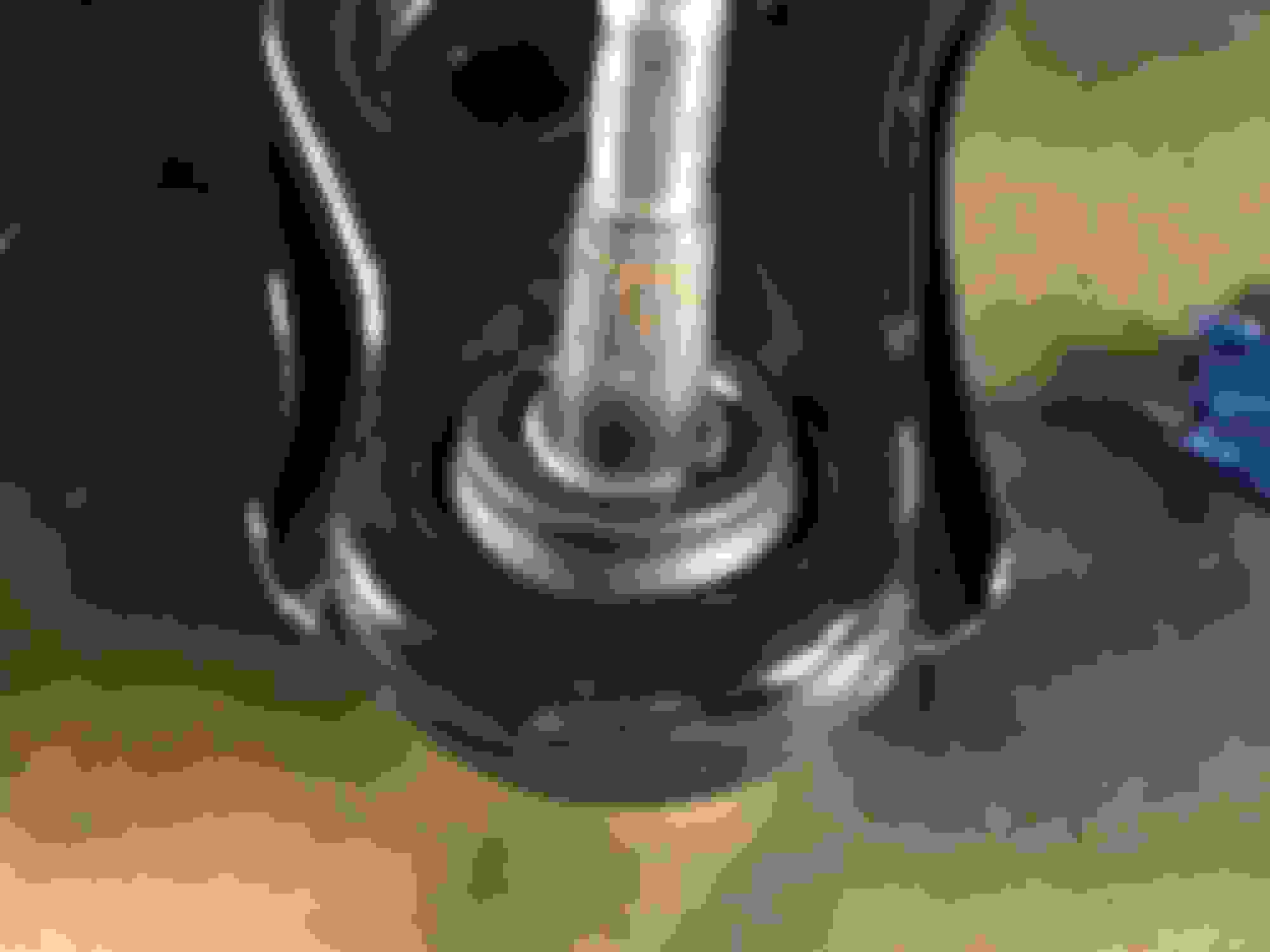
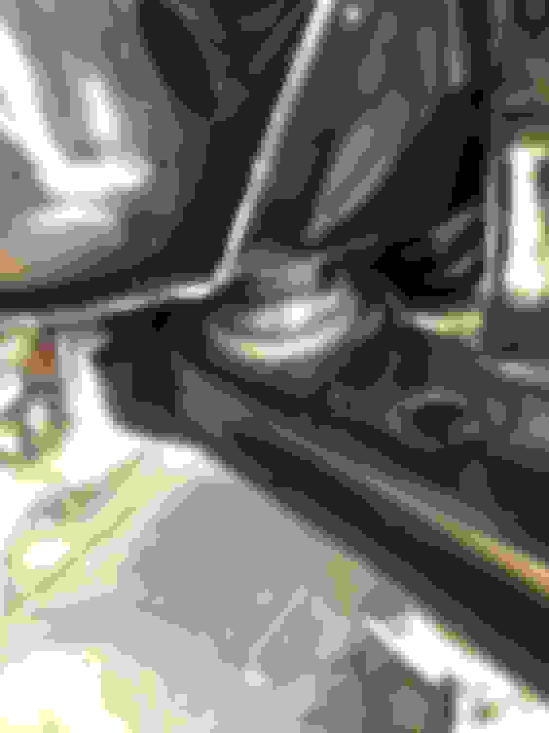
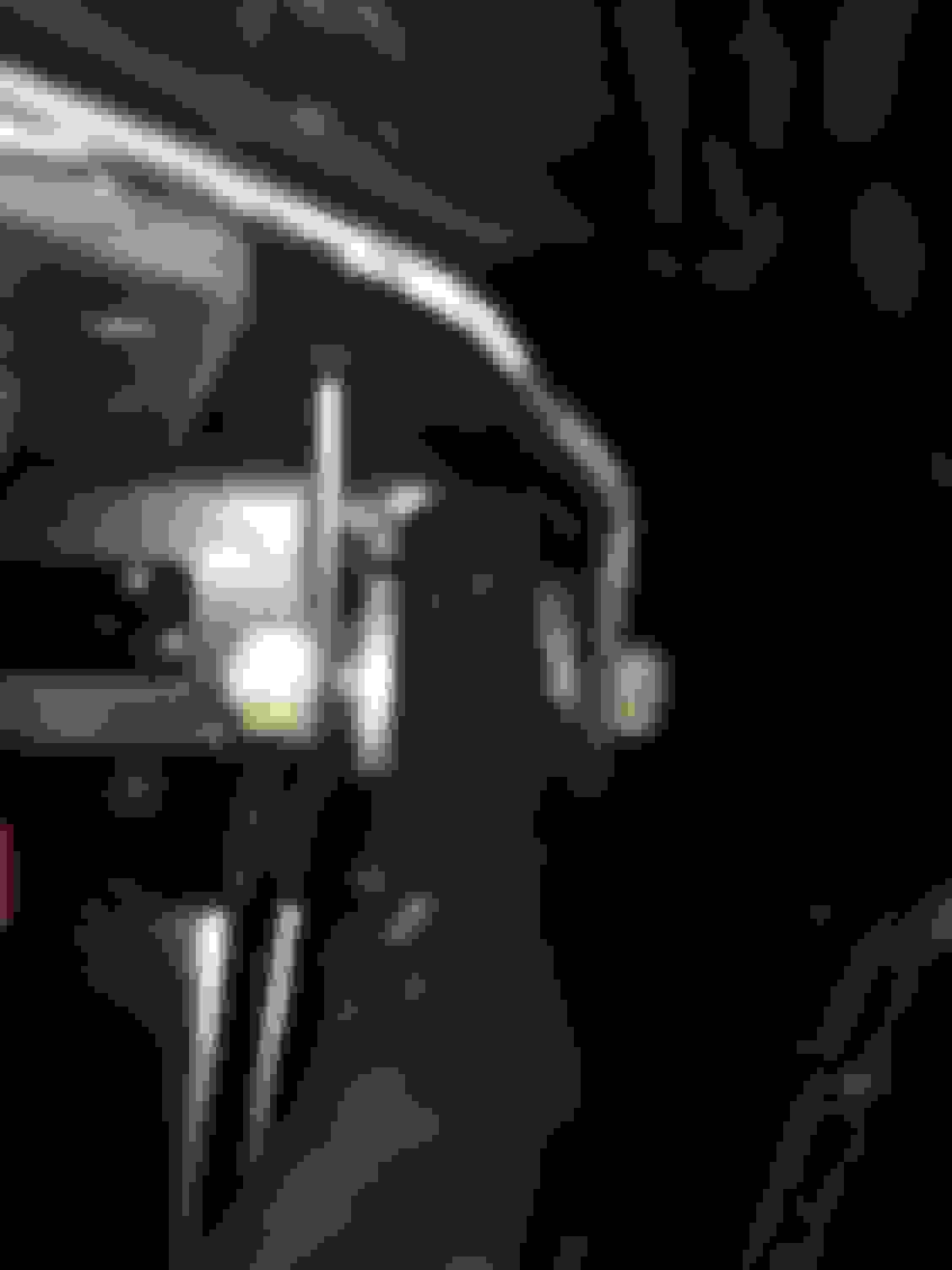
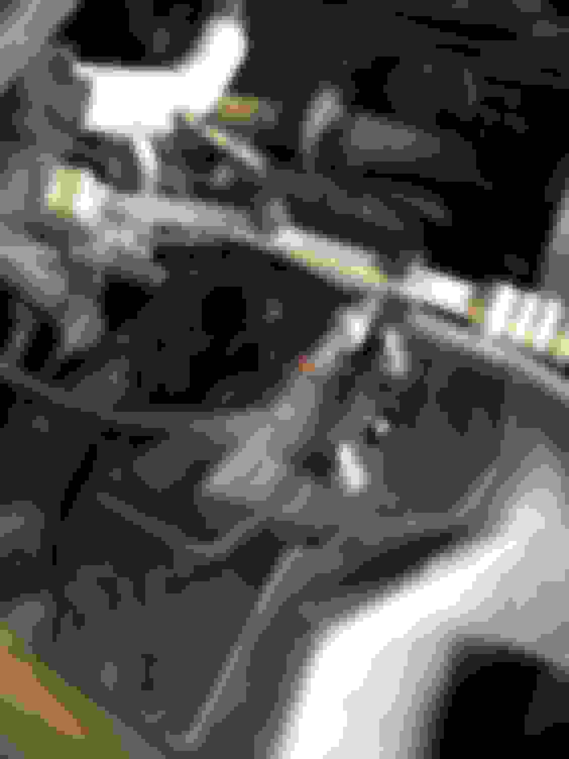
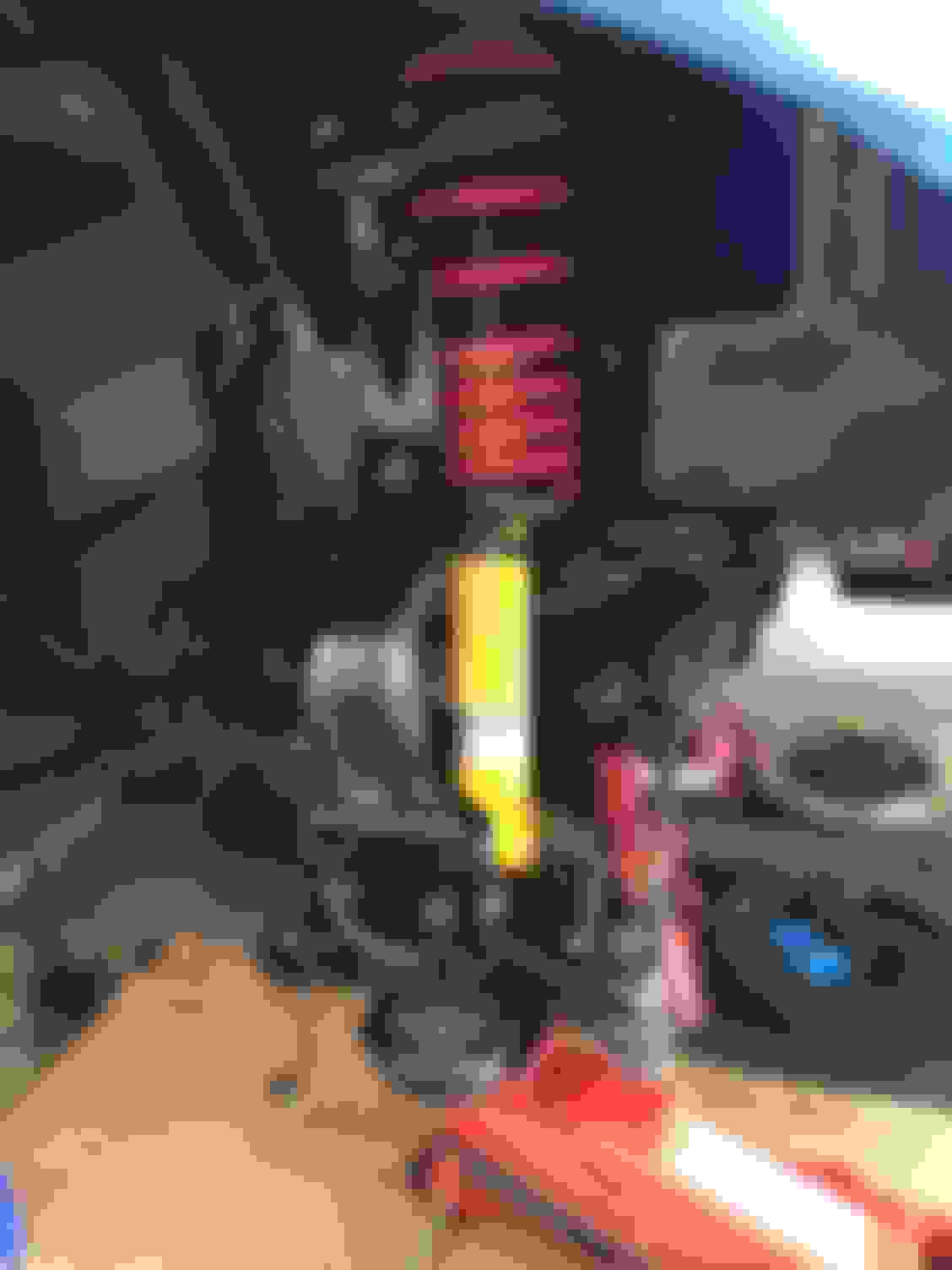
Also, you can look through one of the holes in the control to get a better look at how well the inside ball joint is seated. The picture kind of stinks but when you're there with a light you get a good view.
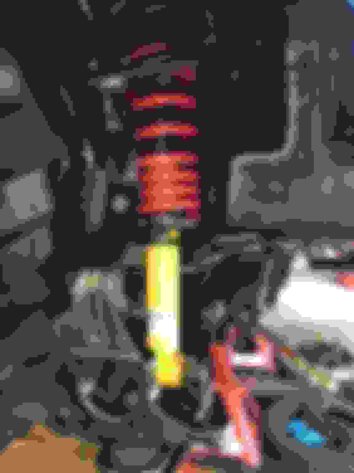
Make sure to watch the stud of the ball joint doesn't get caught on anything while being pressed.
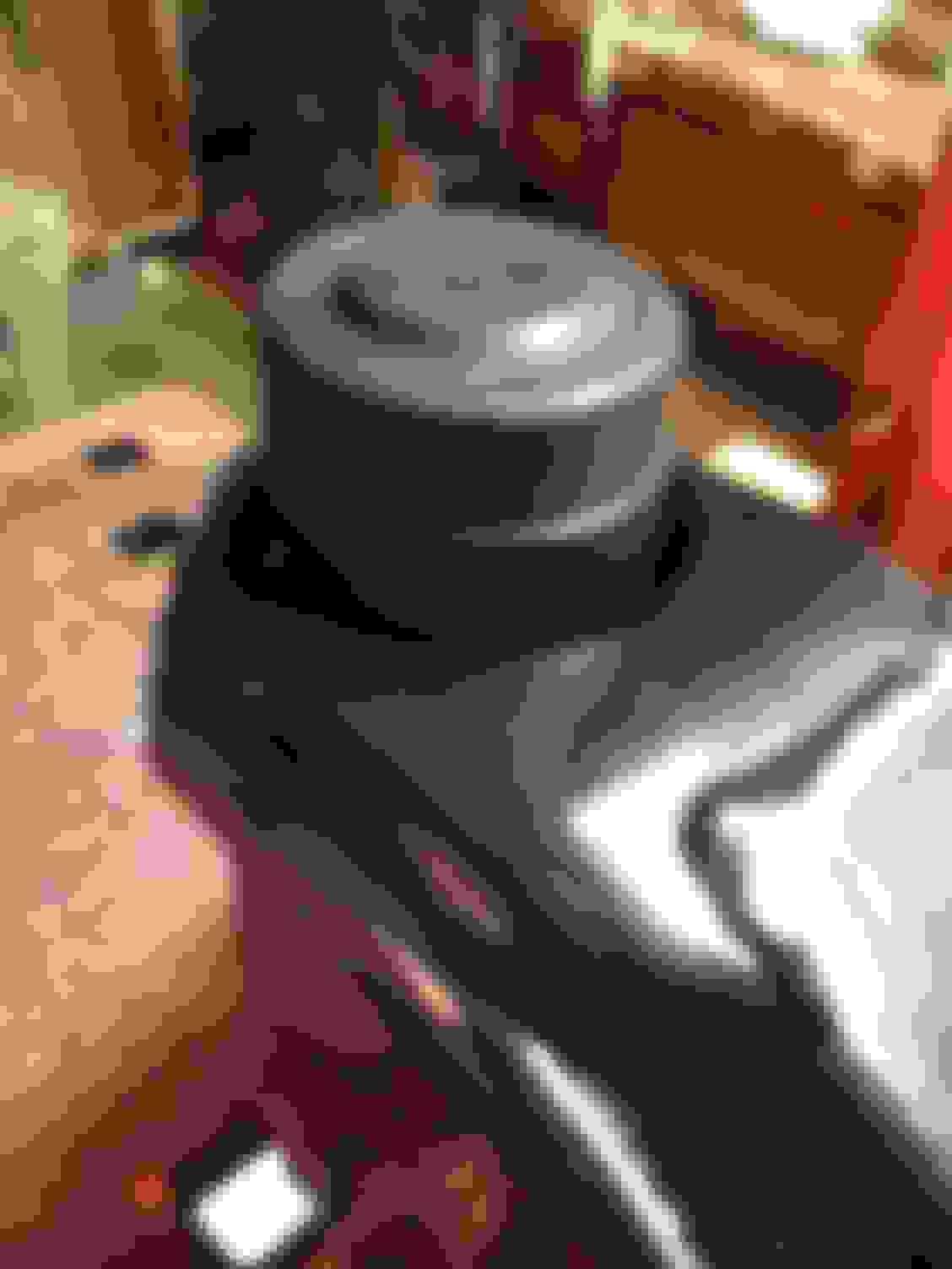
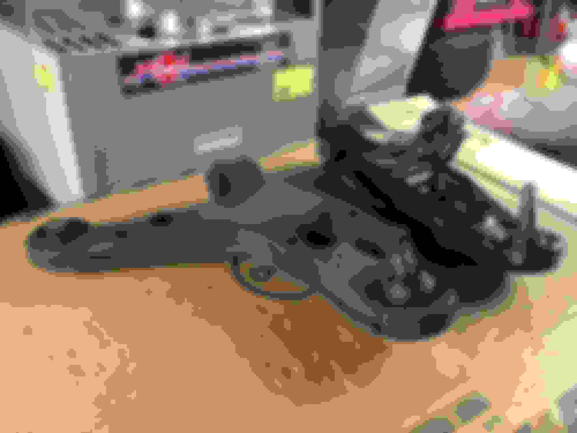
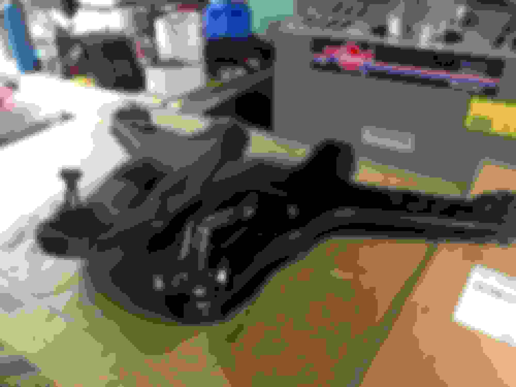
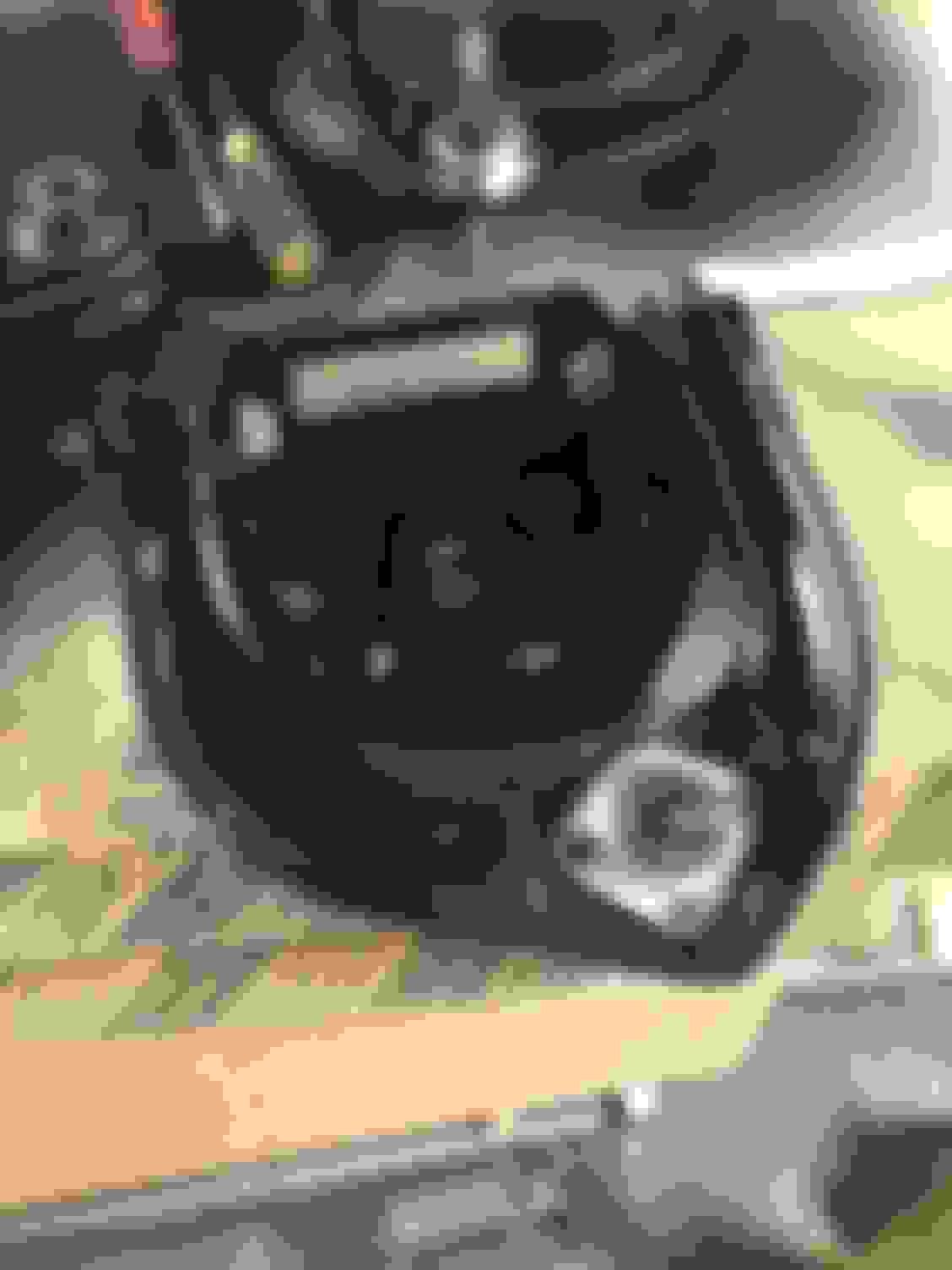
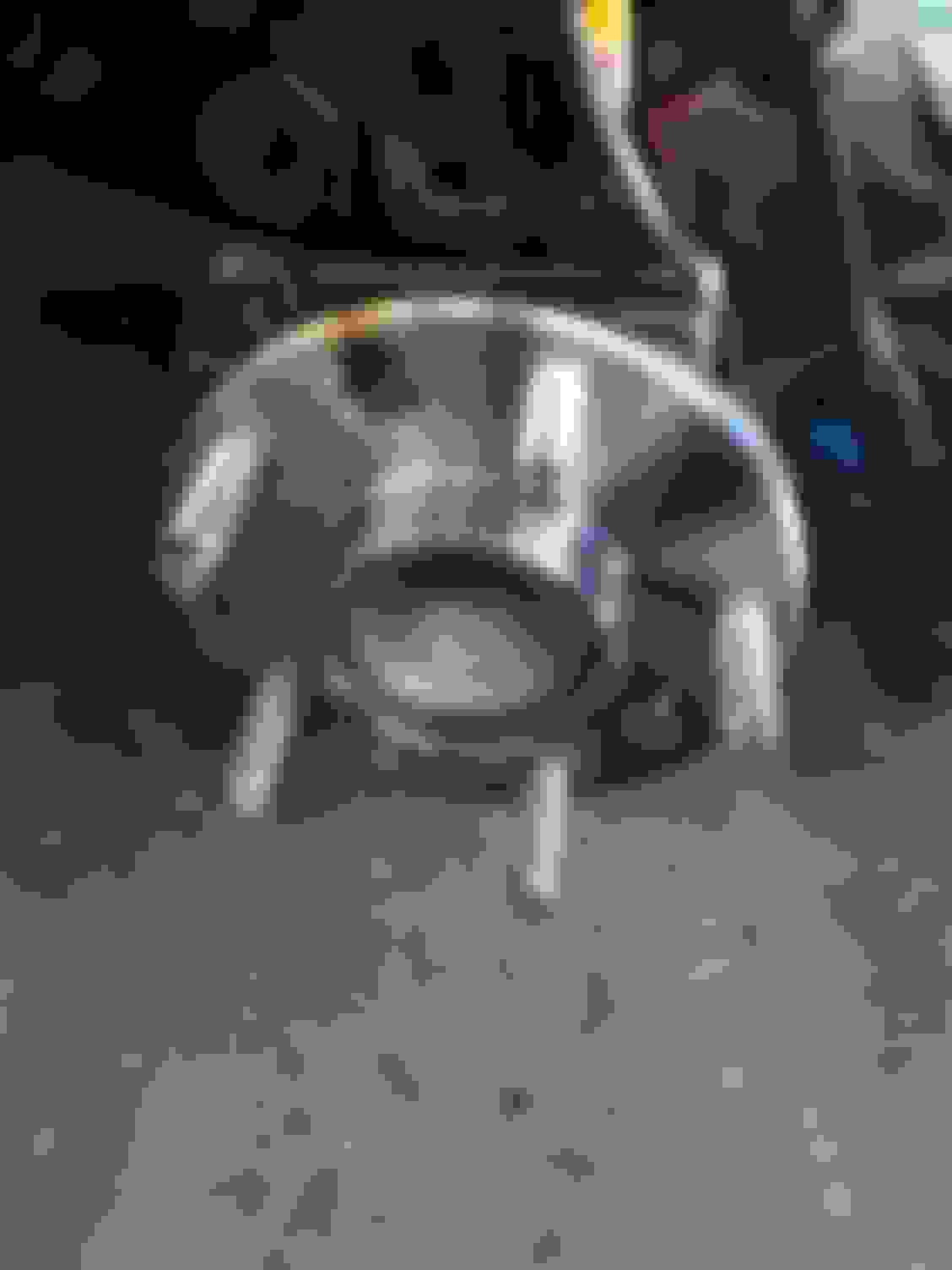
As you can see below, we did a good job of scuffing up the first arm. I don't care what paint you use, nothing was preventing this. There are a few small gouges on the sides, the photo actually looks a lot worse than it is. I'm going to touch these up before installation.
Here's the second arm that went a lot better after we made that jig, still a few scratches as to be expected but nothing major.
With the exception of touch up and installing the dust boot, the lowers are done and ready for installation.
And that's another episode of out with the old, in with the new.
On another update, I mentioned last week I had some extremely small rust spots coming through on my spindles and upper control arm mounts. My buddy said he though my coverage was poor so I put on a couple more coats of the VHT Roll Bar & Chassis paint on Friday, I took a look at them tonight when I got home and they're looking pretty good, no more small rust spots.
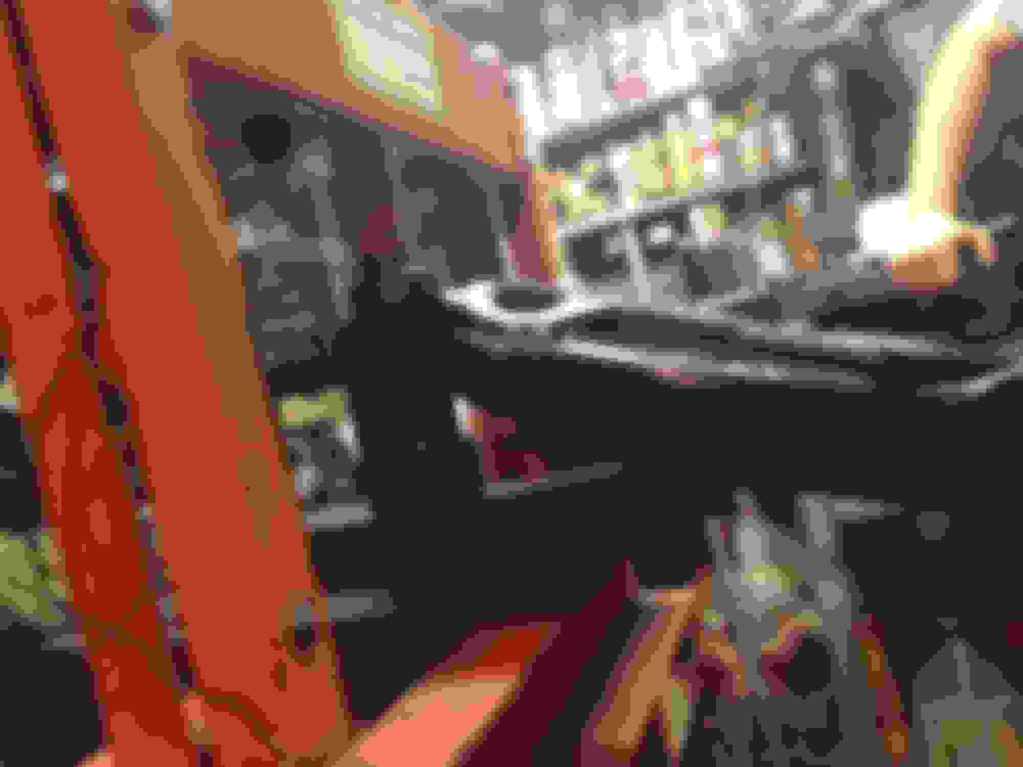
Also, just for some more F-body pic ****, after I was done pressing the ball joints in tonight, I helped a good friend of mine install an SS hood on his Z28. Enjoy!
Last edited by StoneColdLT1; 06-13-2017 at 11:17 PM.
I mean I did it without ruining the LCA, was it pretty? No. Will they still get scratched a little even with a shop? Probably, but they'll set up a jig and get it done in no time and most likely less damage than doing it yourself. Some people paint after everything is pressed in. The uppers were real easy but the lowers are hard to do without messing up the finish a little.
As for when they're seated it's pretty self explanatory when you see what there is, there is a grooved section of the ball joint that is what actually what fits and gets pressed in the control arm sleeve (Moog and some others have grooves, OEM and some other replacements don't). Above this grooved section is a larger lip, when this lip contacts the lip of the control arm that the grooved section gets pressed into, it's seated. Some times it's hard to tell, so we used a combination of a pick we used as a feeler, and the hole mentioned above to look in and see where the lip on the ball joint was in relation to the lip on the arm.
The vertical bushing doesn't get seated all the way, and the horizontal bushing, you need to look at what comes off your car and compare where the inner sleeves are to determine whether to leave a gap or seat all the way. But ball joints almost always get seated all the way, and make sure they are, there's a lot of force and pressure riding on these.
@ws6-speed: Just find a machine shop that does automotive parts (that's what most garages do anyway). They do this stuff all day long, so they can handle it.
@StoneColdLT1: If you had this to do over, do you think you might coat the A-arms after pressing in the bushings? Just curious. Don't forget to thread in the zerk fittings and grease the balljoints. Otherwise, looking better than new! Nice work!
@ws6-speed: The uppers are pretty easy to do and the rear LCA's look pretty easy to tackle with a store bought balljoint press, some hand tools, and some spacers. However, I can't see a shop charging you much to do the lowers if you don't feel confident or don't have access to the equipment and there would be nothing wrong with that. TBH, this was one heck of job, and my buddy and me, we're not professional mechanics but we're also no stranger to spinning wrenches either and have a good amount of resources. I sure wouldn't want to do it again, next time I need to do this, it's most likely going tubular.
eb110americana: That's a good question. Putting on three good coats of paint feels easier without everything installed IMO. Now all I have to do is tape a few areas and do a little touch up here and there which is no big deal to me. One plus of painting after besides avoiding damage from the press is you can hit the metal outer shells of the bushings for extra rust protection, but I'd still tape the rubber, balljoints obviously, and the poly caps on the problem solvers. I feel like it's easier to get a good solid three coats of paint the way I did it than taping all of that stuff and trying to prep and a get a good three coats of paint around it, but that's just my 2 cents, lots of guys press first then paint, it all comes down to personal preference. If you paint first, just be prepared for some touch up.
No, weather has been crap all weekend, haven't been able to get outside to get any work done.
As for your question about anti-seize, I'm really not sure. A quick google search or reading the back of the bottle would probably give you some insight into what you can and cannot use it on. I don't see why you'd really have an issue with some Permatex aluminum.
I can agree that your standard c-clamp kit will not get this job done. I used a small kit (harbor freight 10pc kit I think) for the sleeves and endcaps. Then I used a hydraulic shop press like the O.P. I had all the bushings and ball joints removed from the LCA s in a half hour and pretty much did it exactly like it's written in this thread.
Well, 2 days into it and the front end is finally done. More than 6 hours to remove and replace the bushings in the lower a arms! If anyone is wondering, a 2" black pipe works perfectly as a press guide for reinstalling the lower bushings. We had to cut it to 1" thick because none of the cups in the kit from autozone or oreilly's could fit in the c clamp to press the bushings in.
Also, I called 6 machine shops as well as hibdons tire and discount tire, both of which do front end work, and NO ONE would press out or in the bushings. Hibdons did do the ball joints for $140! It was a rip off but I didn't have any other choice. If you can't do this job yourself, there's no one else hat you can pay to do it for you.
A couple little learnings:
1) if you buy new upper a arms, they come with ball joints and hardware including bolts and nuts with lock washers. Don't fork them down to the specs listed in the chitons, you'll eat through the lock washer. I know better than to torn a lock washer but it was 10:30 at night and I was tired.
The energy sway bar bushings also come with washers, don't use them. The drivers side bushing has a plate that attaches to the bushing bolt. If you use washers on the bushing, the plate doesn't line up any more. Also, the stock bolts have nuts with built in washers.
Mark your lower a arm connection bolts with a paint pen. A quick mark around the bolt and you can easily reposition them when reinstalling to get damn near perfect alignment. Do the same with the tie rod ends.
I can't stand it when machine shops turn down work, I've had multiple shops turn down small jobs I needed done, guess what, they're not getting my business when I need my 383 done (which I'm sure they would take in a heartbeat if I called). Luckily I found a guy local to me that did some work on my buddies Olds 403, if he can physically do the work, he'll take it, and he's good too. He's the one who bored my rotors for this job.
Between some family events this past weekend and basically running my department at work by myself this week, I've been pretty busy, but I have gotten around to touching up some paint and making some custom brake like adapters needed to make the LT1 hard lines work with the custom hoses. If I don't get caught up late at work today and make it home at a reasonable time, I'll cut and flare the lines on the car and post up some pics of all the little bits of work I got done last week. Long weekend coming so as long as the weather isn't bad, car should be on the ground.
I was a bit surprised by the apparent lack of lowering from the BMR spring/Koni orange shock combo up front. I have 27" from ground to fender lip. Seems a bit high to me.
Earlier last week, I gravity bled the front brake system completely to get some fresh DOT4 fluid in there. I'll do the rear when I'm back there. To be honest, I could have done this when I modified the hard lines today but I wasn't sure what I was doing with them at the time.
I ended up picking up some StopTech Racing STR 600 DOT4 brake fluid from a local performance shop. The dry and wet boiling temps for this fluid are very similar to Motul RBF 600 so it should hold up well at the track.
Next, I siphoned as much old fluid out of the master as I could and refilled it with new. The front chamber of the master is for the rear brakes and the rear is for the front.
Then just crack the bleeders and let it drain. Make sure not to let the master run dry, and keep an eye on it because it will go faster than you think.
I had the calipers sitting on the ground, a clear plastic cup hung nicely from the bleeder and allowed me to see when clean fluid was coming through.
Now for the brake lines, I'm not completely sure, but I believe on LS1 cars, the hard line turns a 90 and all you need to do is remove the old hose and bracket and install your custom hose and bracket from Kore3.
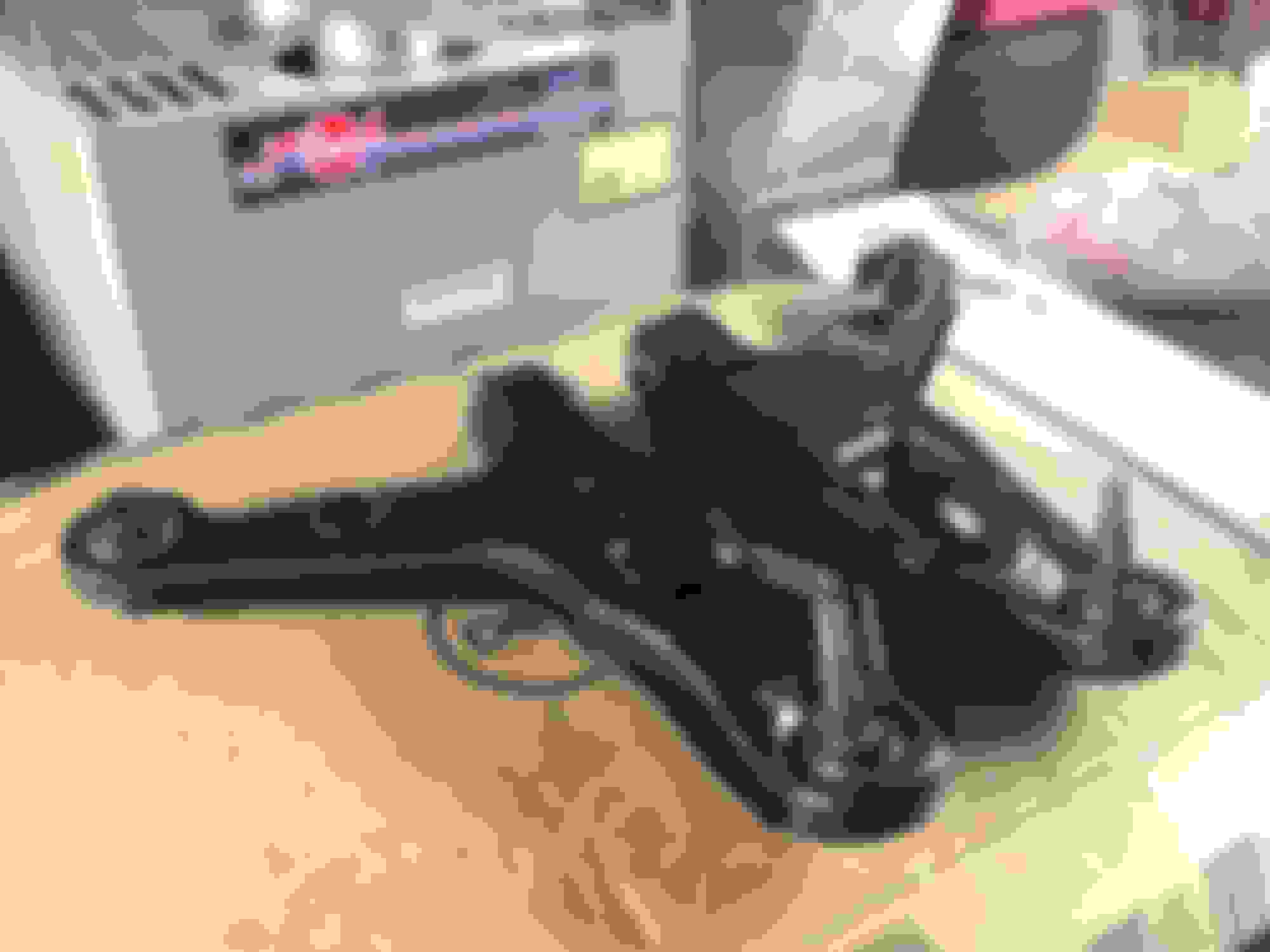
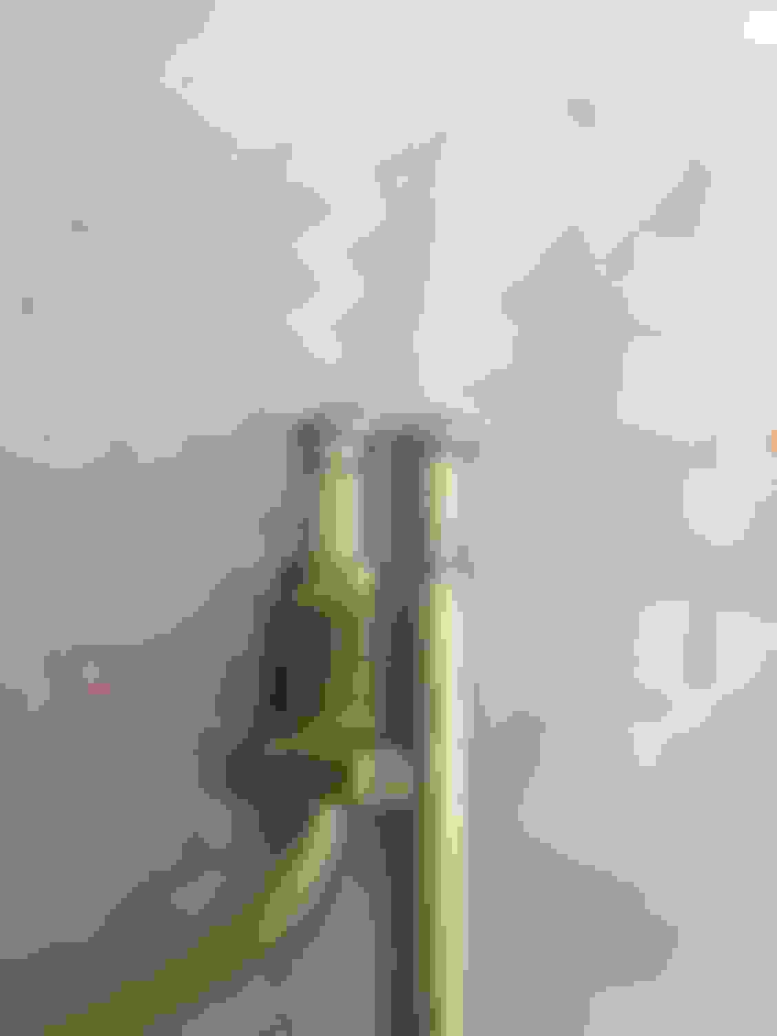
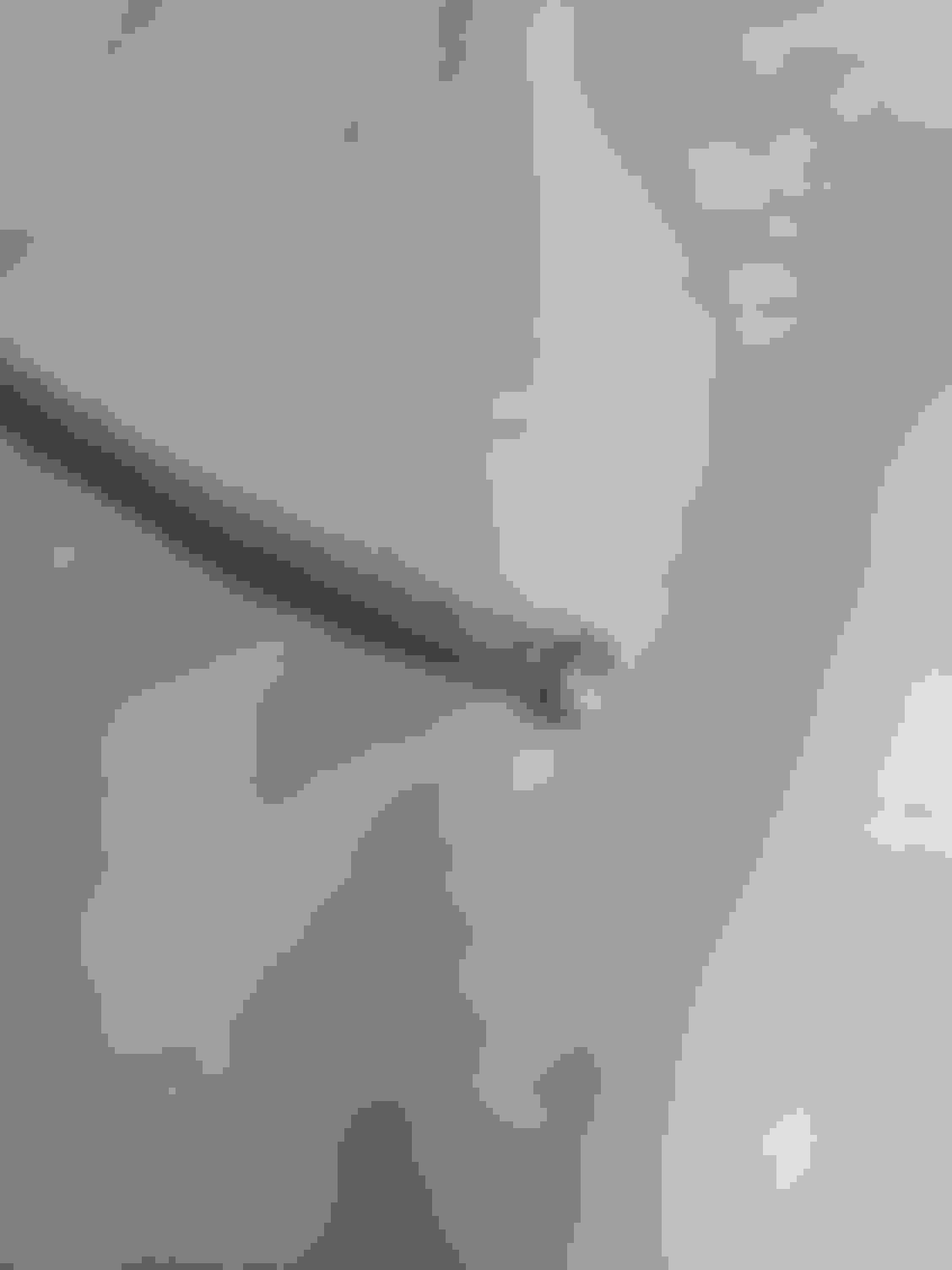
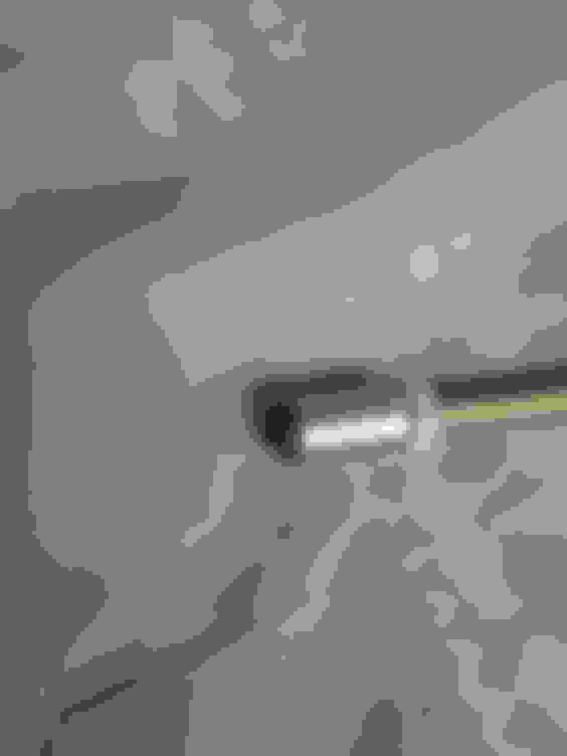
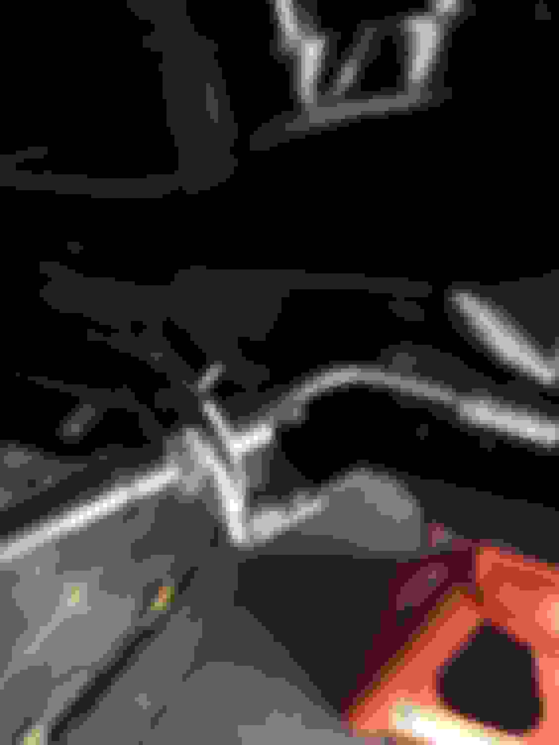
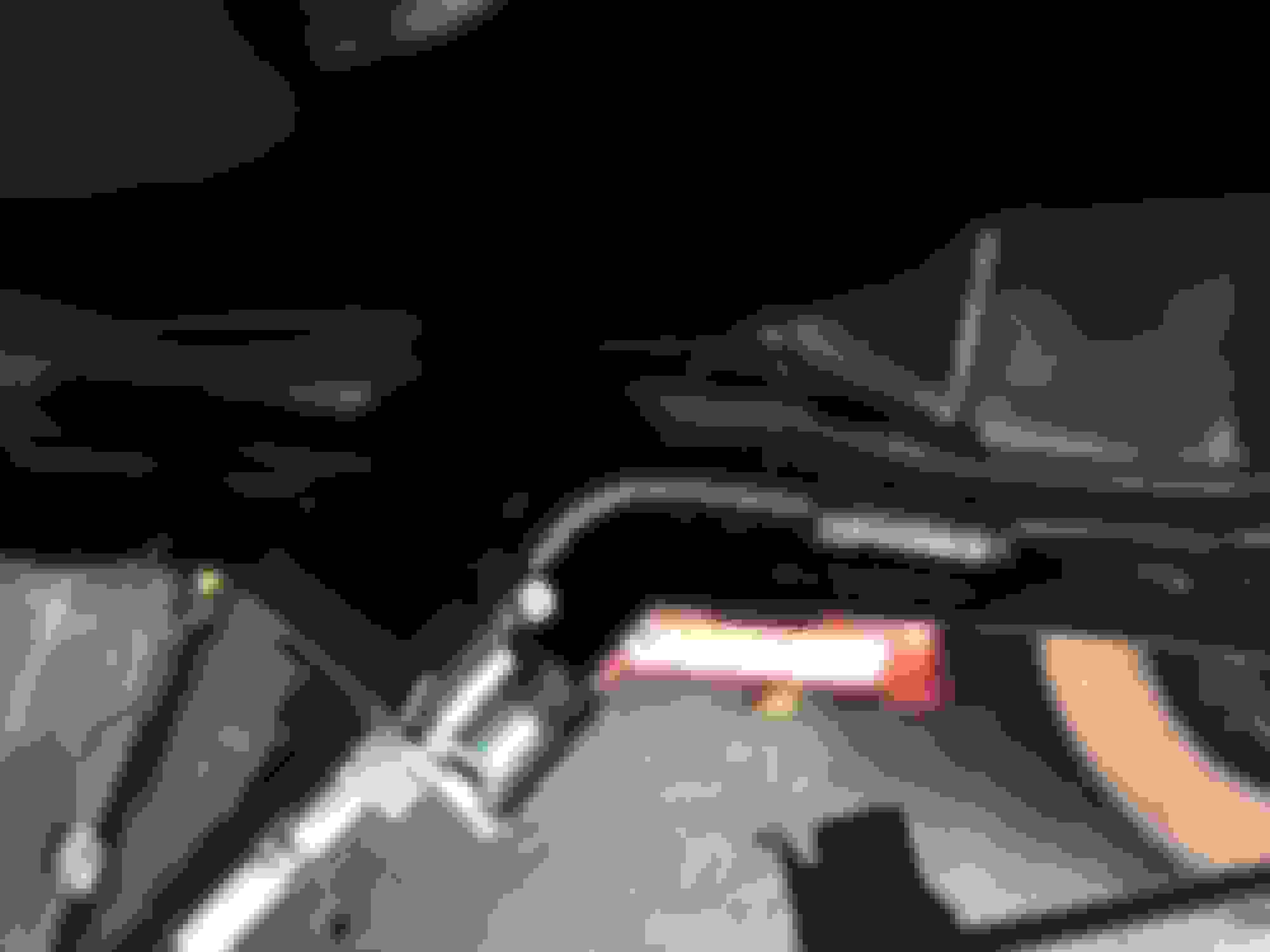
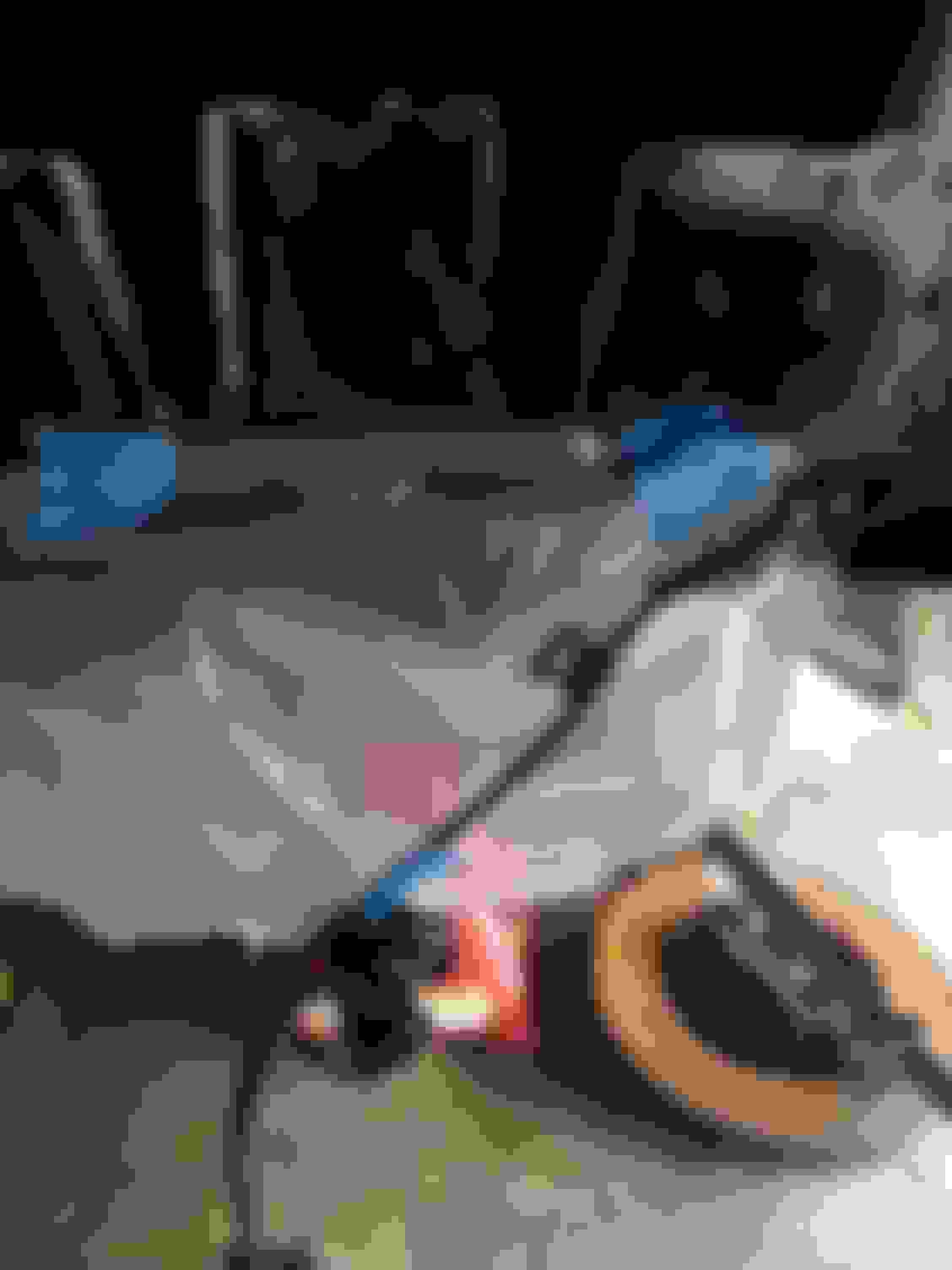
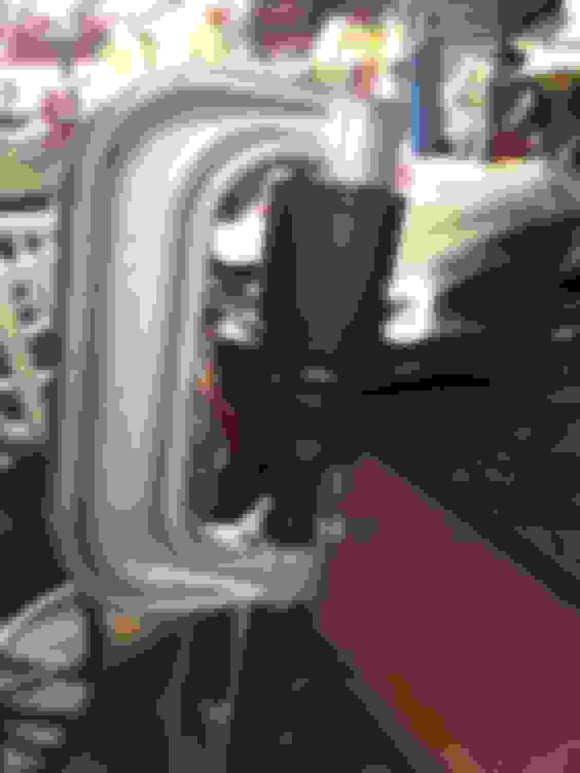
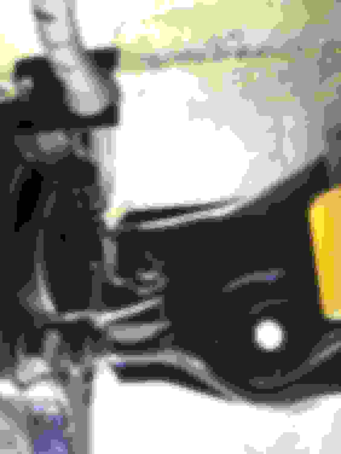
However, if you're a glutton for punishment and Optisparks like I am, some modification to the hard line will be necessary. Stock, your LT1 line should look something like this.
It goes left, down, back, and all over the place until it comes back up and the hose comes out upward. This is an issue as the custom lines come with new brackets and the hoses need to come out facing the caliper and not up like the LT1 lines.
There are a few ways to fix this. Quickest would be to just bend the line back around to where you need it, however, I thought this would look like crap and bending a 23 year old brake line like that might cause it to crack. So I decided to cut and flare the original line and fab a new adapter line to get the rest of the line properly to the hose.
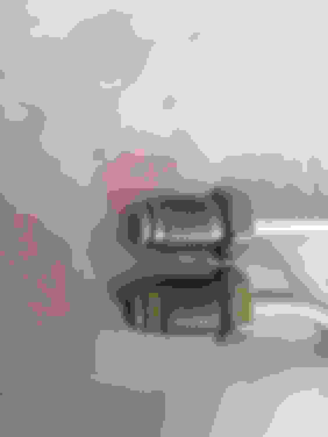
I first started by creating the adapter lines. It's going to be a 3/16" tube size and the fitting that goes into the custom hose will be an M10x1.0 bubble. I used a 3/8-24 inverted fitting with a union for where the adapter will connect to the original hard line.
I first started by doing the bubble end. I did it by using the flat portion of an inverted/double flare tool vice.
Notice in relation to a 3/16" size die how far I had the tube end stick above the vice. Then put the die in the tube, mock up and crank down on the press and you should be done.
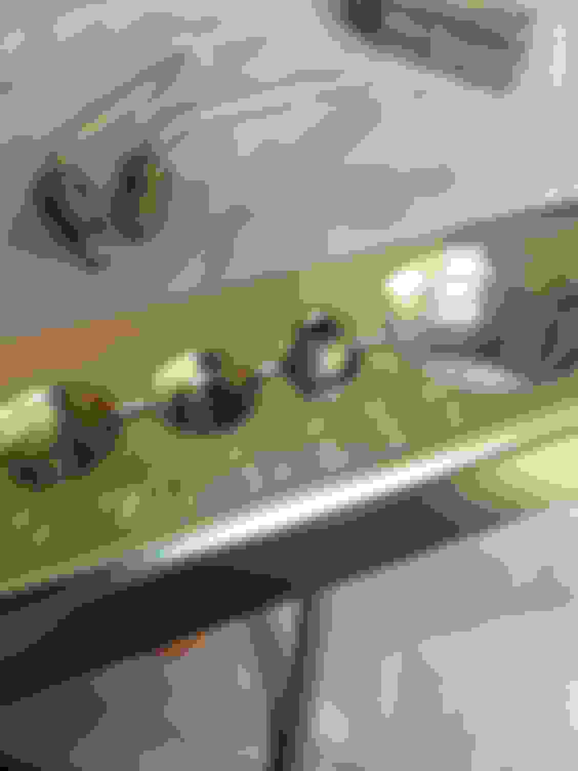
Luckily, I had a perfect bubble flare that came pre-made on the line from the manufacture that I could use to compare mine to. Mine is on the right and is the one without the bend. These usually crush down once they're tightened so it doesn't need to be flawless, but I did do a couple rounds of testing how far the tube needs to protrude from the vice, and if it came out a little off, I re-did it until I got to this one.
I then tried to bend the lines to a 90, but they're a little closer to a 45 to avoid pinching them, and then I put an inverted flare on the other end.
To do the inverted flare, use the beveled end of the vice. Note in relation to the die how much the end of the tube protrudes past the vice. Put the die in the tube, mock up and crank down on the press, loosen, remove the die from the line, crank down on the press again and you're done.
Now that my adapter lines are complete, I mocked up the hoses, brackets and adapter lines to mark where to cut the hard line on the car, leaving plenty extra for mess-ups and re-dos, luckily I didn't have any.
I then taped up a piece of plastic to keep brake fluid off my fresh paint.
When cutting the line with that stupid coil on it, it always comes out with a bur on it. So I do a crappy cut, spin the coil off a good amount of the line, cut the coil and then do a nice clean cut for the flare. Don't forget to put the nut on before you flare and do as above.
I then put on a union and cap to keep the fluid from draining until I'm ready to install the calipers, hoses, and adapter lines. I even bolted up he master to test them under pressure. The pedal is rock hard and doesn't bleed off which is good. Now if I have an issue later, I know it'll be with the adapter line flares and not with these.
Now we have an LT1 car ready for some CTS-V, LS1, or Corvette brakes.
Last edited by StoneColdLT1; 06-29-2017 at 07:56 AM.
Some other updates from the past week. I got around to doing some paint touch up on the inner fenders and other small areas, however, I think most would like to see the lower arms that have been cleaned up since being severely scratched from pressing the ball joints in.
Here are some before and after photos.
I had some people ask me which would be easier, to paint first, then press, or to press, then tape and paint. I have to say the way I did it I think is much easier. It was just time consuming and a pain to tape those ball joints, and that was all I taped because that was the only area that needed touch up. If I had to do that for every bushing it would have been a real pain.
I think it is much easier to paint first and touch up what you need later.
Managed to get out this holiday weekend in the 100 degree heat and get some work done on the car.
Parts you'll need
Assembled Lower Control Arms
Assembled Upper Control Arms and Mounts
Assembled Spring/Shock Assembly Moog Tie Rod End, Inner - EV260
Moog Hub Assembly - 513090
Before I started, I had to put the dust boot on the lower control arms. I actually had to use a press to get them on as doing it by hand, one side would pop off when you got the other on. Didn't need to get a wrench on the press and kill it, just hand tight to set it down.
Next it was time to start putting stuff on the car, first is the lower control arms. I covered the bolts in anti-seize in avoid future corrosion. The Moog problem solver vertical bushing makes it much easier as you can line it up with a screw driver.
I installed the nuts but didn't tighten. All bushings should be torqued with the vehicles weight on them.
Once the lower arm is installed, it's time to get the shock/spring assembly, and the upper mount and control arms ready for installation.
I installed the nuts and bolts that connect the upper control arm to the upper mount but didn't tighten completely. Now you're supposed to torque the bushings down with the vehicles weight on them, the issue with the upper arms is one of the bolts and nuts is impossible to access on the car. So what I did was I installed the shock/spring/upper arm, jacked up the lower control arm so that half of the vehicle is supported by it, mocked up the spindle, and tighten one side of the upper control arm so it holds it in place. I then take it all apart and torque the upper control arm nuts/bolts on the bench to 72 ft-lbs and you'll have your upper control arm torqued in the ride height position.
Before I reinstalled, I covered the top of the shock, the bottom and top of the mount and the underside of the shock tower with anti-seize.
Notes to remember when installing the spring/shock assembly, the bolts that connect the lower shock to the control arm come in from the bottom and didn't go all the way through the shock mount with the front arm extended. I needed to jack up the front lower arm for the bolts to slide through. Install the nut and torque to 48 ft-lbs.
Moving around to the top, you can reuse your old bolts and nuts, however, my spring mounts and isolator both came with new bolts and nuts so I decided to use those. The new bolts didn't seem to have the same size flange around the head as the old ones, so I ran to Home Depot and got some graded washers to put in with them.
These definably went easier than they came out. Torque the nuts to 32 ft-lbs and the bolts to 37 ft-lbs. I think I may have slightly stripped one of the bolts on the drivers side as it felt like it was starting to give way while being torqued. I may pick up a graded nut from Home Depot to put on the bottom from the wheel well side to be safe.
Don't forget, once the driver side is torqued down, reinstall the master cylinder bolts and tighten down.
Once the shock/spring assembly is in and the lower arm is supporting the weight of the car, I went ahead and torqued the lower arm down as well. I'm going to get an alignment once the springs settle, but it's going to be aggressive so I decided to pull the arm out as far as it'll go. Torque the front horizontal bushing to 74 ft-lbs and the rear vertical bushing to 85 ft-lbs.
After that, it's time to install the spindle. Get it seated fully on the lower and upper ball joint. Install the castle nuts. I torque the bottom one first to 81 ft-lbs, then the upper to 39 ft-lbs. Install the cotter pins and zerk fittings.
Next was the tie-rod end. It was the last part I wanted to torqued down while I had the weight of the car supported on the jack. Note that the ball joints and tie-rod end don't need to be tightened down at ride height as long as they're seated properly on the ball studs, but I did it because I already had the front lower arm supported so it couldn't hurt.
Even though I'm going to get an alignment, I counted how many rotations my old tie rods took to remove and I installed these with the same amount of rotations on each side so my toe won't be completely off. Torque the castle nut to 35 ft-lbs and install the cotter pin and zerk fittings. Don't forget to tighten up the jam nut.
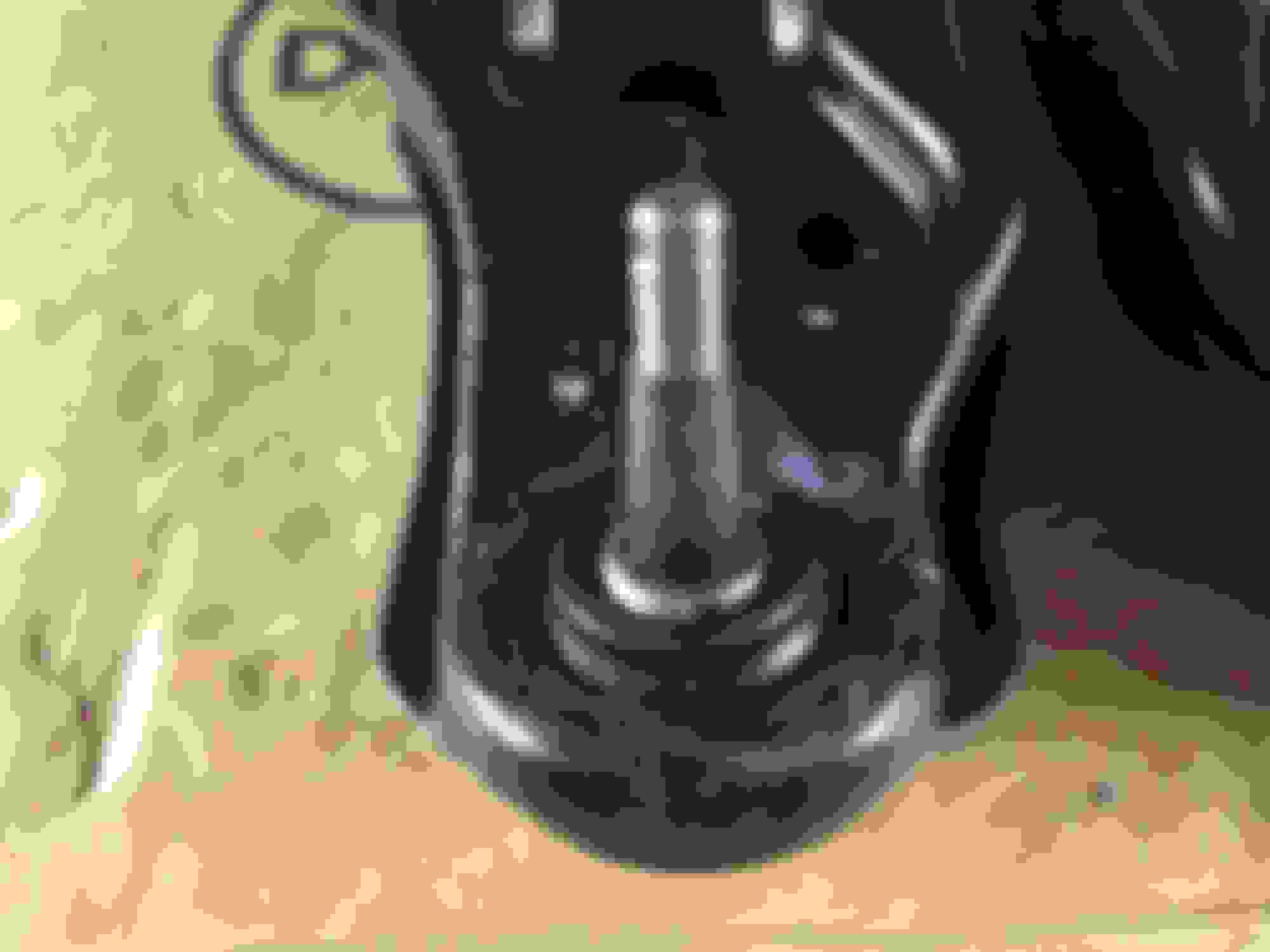
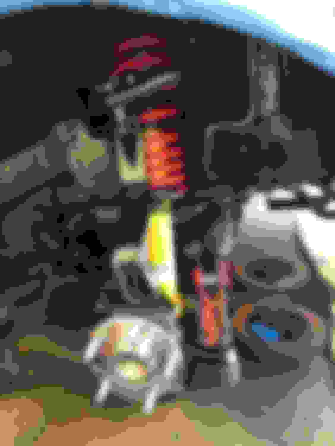
Once that was done, I decided to install the hubs. Note that on the Moog hubs, the connector for the ABS sensor faces forward so that the side that plugs in faces the rear. My hubs didn't have a note or instructions, but I noticed it on a stock photo shown below. It's also the way the OEM hubs are.
The litttle bracket that holds the ABS line goes on the upper most rearward bolt. Torque these to 63 ft-lbs.
Still have brakes, sway bar, and all the little stuff to do. I would have had the sway bar on today, however, like an idiot I started to cross thread one of the bolts. I got a tap and die to try and clean up the bolt and hole, I may also pick up a graded nut to put on top of the mount for extra security.
Hopefully I won't get caught at work tomorrow and I can keep the progress going.
Last edited by StoneColdLT1; 07-05-2017 at 07:24 AM.
 06-12-2017, 08:56 AM