Ya think I'm gonna buy a head unit when I did this?


 08-13-2011, 11:57 AM
#25
If you don't want to do the work or are not handy with a soldering iron, I'd recommend sending your radio to a place like Replacement Radios. (There are several outfits that do the same work.) They can replace the bulbs for you. BTW - I'd highly recommend you send your unit to be rebuilt vs. purchasing another used unit. The catch is that you have to pay for shipping, the service, etc.
If you have basic soldering iron skills, its no big deal to do the incandescent replacement. Not counting the time it takes to disassemble the radio and heat up a soldering iron, it takes 5 minutes.
08-13-2011, 01:28 PM
#26
Teching In
-Can anyone comment on what bulb that is? Or what could be used to replace it in the Monsoon head? (CD version, as shown in the thread). The standard one is a twistlock pcb bulb thats soldered in place, with no markings. I can't find an exactly similar one online. I would <guess> that a suitable wire-ended 14v could be used? I don't really want to use a LED because the light distribution may be crap...
Thanks,
D.
Thanks,
D.
08-16-2011, 07:21 PM
#27
-Can anyone comment on what bulb that is? Or what could be used to replace it in the Monsoon head? (CD version, as shown in the thread). The standard one is a twistlock pcb bulb thats soldered in place, with no markings. I can't find an exactly similar one online. I would <guess> that a suitable wire-ended 14v could be used? I don't really want to use a LED because the light distribution may be crap...
Thanks,
D.
Thanks,
D.
 08-26-2011, 09:34 PM
#29
Staging Lane
Join Date: Apr 2008
Location: New York
Posts: 69
Likes: 0
Received 0 Likes
on
0 Posts

My problem is I cant find the 680 Ω, � watt resistors. Also with the soldering Iron can I use the old school soldering i slow, because someone said it takes too long and will break the LED.
Also how do I know which side of the LED gets the resistor?
08-26-2011, 10:54 PM
#30
Copy & Paste Moderator
I thought Radio Shack had 680 ohm 1/4 watt resistors in the store? Are there any other electronics parts/hobby stores near you? If not, you can order from Digikey, Mouser, or possibly DealExtreme.
What do you mean by "old school soldering"? I just use a regular 35watt Weller soldering iron and rosin-core solder. I bought the iron at You-Do-It Electronics (local electronics parts/hobby store) and the solder at RadioShack (0.032 diameter, 60/40 blend). Just let the iron heat up at least a few minutes before you try using it. I typically plug it in and let it heat up while I assemble the items I need and prep.
Just a reminder, heat up the part (metal leg or wire) and touch the solder to that. Solder will flow towards heat. It also helps to pre-tin the soldering iron tip and the wire to make the bond happen faster and stronger. Watch some soldering iron tips on YouTube to see what I mean and for more tips and tricks.
Put the resistor on the positive leg of the LED.
The soldering iron I use looks like this:

(Image from Amazon)
I rest it in a stand that looks like this:

(Image from Amazon)
The moistened sponge is to wipe the soldering iron tip. Sometimes stuff you don't want gets built up on the tip or there is extra solder so a quick wipe on the sponge cleans the tip. Then you can re-tin the tip and get back to work. Just make sure to remember to moisten the sponge before you start working or you'll burn the sponge when you try to use it.
A "helping hand" is also quite useful to hold things while you work. Here is an example:

(Image from Amazon)
I usually have the alligator clip on the "helping hand" hold a regular spring-loaded clothes pin and have the clothes pin hold onto the part or wire I'm working with. Its gentler on the wire/part (less chance of puncture/scratch/etc). A clothes pin also won't hold as firmly, so that is a double-edged sword so-to-speak.

(Image from Amazon)
I think Harbor Freight might also have some soldering supplies. I was disappointed in the last one I looked though. If there is a Fry's near you, they should have all the stuff you need.
I make no claim to being an expert. I just have some experience making and repairing simple things.
What do you mean by "old school soldering"? I just use a regular 35watt Weller soldering iron and rosin-core solder. I bought the iron at You-Do-It Electronics (local electronics parts/hobby store) and the solder at RadioShack (0.032 diameter, 60/40 blend). Just let the iron heat up at least a few minutes before you try using it. I typically plug it in and let it heat up while I assemble the items I need and prep.
Just a reminder, heat up the part (metal leg or wire) and touch the solder to that. Solder will flow towards heat. It also helps to pre-tin the soldering iron tip and the wire to make the bond happen faster and stronger. Watch some soldering iron tips on YouTube to see what I mean and for more tips and tricks.
Put the resistor on the positive leg of the LED.
The soldering iron I use looks like this:
(Image from Amazon)
I rest it in a stand that looks like this:
(Image from Amazon)
The moistened sponge is to wipe the soldering iron tip. Sometimes stuff you don't want gets built up on the tip or there is extra solder so a quick wipe on the sponge cleans the tip. Then you can re-tin the tip and get back to work. Just make sure to remember to moisten the sponge before you start working or you'll burn the sponge when you try to use it.
A "helping hand" is also quite useful to hold things while you work. Here is an example:
(Image from Amazon)
I usually have the alligator clip on the "helping hand" hold a regular spring-loaded clothes pin and have the clothes pin hold onto the part or wire I'm working with. Its gentler on the wire/part (less chance of puncture/scratch/etc). A clothes pin also won't hold as firmly, so that is a double-edged sword so-to-speak.
(Image from Amazon)
I think Harbor Freight might also have some soldering supplies. I was disappointed in the last one I looked though. If there is a Fry's near you, they should have all the stuff you need.
I make no claim to being an expert. I just have some experience making and repairing simple things.
Last edited by VIP1; 08-26-2011 at 11:25 PM.
08-26-2011, 11:29 PM
#31
Staging Lane
Join Date: Apr 2008
Location: New York
Posts: 69
Likes: 0
Received 0 Likes
on
0 Posts
Wow that was very helpful!!
There are not many electronic stores nearby, but I will look for one. My soldering Iron looks like the one you have, the one my friend said to use looks like a drill with a soldering tip on the end.
Thanks for all the help, I hope to have this done soon!!!
There are not many electronic stores nearby, but I will look for one. My soldering Iron looks like the one you have, the one my friend said to use looks like a drill with a soldering tip on the end.
Thanks for all the help, I hope to have this done soon!!!
08-26-2011, 11:35 PM
#32
Copy & Paste Moderator
That other soldering iron your friend is talking about is a "soldering gun" and looks like this, right?

(Image from Amazon).
I would not use that for soldering small LEDs on a circuit board. Its too powerful and the tip is too large. A regular 35 watt soldering iron is plenty for LEDs and circuit boards.
If you have an old/weak soldering iron, you might want to get a new one, but you don't need a "gun" for this project. I've found that the 35 watt Weller that I have has worked well for every project I've used it on. I've soldered 12 gauge speaker wire to speaker terminals, soldered connectors to controllers, repaired broken headphones, built lightsabers, soldered 14 gauge 4-core wire for my headlight relay harness, re-wired outputs on old game consoles (to bypass proprietary connector and give additional outputs like RGB), etc. It has always done the job.
Every connection / terminal / pin I assembled in this pic was soldered using a 35watt Weller soldering iron:
(terminals & pins are crimped, soldered, and wrapped in heatshrink)
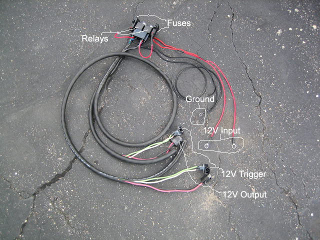
(pic of the relay harness I built for my Hella 90mm projector install)
(Image from Amazon).
I would not use that for soldering small LEDs on a circuit board. Its too powerful and the tip is too large. A regular 35 watt soldering iron is plenty for LEDs and circuit boards.
If you have an old/weak soldering iron, you might want to get a new one, but you don't need a "gun" for this project. I've found that the 35 watt Weller that I have has worked well for every project I've used it on. I've soldered 12 gauge speaker wire to speaker terminals, soldered connectors to controllers, repaired broken headphones, built lightsabers, soldered 14 gauge 4-core wire for my headlight relay harness, re-wired outputs on old game consoles (to bypass proprietary connector and give additional outputs like RGB), etc. It has always done the job.
Every connection / terminal / pin I assembled in this pic was soldered using a 35watt Weller soldering iron:
(terminals & pins are crimped, soldered, and wrapped in heatshrink)
(pic of the relay harness I built for my Hella 90mm projector install)
Last edited by VIP1; 08-26-2011 at 11:57 PM.
08-27-2011, 12:10 PM
#33
Staging Lane
Join Date: Apr 2008
Location: New York
Posts: 69
Likes: 0
Received 0 Likes
on
0 Posts
That wiring harness looks professional!
Okay so I found a radioshack they had 680 ohm 1/2 watt resistors not 1/4 watt. Does that make a difference? Or should I return them?
Okay so I found a radioshack they had 680 ohm 1/2 watt resistors not 1/4 watt. Does that make a difference? Or should I return them?
08-27-2011, 12:30 PM
#34
Copy & Paste Moderator
1/2 watt just means its physically larger and can handle a greater load (more power). It should be fine for your application as long as it fits where you are putting it.
08-27-2011, 01:02 PM
#35
Staging Lane
Join Date: Apr 2008
Location: New York
Posts: 69
Likes: 0
Received 0 Likes
on
0 Posts
09-05-2011, 03:06 PM
#36
Staging Lane
Join Date: Apr 2008
Location: New York
Posts: 69
Likes: 0
Received 0 Likes
on
0 Posts
So I did the gauges and all the interior LED swap................then today I went to do the radio, I looked at the photo of the finished one in the write up to know which side the resistor goes in the circuit board, well the first one I did only worked in reverse, I went to do the second one and no all the dash lights stopped working....I dont know what to do. I saw a bit o smoke.
09-05-2011, 04:44 PM
#37
Copy & Paste Moderator
How / Where were you doing this? Hopefully not while still installed in the car with power.
Best way to do this is to remove the part from the car and work at a table without any power going to the parts you are working on.
Where was the smoke? Inspect the area carefully for anything that looks like it may have burnt or melted.
However, the dash lights not working may be as simple as a fuse. Check the TAIL LPS and the IP DIMMER fuses. One of them may have blown. Don't just visually inspect them. Remove the fuse from the car. Set the multimeter to the "beep" setting. Touch one electrode to one tab of the fuse and touch the other electrode to the other tab of the fuse. If you hear a beep, the fuse is good. If you don't hear a beep the fuse is bad. You could also use the OHM setting instead of the BEEP setting, but you'll have to look at the multimeter to see the amount of resistance in the fuse. There should be no resistance.
09-05-2011, 07:39 PM
#39
Staging Lane
Join Date: Apr 2008
Location: New York
Posts: 69
Likes: 0
Received 0 Likes
on
0 Posts
How / Where were you doing this? Hopefully not while still installed in the car with power.
Best way to do this is to remove the part from the car and work at a table without any power going to the parts you are working on.
Where was the smoke? Inspect the area carefully for anything that looks like it may have burnt or melted.
However, the dash lights not working may be as simple as a fuse. Check the TAIL LPS and the IP DIMMER fuses. One of them may have blown. Don't just visually inspect them. Remove the fuse from the car. Set the multimeter to the "beep" setting. Touch one electrode to one tab of the fuse and touch the other electrode to the other tab of the fuse. If you hear a beep, the fuse is good. If you don't hear a beep the fuse is bad. You could also use the OHM setting instead of the BEEP setting, but you'll have to look at the multimeter to see the amount of resistance in the fuse. There should be no resistance.
Best way to do this is to remove the part from the car and work at a table without any power going to the parts you are working on.
Where was the smoke? Inspect the area carefully for anything that looks like it may have burnt or melted.
However, the dash lights not working may be as simple as a fuse. Check the TAIL LPS and the IP DIMMER fuses. One of them may have blown. Don't just visually inspect them. Remove the fuse from the car. Set the multimeter to the "beep" setting. Touch one electrode to one tab of the fuse and touch the other electrode to the other tab of the fuse. If you hear a beep, the fuse is good. If you don't hear a beep the fuse is bad. You could also use the OHM setting instead of the BEEP setting, but you'll have to look at the multimeter to see the amount of resistance in the fuse. There should be no resistance.
I did the work on my work bench, and there was a blown fuse. It ended up when I was testing it before putting the face back on some of the soldered points were touching the head unit body.
I finished the job and everything works, but it looks far from the ones you guys have done, mine has bright and dim spots, looks very amateur. I am happy not to have dead light bulbs though.
by the way DONT USE 1/2 watt resistors! It was a paint trying to make them fit, they are too big. I wish I could go back but its too late now.
09-05-2011, 11:53 PM
#40
Copy & Paste Moderator
For the dim spots, LEDs are narrow beam directional. Adjust the aim and it may look better. Some people file/sand the LED to "frost" it which will help diffuse the light, but it will also be dimmer as a result since the "frosting" blocks some light. Try the aiming first. I have never filed/sanded an LED to frost it.