Anyone Make a Pre-Made 'Big 3' Kit for F-Body?


 01-18-2007, 11:24 AM
#22
Interesting reading.
There is none, the alternator is solidly bolted to the engine. That braided wire that looks like it goes to the alternator actually bolts to the engine block.
If you have a small system then you might have the power wire tapped at the junction box, but if you have a big system you would want to have the power wire on the battery.
Also keep in mind that the side posts are not designed to handle heavy amperage over time. This is more a concern for winches, but really big systems may be effected as well. They just can't pass the current without getting extremely hot and eventually failing. For the really heavy loads use the top mounts. They are the beefier ones.
Here's my question:
Why do we have a reduntant cable between the alternator, junction box and battery?
It goes from the alternator to the battery and then from the battery to the junction box. Why couldn't we just go from the alternator to the junction box and then to the battery?
I mean, it shouldn't be a problem, yet the factory might have done it this way for a reason I'm not seeing.
Anyone have any thoughts?
Originally Posted by PewterNHRA2001
what about the ground strap on the alternator? would it have any benefit to replace that odd wire mesh with something a lil bigger?
If you have a small system then you might have the power wire tapped at the junction box, but if you have a big system you would want to have the power wire on the battery.
Also keep in mind that the side posts are not designed to handle heavy amperage over time. This is more a concern for winches, but really big systems may be effected as well. They just can't pass the current without getting extremely hot and eventually failing. For the really heavy loads use the top mounts. They are the beefier ones.
Here's my question:
Why do we have a reduntant cable between the alternator, junction box and battery?
It goes from the alternator to the battery and then from the battery to the junction box. Why couldn't we just go from the alternator to the junction box and then to the battery?
I mean, it shouldn't be a problem, yet the factory might have done it this way for a reason I'm not seeing.
Anyone have any thoughts?
01-18-2007, 11:31 AM
#23
Oh yes, where does that second ground cable go that heads toward the starter?
Is that LS1 kit from Innovative Wiring for top posts?
It is described in the picture as so, but since not everyone has the top posts I would assume his kit would be made for side posts. Kind of confusing.
Is anyone fusing these cables? Some folks say you should and some say you don't. The factory wires may have fusable links, but I can't tell with all the loom in place. I guess you would be fine as long as you had loom and clamped the wires securely so they didn't move or vibrate.
01-18-2007, 11:42 AM
#24
TECH Fanatic
Join Date: Oct 2006
Location: Champaign/Chicagoland
Posts: 1,005
Likes: 0
Received 3 Likes
on
3 Posts
here's another link while were on the topic - I don't know anyone that has ever bought the kit from them...usually people just make their own (I haven't done it otherwise I'd give ya more links)
http://www.edesignaudio.com/edv2/index.php?cPath=28_56
http://www.edesignaudio.com/edv2/index.php?cPath=28_56
01-18-2007, 12:19 PM
#25
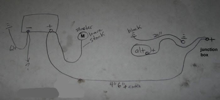
I was just measuring this stuff last night, take a look:
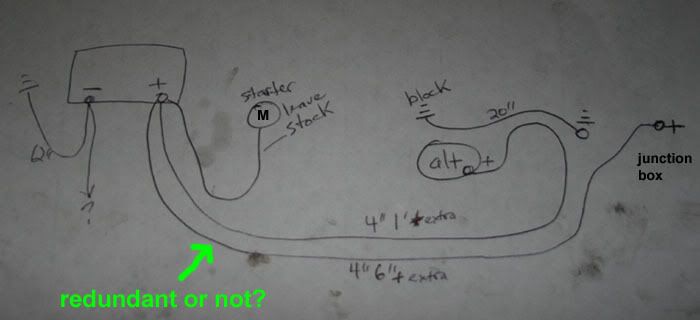
See the redundancy?
I was going to cut off the 2 wires on the POS side post leaving only the starter. Then run a 1/0ga to the alternator and a 1/0ga to my sound system. These 2 1/0ga wires would use a top mount post, like this:

or this:

I'd probably use 1/0ga for both grounds as well on the top post just to make everything match. It should look badass even though it is overkill.
Anyway, if I ran 2 wires to the drivers side it would cause a problem as I'd have too many 1/0ga wires on the battery post. I was thinking I could go from the battery to the junction box only and from there to the alt. Does that sound good to everyone here or would there be a problem?
More like this:
I also know that soldering the wires with large ring connectors would probably be the best choice over the life of the vehicle, but I was thinking of using the set screw type connectors like this:

Anyone think they would get lose or corrode or anything like that?
See the redundancy?
I was going to cut off the 2 wires on the POS side post leaving only the starter. Then run a 1/0ga to the alternator and a 1/0ga to my sound system. These 2 1/0ga wires would use a top mount post, like this:
or this:
I'd probably use 1/0ga for both grounds as well on the top post just to make everything match. It should look badass even though it is overkill.
Anyway, if I ran 2 wires to the drivers side it would cause a problem as I'd have too many 1/0ga wires on the battery post. I was thinking I could go from the battery to the junction box only and from there to the alt. Does that sound good to everyone here or would there be a problem?
More like this:
I also know that soldering the wires with large ring connectors would probably be the best choice over the life of the vehicle, but I was thinking of using the set screw type connectors like this:
Anyone think they would get lose or corrode or anything like that?
Last edited by JasonWW; 01-18-2007 at 12:33 PM.
01-18-2007, 02:22 PM
#26
TECH Fanatic
Join Date: Oct 2006
Location: Champaign/Chicagoland
Posts: 1,005
Likes: 0
Received 3 Likes
on
3 Posts
I think it may be better to have a direct line from the alternator to the battery to be sure of charge distribution.... You would be giving the moving charge the alternator outputs more paths (anything off the junction box) to choose from. However....the junction box is really just an extension of the battery terminal (same node)........so in that respect there isn't a difference...
08-06-2018, 05:01 PM
#28
Registered User

Join Date: Aug 2018
Location: Athens, Oh
Posts: 1
Likes: 0
Received 0 Likes
on
0 Posts
I know this post is a few days old but I was wondering if anyone had any new links for big 3 wiring kits. We are restoring a 92 z28 1le for my sons first car and will have upgraded stereo and lights as well as Dakota dash and I will be making charging units all around the car. I know how to do the wiring but due to some boo boo's from Iraq my hands hurt to much to cut n crimp so I'm being a wimp and just going to buy a kit. Thanks for any direction you can provide!
08-06-2018, 07:02 PM
#29
TECH Resident

http://innovativewiring.com/?page_id=182
That's the current link for the f-body set. Just scroll down to the version you need.
I ran them on my Caprice and helped install them on a couple others and they worked great. Install is tricky though because the cables don't flex much.
That's the current link for the f-body set. Just scroll down to the version you need.
I ran them on my Caprice and helped install them on a couple others and they worked great. Install is tricky though because the cables don't flex much.