Aftermarket control arms. Whats your opinion on this?
 02-08-2014, 07:41 PM
#41

FWIW, I would highly advise against the Creative Steel product, from a safety perspective. Drilling and tapping the bolts to thread Zerk grease fittings in there is severely weakening the bolt--a recipe for disaster. Maybe if they vastly increased the size of the bolt first (e.g. from a M12 to a M18), it might work, but GM sized those fasteners like that for a reason.
 02-09-2014, 10:17 AM
#43
FormerVendor

Join Date: Nov 2013
Location: Oregon
Posts: 212
Likes: 0
Received 0 Likes
on
0 Posts
FWIW, I would highly advise against the Creative Steel product, from a safety perspective. Drilling and tapping the bolts to thread Zerk grease fittings in there is severely weakening the bolt--a recipe for disaster. Maybe if they vastly increased the size of the bolt first (e.g. from a M12 to a M18), it might work, but GM sized those fasteners like that for a reason.
We did not invent this technique, we took it from another industry and applied it to a problem that all rotating urethane bushings have-- they squeak.
When we installed our control arm bushings on our car we torqued our grease-able bolts to the specified 130 ft lbs for a 14mm 10.9 and 80 lbs for
the 12mm 10.9. No special treatment or concessions were given.
Thank you for bringing up this topic Fuzz. Unless a person really digs deep and analyses what forces are put on a bolt and from what direction, most peoples gut feeling would say that drilling a bolt would weaken it. Fact's be known, the center "core" of a bolt is the least stressed cross section of material AND the material in the center of the bolt is relatively soft compared to the outside of the bolt. The case hardening process only penetrates .020 -.030 deep.
If you readers will notice, Creative Steel was no where in this thread. I was a lurker/spectator just like most of you. Fuzzy drug us in here, out of the clear blue sky to put a negative twist on one of our products. He has been a long time hater of ours, if you read his posts you will notice that he will never have something positive to say about us or our products. We are not alone. It would be staggering to know how many new guys to the forum he has driven away. Not to mention how many old timers he's offended.
02-09-2014, 11:43 AM
#44
Care to share your source of information that says drilling a small hole down the center of a bolt weakens it, especially it's tensile strength. If any of you guys have ever over tightened a bolt to the point of failure...where did it brake? It broke in the threaded section and probably right where the threads begin. When we drill the bolts we stay in the thicker unthreaded section of the bolt.
When we installed our control arm bushings on our car we torqued our grease-able bolts to the specified 130 ft lbs for a 14mm 10.9 and 80 lbs for the 12mm 10.9. No special treatment or concessions were given.
Thank you for bringing up this topic Fuzz. Unless a person really digs deep and analyses what forces are put on a bolt and from what direction, most peoples gut feeling would say that drilling a bolt would weaken it. Fact's be known, the center "core" of a bolt is the least stressed cross section of material AND the material in the center of the bolt is relatively soft compared to the outside of the bolt. The case hardening process only penetrates .020 -.030 deep.
If you readers will notice, Creative Steel was no where in this thread. I was a lurker/spectator just like most of you. Fuzzy drug us in here, out of the clear blue sky to put a negative twist on one of our products. He has been a long time hater of ours, if you read his posts you will notice that he will never have something positive to say about us or our products. We are not alone. It would be staggering to know how many new guys to the forum he has driven away. Not to mention how many old timers he's offended.
It's frankly disgusting how you alternately borrow my words and my ideas when it's convenient and make unsupportable accusations when they're not. Get off my case. I've bought your motor mounts, your shifter bushings, and your differential bushing. Your tools and your instructions are awesome, but those older versions of your products were not up to the job. You appear to think (largely based on posts on the Cadillac Forums) that I'm on a vendetta to get you, paid by Revshift, or some such nonsense. I'm not. I argue with everyone--especially the people that I like! I may be harsh in my criticism, but I try to be as strongly positive when I have a good experience with a product. I don't know whether that day will come between me and you guys, but these "conversations" are not helping.
I have a strict "no-BS" policy. If you want to show that my concerns are baseless or that some (or all) of my assumptions are incorrect, have at it. I'll be happy to admit that I'm wrong, and I might consider buying your control arm bushings, since it's frustrating trying to find the perfect lubricant for my 95A Revshift control arm bushings.
FWIW, according to Darkman's post on the Cadillac Forums, the torque spec on the yoke-to-UCA bolts is 66 ft-lbs, not 80 ft-lbs. I found that the lower control arm bolt torque spec is 111 ft-lbs, not 130 ft-lbs.
Originally Posted by Creative Steel Website
NOTE: The stock OEM bushings have torsional resistance because the metal insert is molded to the rubber; our bushings allow the metal insert to spin freely. If you are running aftermarket springs/shocks, you may need to adjust them for this factor.
Originally Posted by FuzzyLogic
The other thing is that the Revshift bushings, unlike the stock bushings, permit full rotation of the control arms. I'm sure you've noticed this already--if you try to push your control arms up or down while doing maintenance, they'll spring back to their original position. The control arms require a massive amount of effort to move them more than a couple of inches, because you're effectively twisting the rubber inside the OEM bushings. This affects your spring rates--making them progressive instead of linear, assuming that you ditched the OEM suspension. If you're lowered like I am, you may be surprised to find that you have to readjust your ride height settings, since the original bushings were supporting a significant amount of weight (somewhere in the ballpark of 200 lbs per corner).
The downside is that these bushings are not maintenance free. All polyurethane control arm bushings squeak when they run out of lubricant, since the application twists the bushing around its steel or aluminum core. I've had to re-grease my bushings twice now (every four months or so) using the Revshift-recommended lubricant (Energy Suspension Formula 5). I've already purchased a couple of PTFE-based alternatives (e.g. marine-type stuff), and will report back with my findings. But it may take a couple of months to know whether there was an improvement.
The downside is that these bushings are not maintenance free. All polyurethane control arm bushings squeak when they run out of lubricant, since the application twists the bushing around its steel or aluminum core. I've had to re-grease my bushings twice now (every four months or so) using the Revshift-recommended lubricant (Energy Suspension Formula 5). I've already purchased a couple of PTFE-based alternatives (e.g. marine-type stuff), and will report back with my findings. But it may take a couple of months to know whether there was an improvement.
Control arm fasteners are employed in shear and tension. And just because you can torque it down once or twice doesn't mean it won't fail later or in shear. I have a lot of experience with this, since I take my wheels off every other weekend on average (I'm on my third set of lug studs). Every single lug stud I've broken has sheared at the base of the threaded section, because the first two threads in 60 degree [conventional] threaded fasteners can take over 75% of the applied load. So it's a good thing that CS isn't drilling that deep into the bolt.

Conventional 60 degree thread left, Spiralock fastener right
So let's look at tension in the drilled section of the fastener:
The strength of a rod (hollow or solid) employed in tension is related to its cross-sectional area. If you took a M12 (12mm diameter) bolt and drilled it out using a 3/16" bit (4.7625mm diameter), its cross sectional area would be:
- Area 1 = pi*6^2 = 113 in^2
- Area 2 = pi*2.38^2 = 17.8 in^2
Cross sectional area = Area 1 - Area 2 = 95.2 in^2 (84.2% of original strength)
Your Class 10.9 fastener (1040 MPa tensile strength) now falls somewhere between a Class 9.8 (900 MPa) and 8.8 (830 MPa) fastener.
Now we'll take the same example and look at the bending moment of the same, modified fastener. The moment of inertia for a rod in shear is also related to its cross sectional area.
- I_rod = (1/4)*6^4 = 324 in^4
- I_tube = (1/4)*(6^4 - 2.38^4) = 316 in^4 (97.5% of original strength)
So, to Creative Steel's point, there doesn't appear to be a whole lot of difference between a hollow tube versus a solid rod employed in shear.
However, you have to assume (since pictures aren't provided) that Creative Steel also added a row of ports along the length of the bolt to distribute the grease inside the bushing. Otherwise, the grease can't get to where it needs to go. This is aspect of the design that has the potential to really mess up the bending resistance AND tensile strength of the fastener, especially if those fasteners were drilled straight through (from side to side). There are published books (e.g. ) describing localized stress intensity factors based on material imperfections.
This kind of stuff is pretty much out of the league of a forum discussion (e.g. when this is addressed in the structural design of a component, I'm usually looking at a CFD analysis), but it could be addressed by Creative Steel through testing. Personally, I would never want to install a bolt like this without a significant amount of assurance that it's been tested to failure and will handle the kind of beating we put on our cars. Control arms are one of those things you never want to fail--if you lose a control arm going around a corner, you will totally lose control of the car and, depending on the situation, you could be seriously hurt (or die).
The following examples are similar, but not the same as what might happen if you lose a control arm. My point in sharing these examples is not to be a fear monger, but rather to show that these kinds of failure DO happen, and to advise all necessary precautions when considering what appears to be (correct me if I'm wrong, Creative Steel) an product that has not been tested (other than a "yep, the bolt didn't snap when we torqued it down--must be fine!") in an application that is critical to your safety.
Watch what happens at 1:41. Fortunately, this was only a rear control arm--he still had steering.
Skip to 1:15--watch what happens to the steering wheel. In this case, the lower ball joint attached to the tie rod broke.
http://digitaljournal.com/article/333940
Last edited by FuzzyLog1c; 02-09-2014 at 12:39 PM.
02-09-2014, 12:52 PM
#45
TECH Fanatic

Holy technical explanation batman. Lol... Fuzzy, I need you to draw me more pictures dude... So I can understand 
I would not worry about the squeaks dude. A little grease will fix it right up. I believe the revshift bushings have grease that comes with them. Then get a bunch if lithium grease and grease them when they start to squeak. Not a big deal really.
I would not worry about the squeaks dude. A little grease will fix it right up. I believe the revshift bushings have grease that comes with them. Then get a bunch if lithium grease and grease them when they start to squeak. Not a big deal really.
02-09-2014, 01:55 PM
#46
FormerVendor
Join Date: Nov 2013
Location: Oregon
Posts: 212
Likes: 0
Received 0 Likes
on
0 Posts
Oh please. You did something technically questionable and now you're attacking me rather than addressing the issue. My criticism of your control arm bushing design--specifically the feature intended reduce the hassle of control arm bushings squeaking--was inherently relevant to the topic under discussion.
It's frankly disgusting how you alternately borrow my words and my ideas when it's convenient and make unsupportable accusations when they're not. Get off my case. I've bought your motor mounts, your shifter bushings, and your differential bushing. Your tools and your instructions are awesome, but those older versions of your products were not up to the job. You appear to think (largely based on posts on the Cadillac Forums) that I'm on a vendetta to get you, paid by Revshift, or some such nonsense. I'm not. I argue with everyone--especially the people that I like! I may be harsh in my criticism, but I try to be as strongly positive when I have a good experience with a product. I don't know whether that day will come between me and you guys, but these "conversations" are not helping.
I have a strict "no-BS" policy. If you want to show that my concerns are baseless or that some (or all) of my assumptions are incorrect, have at it. I'll be happy to admit that I'm wrong, and I might consider buying your control arm bushings, since it's frustrating trying to find the perfect lubricant for my 95A Revshift control arm bushings.
FWIW, according to Darkman's post on the Cadillac Forums, the torque spec on the yoke-to-UCA bolts is 66 ft-lbs, not 80 ft-lbs. I found that the lower control arm bolt torque spec is 111 ft-lbs, not 130 ft-lbs.
https://ls1tech.com/forums/17898496-post13.html
Control arm fasteners are employed in shear and tension. And just because you can torque it down once or twice doesn't mean it won't fail later or in shear. I have a lot of experience with this, since I take my wheels off every other weekend on average (I'm on my third set of lug studs). Every single lug stud I've broken has sheared at the base of the threaded section, because the first two threads in 60 degree [conventional] threaded fasteners can take over 75% of the applied load. So it's a good thing that CS isn't drilling that deep into the bolt.
Conventional 60 degree thread left, Spiralock fastener right
So let's look at tension in the drilled section of the fastener:
The strength of a rod (hollow or solid) employed in tension is related to its cross-sectional area. If you took a M12 (12mm diameter) bolt and drilled it out using a 3/16" bit (4.7625mm diameter), its cross sectional area would be:
Cross sectional area = Area 1 - Area 2 = 95.2 in^2 (84.2% of original strength)
Just because we have removed 16% of the material doesn't mean we have remove 16% of the strength. The center section that we remove is the lowest stressed cross section of the bolt.
Your Class 10.9 fastener (1040 MPa tensile strength) now falls somewhere between a Class 9.8 (900 MPa) and 8.8 (830 MPa) fastener.
GM has done away with all of the 14mm bolts in the rear suspension of the 2010 and new Camaros. Everything is now a 12mm, all of it. So even if we did lower the strength of a 14mm 10.9 bolt to the equivalent of an 8.8 grade bolt it would be just fine since the torque spec on a 12mm 10.9 is still lower than a 14mm 8.8.
Now we'll take the same example and look at the bending moment of the same, modified fastener. The moment of inertia for a rod in shear is also related to its cross sectional area.
So, to Creative Steel's point, there doesn't appear to be a whole lot of difference between a hollow tube versus a solid rod employed in shear.
However, you have to assume (since pictures aren't provided) that Creative Steel also added a row of ports along the length of the bolt to distribute the grease inside the bushing. Otherwise, the grease can't get to where it needs to go. This is aspect of the design that has the potential to really mess up the bending resistance AND tensile strength of the fastener, especially if those fasteners were drilled straight through (from side to side). There are published books (e.g. Stress Intensity Factors Handbook by Y. Murakami) describing localized stress intensity factors based on material imperfections.
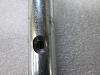
We put one 1/8" cross drill hole in the bolts for grease to pass through. No need for a row of holes. It is drilled through one side of the bolt, not both sides. There is no reason to drill through both sides. The grease will follow the path of least resistance, if you give it a path out of the bolt and out of the center tube that the bolt passes through it will find it's way to the urethane bushing.
This kind of stuff is pretty much out of the league of a forum discussion (e.g. when this is addressed in the structural design of a component, I'm usually looking at a CFD analysis), but it could be addressed by Creative Steel through testing. Personally, I would never want to install a bolt like this without a significant amount of assurance that it's been tested to failure and will handle the kind of beating we put on our cars. Control arms are one of those things you never want to fail--if you lose a control arm going around a corner, you will totally lose control of the car and, depending on the situation, you could be seriously hurt (or die).
The "beating that we put on our cars" doesn't put that much of a load on the bolts that connect the control arms to the cradle. The overwhelming majority of the vertical load is exerted out by the hub where the strut mounts. The bolts and bushings act more as a hinge point.
The following examples are similar, but not the same as what might happen if you lose a control arm. My point in sharing these examples is not to be a fear monger, but rather to show that these kinds of failure DO happen, and to advise all necessary precautions when considering what appears to be (correct me if I'm wrong, Creative Steel) an product that has not been tested (other than a "yep, the bolt didn't snap when we torqued it down--must be fine!") in an application that is critical to your safety
It's frankly disgusting how you alternately borrow my words and my ideas when it's convenient and make unsupportable accusations when they're not. Get off my case. I've bought your motor mounts, your shifter bushings, and your differential bushing. Your tools and your instructions are awesome, but those older versions of your products were not up to the job. You appear to think (largely based on posts on the Cadillac Forums) that I'm on a vendetta to get you, paid by Revshift, or some such nonsense. I'm not. I argue with everyone--especially the people that I like! I may be harsh in my criticism, but I try to be as strongly positive when I have a good experience with a product. I don't know whether that day will come between me and you guys, but these "conversations" are not helping.
I have a strict "no-BS" policy. If you want to show that my concerns are baseless or that some (or all) of my assumptions are incorrect, have at it. I'll be happy to admit that I'm wrong, and I might consider buying your control arm bushings, since it's frustrating trying to find the perfect lubricant for my 95A Revshift control arm bushings.
FWIW, according to Darkman's post on the Cadillac Forums, the torque spec on the yoke-to-UCA bolts is 66 ft-lbs, not 80 ft-lbs. I found that the lower control arm bolt torque spec is 111 ft-lbs, not 130 ft-lbs.
https://ls1tech.com/forums/17898496-post13.html
Control arm fasteners are employed in shear and tension. And just because you can torque it down once or twice doesn't mean it won't fail later or in shear. I have a lot of experience with this, since I take my wheels off every other weekend on average (I'm on my third set of lug studs). Every single lug stud I've broken has sheared at the base of the threaded section, because the first two threads in 60 degree [conventional] threaded fasteners can take over 75% of the applied load. So it's a good thing that CS isn't drilling that deep into the bolt.
Conventional 60 degree thread left, Spiralock fastener right
So let's look at tension in the drilled section of the fastener:
The strength of a rod (hollow or solid) employed in tension is related to its cross-sectional area. If you took a M12 (12mm diameter) bolt and drilled it out using a 3/16" bit (4.7625mm diameter), its cross sectional area would be:
- Area 1 = pi*6^2 = 113 in^2
- Area 2 = pi*2.38^2 = 17.8 in^2
Cross sectional area = Area 1 - Area 2 = 95.2 in^2 (84.2% of original strength)
Just because we have removed 16% of the material doesn't mean we have remove 16% of the strength. The center section that we remove is the lowest stressed cross section of the bolt.
Your Class 10.9 fastener (1040 MPa tensile strength) now falls somewhere between a Class 9.8 (900 MPa) and 8.8 (830 MPa) fastener.
GM has done away with all of the 14mm bolts in the rear suspension of the 2010 and new Camaros. Everything is now a 12mm, all of it. So even if we did lower the strength of a 14mm 10.9 bolt to the equivalent of an 8.8 grade bolt it would be just fine since the torque spec on a 12mm 10.9 is still lower than a 14mm 8.8.
Now we'll take the same example and look at the bending moment of the same, modified fastener. The moment of inertia for a rod in shear is also related to its cross sectional area.
- I_rod = (1/4)*6^4 = 324 in^4
- I_tube = (1/4)*(6^4 - 2.38^4) = 316 in^4 (97.5% of original strength)
So, to Creative Steel's point, there doesn't appear to be a whole lot of difference between a hollow tube versus a solid rod employed in shear.
However, you have to assume (since pictures aren't provided) that Creative Steel also added a row of ports along the length of the bolt to distribute the grease inside the bushing. Otherwise, the grease can't get to where it needs to go. This is aspect of the design that has the potential to really mess up the bending resistance AND tensile strength of the fastener, especially if those fasteners were drilled straight through (from side to side). There are published books (e.g. Stress Intensity Factors Handbook by Y. Murakami) describing localized stress intensity factors based on material imperfections.
We put one 1/8" cross drill hole in the bolts for grease to pass through. No need for a row of holes. It is drilled through one side of the bolt, not both sides. There is no reason to drill through both sides. The grease will follow the path of least resistance, if you give it a path out of the bolt and out of the center tube that the bolt passes through it will find it's way to the urethane bushing.
This kind of stuff is pretty much out of the league of a forum discussion (e.g. when this is addressed in the structural design of a component, I'm usually looking at a CFD analysis), but it could be addressed by Creative Steel through testing. Personally, I would never want to install a bolt like this without a significant amount of assurance that it's been tested to failure and will handle the kind of beating we put on our cars. Control arms are one of those things you never want to fail--if you lose a control arm going around a corner, you will totally lose control of the car and, depending on the situation, you could be seriously hurt (or die).
The "beating that we put on our cars" doesn't put that much of a load on the bolts that connect the control arms to the cradle. The overwhelming majority of the vertical load is exerted out by the hub where the strut mounts. The bolts and bushings act more as a hinge point.
The following examples are similar, but not the same as what might happen if you lose a control arm. My point in sharing these examples is not to be a fear monger, but rather to show that these kinds of failure DO happen, and to advise all necessary precautions when considering what appears to be (correct me if I'm wrong, Creative Steel) an product that has not been tested (other than a "yep, the bolt didn't snap when we torqued it down--must be fine!") in an application that is critical to your safety
How would you like us to test these bolts after drilling and tapping to be considered safe ? According to the info you got from Darkman I have already over torqued them without failure.
Tomorrow I will torque 5, 12mm and 5, 14mm 10.9 bolts to failure. Then I will torque 5 drilled and tapped bolts until failure. I will report back.
02-09-2014, 02:10 PM
#48
Oh please. You did something technically questionable and now you're attacking me rather than addressing the issue. My criticism of your control arm bushing design--specifically the feature intended reduce the hassle of control arm bushings squeaking--was inherently relevant to the topic under discussion.
It's frankly disgusting how you alternately borrow my words and my ideas when it's convenient and make unsupportable accusations when they're not. Get off my case. I've bought your motor mounts, your shifter bushings, and your differential bushing. Your tools and your instructions are awesome, but those older versions of your products were not up to the job. You appear to think (largely based on posts on the Cadillac Forums) that I'm on a vendetta to get you, paid by Revshift, or some such nonsense. I'm not. I argue with everyone--especially the people that I like! I may be harsh in my criticism, but I try to be as strongly positive when I have a good experience with a product. I don't know whether that day will come between me and you guys, but these "conversations" are not helping.
I have a strict "no-BS" policy. If you want to show that my concerns are baseless or that some (or all) of my assumptions are incorrect, have at it. I'll be happy to admit that I'm wrong, and I might consider buying your control arm bushings, since it's frustrating trying to find the perfect lubricant for my 95A Revshift control arm bushings.
FWIW, according to Darkman's post on the Cadillac Forums, the torque spec on the yoke-to-UCA bolts is 66 ft-lbs, not 80 ft-lbs. I found that the lower control arm bolt torque spec is 111 ft-lbs, not 130 ft-lbs.
https://ls1tech.com/forums/17898496-post13.html
Control arm fasteners are employed in shear and tension. And just because you can torque it down once or twice doesn't mean it won't fail later or in shear. I have a lot of experience with this, since I take my wheels off every other weekend on average (I'm on my third set of lug studs). Every single lug stud I've broken has sheared at the base of the threaded section, because the first two threads in 60 degree [conventional] threaded fasteners can take over 75% of the applied load. So it's a good thing that CS isn't drilling that deep into the bolt.
Conventional 60 degree thread left, Spiralock fastener right
So let's look at tension in the drilled section of the fastener:
The strength of a rod (hollow or solid) employed in tension is related to its cross-sectional area. If you took a M12 (12mm diameter) bolt and drilled it out using a 3/16" bit (4.7625mm diameter), its cross sectional area would be:
Cross sectional area = Area 1 - Area 2 = 95.2 in^2 (84.2% of original strength)
Your Class 10.9 fastener (1040 MPa tensile strength) now falls somewhere between a Class 9.8 (900 MPa) and 8.8 (830 MPa) fastener.
Now we'll take the same example and look at the bending moment of the same, modified fastener. The moment of inertia for a rod in shear is also related to its cross sectional area.
So, to Creative Steel's point, there doesn't appear to be a whole lot of difference between a hollow tube versus a solid rod employed in shear.
However, you have to assume (since pictures aren't provided) that Creative Steel also added a row of ports along the length of the bolt to distribute the grease inside the bushing. Otherwise, the grease can't get to where it needs to go. This is aspect of the design that has the potential to really mess up the bending resistance AND tensile strength of the fastener, especially if those fasteners were drilled straight through (from side to side). There are published books (e.g. Stress Intensity Factors Handbook by Y. Murakami) describing localized stress intensity factors based on material imperfections.
This kind of stuff is pretty much out of the league of a forum discussion (e.g. when this is addressed in the structural design of a component, I'm usually looking at a CFD analysis), but it could be addressed by Creative Steel through testing. Personally, I would never want to install a bolt like this without a significant amount of assurance that it's been tested to failure and will handle the kind of beating we put on our cars. Control arms are one of those things you never want to fail--if you lose a control arm going around a corner, you will totally lose control of the car and, depending on the situation, you could be seriously hurt (or die).
The following examples are similar, but not the same as what might happen if you lose a control arm. My point in sharing these examples is not to be a fear monger, but rather to show that these kinds of failure DO happen, and to advise all necessary precautions when considering what appears to be (correct me if I'm wrong, Creative Steel) an product that has not been tested (other than a "yep, the bolt didn't snap when we torqued it down--must be fine!") in an application that is critical to your safety.
It's frankly disgusting how you alternately borrow my words and my ideas when it's convenient and make unsupportable accusations when they're not. Get off my case. I've bought your motor mounts, your shifter bushings, and your differential bushing. Your tools and your instructions are awesome, but those older versions of your products were not up to the job. You appear to think (largely based on posts on the Cadillac Forums) that I'm on a vendetta to get you, paid by Revshift, or some such nonsense. I'm not. I argue with everyone--especially the people that I like! I may be harsh in my criticism, but I try to be as strongly positive when I have a good experience with a product. I don't know whether that day will come between me and you guys, but these "conversations" are not helping.
I have a strict "no-BS" policy. If you want to show that my concerns are baseless or that some (or all) of my assumptions are incorrect, have at it. I'll be happy to admit that I'm wrong, and I might consider buying your control arm bushings, since it's frustrating trying to find the perfect lubricant for my 95A Revshift control arm bushings.
FWIW, according to Darkman's post on the Cadillac Forums, the torque spec on the yoke-to-UCA bolts is 66 ft-lbs, not 80 ft-lbs. I found that the lower control arm bolt torque spec is 111 ft-lbs, not 130 ft-lbs.
https://ls1tech.com/forums/17898496-post13.html
Control arm fasteners are employed in shear and tension. And just because you can torque it down once or twice doesn't mean it won't fail later or in shear. I have a lot of experience with this, since I take my wheels off every other weekend on average (I'm on my third set of lug studs). Every single lug stud I've broken has sheared at the base of the threaded section, because the first two threads in 60 degree [conventional] threaded fasteners can take over 75% of the applied load. So it's a good thing that CS isn't drilling that deep into the bolt.
Conventional 60 degree thread left, Spiralock fastener right
So let's look at tension in the drilled section of the fastener:
The strength of a rod (hollow or solid) employed in tension is related to its cross-sectional area. If you took a M12 (12mm diameter) bolt and drilled it out using a 3/16" bit (4.7625mm diameter), its cross sectional area would be:
- Area 1 = pi*6^2 = 113 in^2
- Area 2 = pi*2.38^2 = 17.8 in^2
Cross sectional area = Area 1 - Area 2 = 95.2 in^2 (84.2% of original strength)
Your Class 10.9 fastener (1040 MPa tensile strength) now falls somewhere between a Class 9.8 (900 MPa) and 8.8 (830 MPa) fastener.
Now we'll take the same example and look at the bending moment of the same, modified fastener. The moment of inertia for a rod in shear is also related to its cross sectional area.
- I_rod = (1/4)*6^4 = 324 in^4
- I_tube = (1/4)*(6^4 - 2.38^4) = 316 in^4 (97.5% of original strength)
So, to Creative Steel's point, there doesn't appear to be a whole lot of difference between a hollow tube versus a solid rod employed in shear.
However, you have to assume (since pictures aren't provided) that Creative Steel also added a row of ports along the length of the bolt to distribute the grease inside the bushing. Otherwise, the grease can't get to where it needs to go. This is aspect of the design that has the potential to really mess up the bending resistance AND tensile strength of the fastener, especially if those fasteners were drilled straight through (from side to side). There are published books (e.g. Stress Intensity Factors Handbook by Y. Murakami) describing localized stress intensity factors based on material imperfections.
This kind of stuff is pretty much out of the league of a forum discussion (e.g. when this is addressed in the structural design of a component, I'm usually looking at a CFD analysis), but it could be addressed by Creative Steel through testing. Personally, I would never want to install a bolt like this without a significant amount of assurance that it's been tested to failure and will handle the kind of beating we put on our cars. Control arms are one of those things you never want to fail--if you lose a control arm going around a corner, you will totally lose control of the car and, depending on the situation, you could be seriously hurt (or die).
The following examples are similar, but not the same as what might happen if you lose a control arm. My point in sharing these examples is not to be a fear monger, but rather to show that these kinds of failure DO happen, and to advise all necessary precautions when considering what appears to be (correct me if I'm wrong, Creative Steel) an product that has not been tested (other than a "yep, the bolt didn't snap when we torqued it down--must be fine!") in an application that is critical to your safety.
Well if we want to get into a technical discussion:
The tensile area of the unthreaded portion of the bolt with a hole in the middle is still larger than that of the thread root area (IE the smallest portion of the bolt where the base of the thread cut is) so tensile strength is really no different.
Root area of a M12 = PI*.194^2=76 mm^2
From your calculations the shank portion of the bolt with a hole in it has an area of 96 mm^2
(PS Fix your units, you input mm, so your areas are mm^2, not in^2)
Still the same weak point in tensile loading
You mention bolts failing after multiple torque cycles. As long as they are not torqued beyond their yield point this should not be an issue (I would have to verify with the factory manual that these are not torque to yield, lug studs definitely are not) Steel has an infinite fatigue life, so as long as the applied torque value stays below this limit there should never be an issue (also noting that a properly torqued bolted joint will never exceed the preload on the bold generated during the initial torqueing) Your lug studs are most likely breaking from a combination of wear and over torqueing. (I doubt the control arm bushings will be loosened and tightened enough to make wear an issue.
The shear strength of the fastener will be slightly less as you noted (the cross sectional area applies here as well), but this is also CS�s point that the small hole in the center has as minimal effect. A properly bolted joint relies mostly on the friction generated by the tensile load on the bolt to keep the joint tight, so while the bolt is loaded in double shear a great portion of the load is reacted by the friction force at the mating surface due to the tensile load.
The grease holes drilled perpendicular to the bolt could reduce the tensile capabilities of the bolt, but again those loads will never exceed the preload applied to the bolt, the bolt will not be bending during use.
These fasteners all have such a large margin of safety in them, that the minute reduction from these grease ports should not concern you. It would not surprise me if some of those failures you have seen were due to a poor job of adding the grease ports (guy doing it at home w/o a lathe, etc
Also just a note, I would look for an FEA (finite element analysis) not a CFD (Computational fluid dynamics) to show the stresses in the bolt.
Overall, will a bolt w/o holes in it be stronger: YES� will reasonably sized grease ports/holes cause an issue: NO
Don�t get me wrong, these fasteners are safety critical and should be professionally made, but I do not doubt that Creative steal has done this. Although If I was selling them I might send a few off to an independent lab to verify this to CYA in case there ever is an issue.
 02-09-2014, 02:36 PM
#50
I put my responses to the different points of your post above in bold
How would you like us to test these bolts after drilling and tapping to be considered safe ? According to the info you got from Darkman I have already over torqued them without failure.
Tomorrow I will torque 5, 12mm and 5, 14mm 10.9 bolts to failure. Then I will torque 5 drilled and tapped bolts until failure. I will report back.
http://www.fastenal.com/content/feds...t%20Design.pdf
If you look at the Tensile Stress-Strain Diagram on page 2 (and you can corroborate this with other sources if you don't trust me), typical clamp loads are typically about 75-80% of the bolt's yield strain, beyond which plastic deformation occurs. With a 1/8" center hole, I think you're down to 92% (see Question #1, below) not counting the hole in the side.
According to this PDF, I believe you're probably good based on the assertion that 75-80% of the yield strain is achieved at 105 ft-lbs (143 N-m) and 115 ft-lbs (156 N-m) for a coarse and fine thread, Class 10.9, M12 bolt, respectively. Since the GM torque spec is only 66 ft-lbs, drilling out the center still leaves you with a maximum recommended torque of 96.6 ft-lbs (coarse thread). The only thing I would want to see is whether that modified fastener was significantly weaker due to the hole in the side.
Follow up questions:
- Where is it said that tension is distributed unequally around the circumference of a fastener? Before it's drilled out, that is.

- The point about the 14mm --> 12mm bolts doesn't apply to the CTS-V front upper control arms, which are already 12mm.
- Where is the grease port located relative to the bushing? The pictures make it look like the bushing extends all the way through the arm, and then there's a (not pictured) polyurethane cap on the other side. There must be something drilled in the metal sleeve to permit grease to get to the polyurethane bushing, otherwise, you're just greasing the bolt/sleeve interface. Also, what's stopping the grease from just squirting out the ends?
- Agreed that the bushings act like hinge points, which is a major reason why I want to see very hard (Shore 60D or 75D) bushings there to improve performance and avoid the need for Zerk fittings in the first place. But your argument seems to have neglected the fact that, knowing how these bolts were going to be stressed, GM chose M12 or M14 bolts. It's not like they chose bolts that could handle the load directly and applied them to a hinge.
Were either of those vehicles a CTS-V?
Last edited by FuzzyLog1c; 02-09-2014 at 03:18 PM.
02-09-2014, 02:40 PM
#51
Not to get into this argument but drilled zerk bolts have been used for decades. They realistically only need one feed hole. The grease pressure and the pivot action of the bolt spreads the grease throughout the bushing.
Both of you guys have valid points but in reality how many times are you really gonna take the control arms off? If the bolt makes you nervous you can always replace these anytime you remove the arm after initial install.
Both of you guys have valid points but in reality how many times are you really gonna take the control arms off? If the bolt makes you nervous you can always replace these anytime you remove the arm after initial install.


 02-09-2014, 03:10 PM
#54
TECH Fanatic
The urethane doesn't wear like rubber. So the graphite will be isolated inside the urethane bushings and not creating as much lubrication as intended. The grease able fittings in the arm itself to me is the better alternative. And the way I have gone before... And the way I intend to do with the V
02-09-2014, 03:25 PM
#55
Not to get into this argument but drilled zerk bolts have been used for decades. They realistically only need one feed hole. The grease pressure and the pivot action of the bolt spreads the grease throughout the bushing.
Both of you guys have valid points but in reality how many times are you really gonna take the control arms off? If the bolt makes you nervous you can always replace these anytime you remove the arm after initial install.
Both of you guys have valid points but in reality how many times are you really gonna take the control arms off? If the bolt makes you nervous you can always replace these anytime you remove the arm after initial install.
But your question, "how many times are you going to take these control arms off," is a very pertinent one. Without an easy way to lubricate the Revshift bushings, I've had them off every couple of months. Assuming Creative Steel's solution works well, the only time you'll be taking the uppers off is to replace the ball joint every other year or so.
Last edited by FuzzyLog1c; 02-09-2014 at 03:31 PM.
02-09-2014, 03:39 PM
#56
Launching!
Thread Starter
iTrader: (3)

Join Date: Dec 2010
Location: OR
Posts: 254
Likes: 0
Received 0 Likes
on
0 Posts
The urethane doesn't wear like rubber. So the graphite will be isolated inside the urethane bushings and not creating as much lubrication as intended. The grease able fittings in the arm itself to me is the better alternative. And the way I have gone before... And the way I intend to do with the V
there is a thread right now about it on this forum. I might get me some bushings and go this route. just gotta figure out the techs on how deep to go.
54inches. thanks for the answer. I'll be buying some all joints soon. these need to be pressed out right.
Also moog or raybestos? or are they the same?
02-19-2014, 12:18 PM
#58
FormerVendor
Join Date: Nov 2013
Location: Oregon
Posts: 212
Likes: 0
Received 0 Likes
on
0 Posts
I apologize for such a late response, things have been busy. Lets get to some typing!
The first 20 seconds will show you that the inside of the bolt is the least affected portion of the bolt in tension:
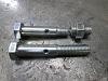
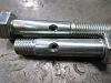
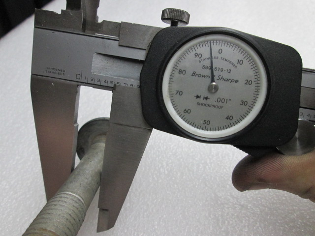
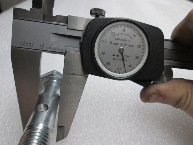
Here are some pictures of the bolts:
Front upper control arm:
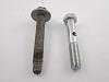
Front lower control arm:
Ours:

As you can see, the FUCA bolt is a tap bolt(no shoulder), and on the FLCA bolt, the areas that are in double shear are the thicker sections.
Holy bending, Batman!
It should be noted that all control arm bolts are in double shear, resulting in no possible way of bending. Also with a 1.250" OD x .375" wall x ~1.500" sleeve, it isn't going to bend. Definitely when the load is spread across the entire sleeve and not at the center point. It would also take a lot of force to bend the mounting ears while the bolt is torqued down to 60+ fb/lbs. So I believe bending is out of the question. As for the bolt being in double shear, the perpendicular grease port is not located in a shear plane, so it has no ill effects. With the OEM Front Upper Control Arm bolts being a tap bolt, they have roughly 80% of the area as our bolt with a shoulder that is drilled out.
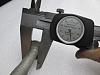
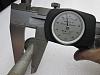
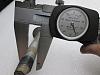
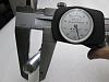
We torqued a 14mm drilled bolt to 240ft/lbs trying to snap it. We had to back it off, try to torque to 250ft/lbs and the bolt finally broke on the inside of the threads(nowhere near the drilled area). There was no deformation on the drilled hole, nor was the bolt bent. Later found the nut was galled onto the threads, which most likely caused the bolt to twist apart without it adding more torque on the bolt.
We then torqued a new bolt down to 180ft/lbs before we noticed a very slight deformation. This is 50ft/lbs past the rating of the bolt, as well as almost past any torque spec on the entire vehicle(besides 16mm subframe bolt).
It is A LOT easier to say something isn't going to work then to do the research and find the answer. It is also easier to throw questions out without having to do any work.
1.) I have no clue??? Google that ****.
2.) I actually need to recant this statement as it is not true, I apologize. They use 12mm AND 14mm bolts, however the heads are all 18mm.
3.) Why does there have to be a cap?
This is where being mechanically-oriented doesn't mean you know everything. Yes, there are THREE grease ports, technically, between the zirk and the polyurethane bushing. One in the bolt and two in the metal insert. That allows the grease to flow through the bolt, through or filling up the tube(tolerances are close that it isn't a waste), and finally reaching the polyurethane bushing. There doesn't need to be a "cap" to capture grease as the metal insert is a slight press fit into the bushings. This press fit makes the grease go to the least resistance, out toward the flanged side of the bushing into the grease grooves. The stainless plates trap the grease in. Once the grease pushes all the air out, wipe it off. Grease is thick enough that it won't just drip out.
If you use a two piece bushing design, your metal inserts will have to be oversized enough so that there is no side load on the bushing flanges. That would mean the bushing toward the rear wouldn't be doing part of its job, keeping the wheel centered while braking. The lower control arm also isn't machined on the inside of the arm; one side is tapered while the other comes to a point in the centerline of the bushing. Both those changes will cause the arm to bind on the bushing if there is an axial load on the bushing flanges.
4.) GM chose the highest safety factor before the bean counters stepped in. Having that much liability however, I doubt they would put a bolt in that barely surpasses the testing.
Urethane is kind of a subject that no one knows about, but once they read a wiki page, they are an "expert". Raising the Shore hardness closer to Delrin does NOT mean it will act like Delrin. Urethane, no matter what hardness, is NOT self lubricating. Self Lubricating being a term that is just tossed out there in respect to Friction Coefficient. Now, generally as the shore rating of the urethane raises(urethane gets harder) all the attributes get better and generally the friction coefficient goes down and is able to reach the same levels as Delrin (0.2). As the urethane gets higher attributes, the heat resistance also gets better. However, if this point is ever reached, the urethane WILL NOT lube itself. It will become sticky and gummy, doing quite the opposite of what you want. A stiffer urethane MAY decrease how often you grease your bushings, but they will still need to be greased.
As for just tossing in graphite to make a bushing self lubricating, it is a marketing ploy. I have them on my Chevelle; I can video them squeak as I push the hood down half an inch. For one, the graphite would have to be between the metal insert and the urethane. That is hard to cast, as the graphite would be mixed throughout the urethane. Also, anything added to urethane is an impurity. Yes, even colorant(even though the effect is very miniscule. But no one wants Clear/Amber bushings). So, adding a filler can increase some properties of urethane, however it will decrease others as a result.
For some it may be, and that is fine. However, as a company and an owner of the car, I cannot tell a customer, "Well, all you can do is pull them off and regrease them every month. Or, you can go out of your way, buy more tools and take up your own personal time to drill and tap your control arms for a zirk fitting because our design is really great!" Urethane squeaks, and lube eventually runs dry. We took a known idea from a different industry and applied it to solve a large problem. Now the guy has to do no extra work outside installing the part.
The first 20 seconds will show you that the inside of the bolt is the least affected portion of the bolt in tension:
Here are some pictures of the bolts:
Front upper control arm:

Front lower control arm:


Ours:

As you can see, the FUCA bolt is a tap bolt(no shoulder), and on the FLCA bolt, the areas that are in double shear are the thicker sections.
Now we'll take the same example and look at the bending moment of the same, modified fastener.
This is aspect of the design that has the potential to really mess up the bending resistance
If the hole in the side of the bolt is located in the center of the bushing (i.e.: away from the yoke's mounting ears), that'll basically eliminate the bending moment concern.
This is aspect of the design that has the potential to really mess up the bending resistance
If the hole in the side of the bolt is located in the center of the bushing (i.e.: away from the yoke's mounting ears), that'll basically eliminate the bending moment concern.
It should be noted that all control arm bolts are in double shear, resulting in no possible way of bending. Also with a 1.250" OD x .375" wall x ~1.500" sleeve, it isn't going to bend. Definitely when the load is spread across the entire sleeve and not at the center point. It would also take a lot of force to bend the mounting ears while the bolt is torqued down to 60+ fb/lbs. So I believe bending is out of the question. As for the bolt being in double shear, the perpendicular grease port is not located in a shear plane, so it has no ill effects. With the OEM Front Upper Control Arm bolts being a tap bolt, they have roughly 80% of the area as our bolt with a shoulder that is drilled out.
We torqued a 14mm drilled bolt to 240ft/lbs trying to snap it. We had to back it off, try to torque to 250ft/lbs and the bolt finally broke on the inside of the threads(nowhere near the drilled area). There was no deformation on the drilled hole, nor was the bolt bent. Later found the nut was galled onto the threads, which most likely caused the bolt to twist apart without it adding more torque on the bolt.


We then torqued a new bolt down to 180ft/lbs before we noticed a very slight deformation. This is 50ft/lbs past the rating of the bolt, as well as almost past any torque spec on the entire vehicle(besides 16mm subframe bolt).

It is A LOT easier to say something isn't going to work then to do the research and find the answer. It is also easier to throw questions out without having to do any work.
Follow up questions:
- Where is it said that tension is distributed unequally around the circumference of a fastener? Before it's drilled out, that is.
- The point about the 14mm --> 12mm bolts doesn't apply to the CTS-V front upper control arms, which are already 12mm.
- Where is the grease port located relative to the bushing? The pictures make it look like the bushing extends all the way through the arm, and then there's a (not pictured) polyurethane cap on the other side. There must be something drilled in the metal sleeve to permit grease to get to the polyurethane bushing, otherwise, you're just greasing the bolt/sleeve interface. Also, what's stopping the grease from just squirting out the ends?
- Agreed that the bushings act like hinge points, which is a major reason why I want to see very hard (Shore 60D or 75D) bushings there to improve performance and avoid the need for Zerk fittings in the first place. But your argument seems to have neglected the fact that, knowing how these bolts were going to be stressed, GM chose M12 or M14 bolts. It's not like they chose bolts that could handle the load directly and applied them to a hinge.
2.) I actually need to recant this statement as it is not true, I apologize. They use 12mm AND 14mm bolts, however the heads are all 18mm.
3.) Why does there have to be a cap?
If you use a two piece bushing design, your metal inserts will have to be oversized enough so that there is no side load on the bushing flanges. That would mean the bushing toward the rear wouldn't be doing part of its job, keeping the wheel centered while braking. The lower control arm also isn't machined on the inside of the arm; one side is tapered while the other comes to a point in the centerline of the bushing. Both those changes will cause the arm to bind on the bushing if there is an axial load on the bushing flanges.
4.) GM chose the highest safety factor before the bean counters stepped in. Having that much liability however, I doubt they would put a bolt in that barely surpasses the testing.
Urethane is kind of a subject that no one knows about, but once they read a wiki page, they are an "expert". Raising the Shore hardness closer to Delrin does NOT mean it will act like Delrin. Urethane, no matter what hardness, is NOT self lubricating. Self Lubricating being a term that is just tossed out there in respect to Friction Coefficient. Now, generally as the shore rating of the urethane raises(urethane gets harder) all the attributes get better and generally the friction coefficient goes down and is able to reach the same levels as Delrin (0.2). As the urethane gets higher attributes, the heat resistance also gets better. However, if this point is ever reached, the urethane WILL NOT lube itself. It will become sticky and gummy, doing quite the opposite of what you want. A stiffer urethane MAY decrease how often you grease your bushings, but they will still need to be greased.
02-19-2014, 12:18 PM
#59
FormerVendor
Join Date: Nov 2013
Location: Oregon
Posts: 212
Likes: 0
Received 0 Likes
on
0 Posts
I argue with everyone--especially the people that I like! I may be harsh in my criticism, but I try to be as strongly positive when I have a good experience with a product. I don't know whether that day will come between me and you guys, but these "conversations" are not helping.
I agree that it's not a foreign concept, but on Creative Steel's website, one simply sees bolts with holes drilled in them, of unknown quality and size. Presumably, this would merit an assurance that the fasteners were thought through, but by not mentioning it at all, one might assume that CS thought they were unimportant.
" For fabricators and suspension system builders. Currie's Johnny Joints� offer 30 degrees of unrestricted movement in any direction as compared to 22 degrees on a common heim joint. The bushings in the Johnny Joint� rod ends are made with a high-density, "tough 88" urethane that encases the inner ball. It is a very durable material, and is impervious to weather. The special center ball is heat-treated steel for extra strength, cross-drilled for thru-bolt lubrication, features a 7/16" thru bolt hole, and a 2" mounting width. The outer shell is .180" DOM tubing, and the retaining washers are heat-treated steel. 7/16" greasable bolt with nut and washers included." http://www.currieenterprises.com/ces...t.aspx?id=1167
But your question, "how many times are you going to take these control arms off," is a very pertinent one. Without an easy way to lubricate the Revshift bushings, I've had them off every couple of months. Assuming Creative Steel's solution works well, the only time you'll be taking the uppers off is to replace the ball joint every other year or so.
Ultimately, the fact that you're only drilling 1/8" holes is a great relief, although it would have been nice to see either more detail on the product page, explaining what you did. You may think I'm an ***--but I guarantee you that I'm not the only mechanically-oriented person that saw the design and went "WTF?"
"https://ls1tech.com/forums/cadillac-cts-v/1705825-revshift-control-arm-bushings-zerk-fittings.html
Agreed. The Revshift control arm bushings, under the full 66 ft-lbs of torque, are forced to rotate because the sleeve is a little bit too short (the yoke's arms grab the bushing, not the poly). If that wasn't happening, their lubrication requirements would drop in half or less. Maybe it's just the tolerance on my yoke, but I had to resort to red Loctite and only about 30 ft-lbs of torque to avoid locking up the front end."
But what you are saying here, is that a brand new 12mm drilled bolt with a shoulder(diameter 0.462") that is "ROUGHLY 8% weaker"(.462" OD with .125" hole) is worse than a possibly fatigued 7-10 year old tap bolt(no shoulder, thread root diameter 0.3879) that has not been torqued to spec?
According to this PDF, I believe you're probably good based on the assertion that 75-80% of the yield strain is achieved at 105 ft-lbs (143 N-m) and 115 ft-lbs (156 N-m) for a coarse and fine thread, Class 10.9, M12 bolt, respectively. Since the GM torque spec is only 66 ft-lbs, drilling out the center still leaves you with a maximum recommended torque of 96.6 ft-lbs (coarse thread).
Jordan
Last edited by Creative Steel; 02-19-2014 at 12:54 PM.
02-19-2014, 01:05 PM
#60

Having to take this much effort defending yourself on the Internet is a drag but we appreciate your time and efforts addressing valid concerns. As a businessman, you have to take him more seriously than a lot of us do.
I was hoping you and fuzzy might could work together to help design a control arm kit that will allow us to use the sts spindles fuzzy has been working with.
Thanks for your time......
I was hoping you and fuzzy might could work together to help design a control arm kit that will allow us to use the sts spindles fuzzy has been working with.
Thanks for your time......
Last edited by ls1247; 02-19-2014 at 01:13 PM.