
Wiring harness help; multiple components through one fuse
 02-23-2010, 05:50 PM
#1
On The Tree
Thread Starter
iTrader: (5)

Join Date: May 2008
Location: Moorhead Minnesota
Posts: 177
Likes: 0
Received 0 Likes
on
0 Posts

A couple quick questions the smart fellas out there should have no problem with!
I'm currently making a wiring diagram for my conversion (Which I'll post once I'm done) and have ran into a couple things I'm not positive on.
The 'Current Performance Wiring' fuse block I'm using shows two 15 amp fuses to power the injectors and coils. Is there a preferred way to wire this up?
What I mean is should all the injectors be on one fuse and all the coils on the other? Or should I run one side of the engines electrical (injectors 1,3,5,7 and coils 1,3,5,7) off one fuse and the other side of the engine off the other fuse?
My other question is on the actual wiring itself. Do most people splice the wires into one wire or run all the wires all the way to the fuse? I prefer them to all run to the fuse, but then I'd have to go buy new connectors.
What I want is a factory looking wiring harness once I'm complete. Factory diagrams don't show how the wires are actually ran.
Also, another quick question. For the sensors that need a ground, is it best to run the wiring all to one ground, or just run a short ground wire to the chassis from the sensor? Again, the clean look I'm going after says to run them all to somewhere out of sight. It still needs to be clean though, I'll know its there!
Thanks!
Alex N

 02-23-2010, 11:44 PM
#4
i just got done doing a stand alone harness for our 54 build and i wired the pass inj. 15a, the pass coils 15a then the drivers side the same 15 for coils and 15 for inj.
we just recently started the engine for the break in and everything worked!
i created a diagram of my wiring job if you would like to see it
we just recently started the engine for the break in and everything worked!
i created a diagram of my wiring job if you would like to see it
02-24-2010, 02:14 AM
#5
On The Tree
Thread Starter
iTrader: (5)
Join Date: May 2008
Location: Moorhead Minnesota
Posts: 177
Likes: 0
Received 0 Likes
on
0 Posts
Thanks for letting me know that the factory splices the wires in too! I had cut out a fuel injector harness out of a V8 olds for my swap and noticed they ran all the wires out, so I had just figured thats how it ran the entire way.
Looking at the table for my fuse block, I think the best I might be able to do is four fuses. One for each bank of each system. If I can I'll go that route. I'm pretty sure thats how GM does it, if thats what you meant. Like beautie below.
Yeah I would love to see your diagram, the more diagrams floating around the better!
Thanks everyone for your replies!
Alex N
i just got done doing a stand alone harness for our 54 build and i wired the pass inj. 15a, the pass coils 15a then the drivers side the same 15 for coils and 15 for inj.
we just recently started the engine for the break in and everything worked!
i created a diagram of my wiring job if you would like to see it
we just recently started the engine for the break in and everything worked!
i created a diagram of my wiring job if you would like to see it
Thanks everyone for your replies!
Alex N
02-24-2010, 02:49 AM
#6
On The Tree
iTrader: (1)

Join Date: Jan 2010
Location: Wylie, Texas
Posts: 149
Likes: 0
Received 0 Likes
on
0 Posts
http://www.lt1swap.com/2000harness.htm
This has everything to what fuse block to use, the fuses to use, and the relays you will need for a stand alone harness. Very helpful.
This has everything to what fuse block to use, the fuses to use, and the relays you will need for a stand alone harness. Very helpful.
Trending Topics
02-24-2010, 02:06 PM
#10

You traced it wrong, the banks are fused together
http://www.lt1swap.com/pictures/3_ign_coils_bank1.gif
http://www.lt1swap.com/pictures/8_fuel_injectors.gif
http://www.lt1swap.com/pictures/3_ign_coils_bank1.gif
http://www.lt1swap.com/pictures/8_fuel_injectors.gif
02-24-2010, 03:06 PM
#12
just as a disclaimer this is just a diagram i did for myself to remember what is going where not really for a how to, it doesnt show grounds for example but maybe it will help somebody. to maybe answer a future question this is a turbo build and we are running dual fuel pumps thats why there are two wires coming out of the fuel tank
[IMG]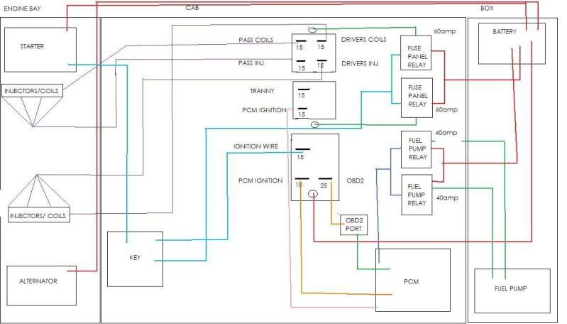 [/IMG]
[IMG]
[/IMG]