
'70 Nova LY6/TH400 6.0VVT
 09-06-2016, 02:43 PM
#1081

Thanks for the referal! I have ordered lots of stuff through Mouser which has high shipping fees and Waytek, which has high minimum quantities. I definitely need another source!
I thought carefully about where and how to breach my firewall to pass wiring. I really liked the idea of a Metripak or MIL-spec bulkhead connector, but with much of my firewall space consumed by the AC suitcase and ignition coils, I had limited locations for putting such a thing. Ultimately I decided to use a watertight passthrough grommet and a set of unsealled Metripak connectors so I could pass each connector through a hole, limiting the required hole size. This allowed me to utilize an existing hole just above the original firewall bulkhead connector. I just had to open it up, which I accomplished with a step bit. I had limited space without removing the brake booster, so I turned the step bit with a wrench and used thumb pressure.

With the hole prepped, I passed 15 wires through an Essentra IP67 EPDM sealing grommet.

Next I added Metripack connectors. I selected these specific connectors because they are very compact.

I used a 2, 6, and 8 terminal connectors. The 2 terminal will have wires going back to the trunk for the fuel pump relay and power from the master disconnect to the power on relay. The 6 terminal connector is for the DBW throttle pedal. The 8 terminal has the OBD GMLAN connections, battery power, ground, key on, MIL, and tachometer (with one terminal spare). These just barely fit through the 7/8" hole on the firewall, passing the largest connector first.

With the pass through harness done, I started on the first sub harness to the DBW throttle pedal. There is a subtle difference between the connections on a truck DBW pedal and the C6 Corvette pedal that I'm using, specifically that the D and F pins on the pedal itself are switched, so in order to use the C6 pedal, I had to swap these pins on the pedal connector. In the photo immediately below, the wires are brown and white/blk and they are positioned for the truck pedal

In the next photo, I have switched the brown and white/blk wires so they will connect to the proper terminals on the C6 pedal and I've added the 6pin mating connector to go to the firewall passthrough harness.

I also made up a similar sub-harness for the OBD2 connector, although I did not take a photo. The OBD2 pinout for the E38 ECM is as follows:
Pins 1,2,&3: Not Used
Pin 4: (BLACK) Ground
Pin 5: (BLACK/WHITE) Ground
Pin 6: (TAN/BLACK) GM High Speed LAN Serial Data Bus +, ECM X1 Pin 28
Pins 7 thru 13: Not Used
Pin 14: (TAN) GM High Speed LAN Serial Data Bus -, ECM X1 pin 27
Pin 15: Not Used
Pin 16: (RED/WHITE) Battery Positive Voltage
I should have the remainder of the wiring done pretty soon.
I thought carefully about where and how to breach my firewall to pass wiring. I really liked the idea of a Metripak or MIL-spec bulkhead connector, but with much of my firewall space consumed by the AC suitcase and ignition coils, I had limited locations for putting such a thing. Ultimately I decided to use a watertight passthrough grommet and a set of unsealled Metripak connectors so I could pass each connector through a hole, limiting the required hole size. This allowed me to utilize an existing hole just above the original firewall bulkhead connector. I just had to open it up, which I accomplished with a step bit. I had limited space without removing the brake booster, so I turned the step bit with a wrench and used thumb pressure.
With the hole prepped, I passed 15 wires through an Essentra IP67 EPDM sealing grommet.
Next I added Metripack connectors. I selected these specific connectors because they are very compact.
I used a 2, 6, and 8 terminal connectors. The 2 terminal will have wires going back to the trunk for the fuel pump relay and power from the master disconnect to the power on relay. The 6 terminal connector is for the DBW throttle pedal. The 8 terminal has the OBD GMLAN connections, battery power, ground, key on, MIL, and tachometer (with one terminal spare). These just barely fit through the 7/8" hole on the firewall, passing the largest connector first.
With the pass through harness done, I started on the first sub harness to the DBW throttle pedal. There is a subtle difference between the connections on a truck DBW pedal and the C6 Corvette pedal that I'm using, specifically that the D and F pins on the pedal itself are switched, so in order to use the C6 pedal, I had to swap these pins on the pedal connector. In the photo immediately below, the wires are brown and white/blk and they are positioned for the truck pedal
In the next photo, I have switched the brown and white/blk wires so they will connect to the proper terminals on the C6 pedal and I've added the 6pin mating connector to go to the firewall passthrough harness.
I also made up a similar sub-harness for the OBD2 connector, although I did not take a photo. The OBD2 pinout for the E38 ECM is as follows:
Pins 1,2,&3: Not Used
Pin 4: (BLACK) Ground
Pin 5: (BLACK/WHITE) Ground
Pin 6: (TAN/BLACK) GM High Speed LAN Serial Data Bus +, ECM X1 Pin 28
Pins 7 thru 13: Not Used
Pin 14: (TAN) GM High Speed LAN Serial Data Bus -, ECM X1 pin 27
Pin 15: Not Used
Pin 16: (RED/WHITE) Battery Positive Voltage
I should have the remainder of the wiring done pretty soon.
 10-24-2016, 11:04 AM
#1082
I picked up a Ford inertia switch for the fuel pump. I've been involving my son as much as I can lately, so perhaps it's best if I let him explain how it works. Here is a video: http://cjnn.xtremefabricator.com/ima...rtiaswitch.mp4
Below is a photo of the switch itself. It has a reset button in case I get in a fender bender. Playing around with this thing, it seems to react in all directions except "up" - i.e. if you tap hard from the sides or top, it will open the switch, but if you tap from the bottom it will not. This may be by design to prevent the switch from going off when you hit a hard pothole. Otherwise it should kill power to the fuel pump if hit from the side or if I landed on my roof.

I mounted the inertia switch on a support panel in the trunk, next to a Zettler 50amp relay and MTA Maxi fuse holder. One of my favorite "tools" I recently picked up is this Fastcap long nose pattern marker, which has a long, skinny tip for deep/long hole transfers. It was especially useful here for locating a mounting hole, because the panel is not flat and there was a sizable gap that I needed to bridge with a spacer. I used steel ribbed rivet nuts for mounting everything.


Everything is tucked between the battery box and the tail panel, but I have just enough room for my hands to change the fuse or reset the inertia switch.
The wiring is setup as follows: the ECM supplies low current +12v to the inertia switch when commanding fuel pump on. The inertia switch then passes that low current +12v to the relay. The relay switches a high current +12v feed from a 30amp Maxi fuse to the fuel pump, over 10awg GXL wires. If the inertia switch trips, the relay will de-energize, stopping the fuel pump.
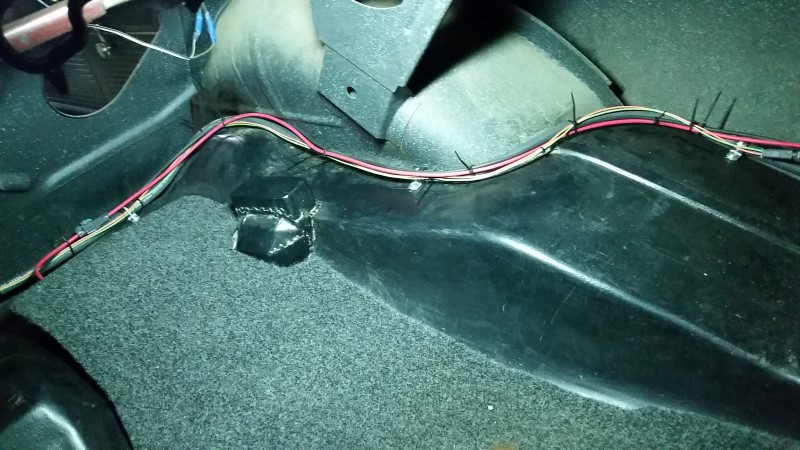
Below are some random photos of wire runs in the trunk. These are just zip tied in place for now; I will add loom after the car is running. The fuel pump wires feed through an Essentra IP67 (watertight) grommet in the trunk. I added a Metripack 280 connector so it can be disconnected for service. It meets up with a pair of 18awg wires running from the front of the car along the sill plate: one for the ECM fuel pump signal and the other to power the master shutoff relay from isolated power on the "4 pole" battery disconnect. That pair of wires has a Metripack 150 connnector so it too can be disconnected for service. I am trying to think ahead to eventually needing to strip the car down for paint.

Below is a photo of the switch itself. It has a reset button in case I get in a fender bender. Playing around with this thing, it seems to react in all directions except "up" - i.e. if you tap hard from the sides or top, it will open the switch, but if you tap from the bottom it will not. This may be by design to prevent the switch from going off when you hit a hard pothole. Otherwise it should kill power to the fuel pump if hit from the side or if I landed on my roof.
I mounted the inertia switch on a support panel in the trunk, next to a Zettler 50amp relay and MTA Maxi fuse holder. One of my favorite "tools" I recently picked up is this Fastcap long nose pattern marker, which has a long, skinny tip for deep/long hole transfers. It was especially useful here for locating a mounting hole, because the panel is not flat and there was a sizable gap that I needed to bridge with a spacer. I used steel ribbed rivet nuts for mounting everything.
Everything is tucked between the battery box and the tail panel, but I have just enough room for my hands to change the fuse or reset the inertia switch.
The wiring is setup as follows: the ECM supplies low current +12v to the inertia switch when commanding fuel pump on. The inertia switch then passes that low current +12v to the relay. The relay switches a high current +12v feed from a 30amp Maxi fuse to the fuel pump, over 10awg GXL wires. If the inertia switch trips, the relay will de-energize, stopping the fuel pump.
Below are some random photos of wire runs in the trunk. These are just zip tied in place for now; I will add loom after the car is running. The fuel pump wires feed through an Essentra IP67 (watertight) grommet in the trunk. I added a Metripack 280 connector so it can be disconnected for service. It meets up with a pair of 18awg wires running from the front of the car along the sill plate: one for the ECM fuel pump signal and the other to power the master shutoff relay from isolated power on the "4 pole" battery disconnect. That pair of wires has a Metripack 150 connnector so it too can be disconnected for service. I am trying to think ahead to eventually needing to strip the car down for paint.
Last edited by -TheBandit-; 10-24-2016 at 11:11 AM.
10-24-2016, 11:14 AM
#1083

Its great seeing your son wanting to be involved. Good idea on FORD inertia switch. I bet we see that become more common.
Thanks for sharing.
Thanks for sharing.
10-24-2016, 11:27 AM
#1085
10-24-2016, 11:36 AM
#1086
I don't know all the models and years that switch came on, but it was used prolifically by Ford from around 1990 through 2004. The eBay listing I bought it from lists compatible vehicles as 1990 through 2004 for Thunderbird, Bronco, Escort, F-150, Taurus, Explorer, Ranger, Crown Victoria, Mustang, Expedition, and Focus. They were probably also used on sister company vehicles like Mazda, Mercury and Lincoln.
As far as the gs required to trip the switch, I have come across no data or specifications on that, but given there are Mustangs with these installed, you could probably do a quick search to see if anyone modifying Mustangs has had problems. I suspect boost or braking would not trip it, but if you want to find out you could simply mount one on you car without wiring it and see if it ever trips.
You can trip it, as my son demonstrated, by whacking it against your hand or dropping on a hard surface, but both of these have some pretty high Gs compared to what your car is going to accomplish outside of a wreck.
11-02-2016, 01:29 PM
#1088
Next I needed a bracket to mount my jump start post. I had an old aluminum collet organizer in my stash which had the right hole size, so I cut it up with the porta-band (I wish I had a "real" bandsaw), bent it in the vise, and drilled a couple mounting holes.


I mounted it in front of the air cleaner on the radiator support using a pair of rivet nuts and stainless cap screws. I may later attach a small sheet of plastic around this to prevent accidental grounding. I added this jump start post, because the battery box is screwed shut and there isn't a good place to jump from otherwise. Sometimes I think I'm the only person in the world that carries jumper cables - I find myself helping neighbors or random people stranded in parking lots at least a few times a year.
After that, I decided it was time to take a break from wiring and knock out some hose connections here and there. First was the brake booster. The LSx intake manifolds have a large barb on the back that accepts 1/2" hose, but the vacuum check valve on my booster accepts 3/8". I scoured the autoparts store looking for an alternate check valve that would accept larger hose, but I could not find one, so I picked up a 3/8" x 1/2" brass elbow, painted it black, and stuck it here. The elbow helps a bit with routing the line anyway.

Next I needed a way to get fresh air into the crankcase for the PCV system. The OEM and many aftermarket valve covers include a baffled 3/8" barb connection for this purpose, but the GMPP valve covers I'm using do not. Rather than welding something on, I figured I could use the standard breather hole, but I had no luck finding a simple pass-through breather with a 3/8" connection - everything I came across included a PCV valve. So I found one suitable for taking apart. It's a Cal Custom CAL-188489 aluminum unit, which had a snap ring to retain what looks like your basic parts-store PCV valve inside of a fancier aluminum housing. I gutted it and popped it into the valve cover.


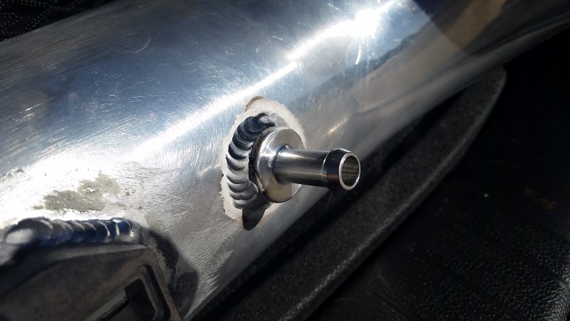
The fresh air side of the PCV system needs to connect to filtered, metered air (otherwise it will behave like a vacuum leak). So I picked up a weld in aluminum barb from eBay seller "sweetperformance" located in nearby Placentia, CA.
I also picked up a 1/8" NPT weld in bung for my radiator, which I will use for the steam line coming off the cylinder heads. It is welded in at a higher location than the heads, which should help burp air from the system.

I did not do the welding on either of these fittings, because I don't have a TIG welder. I just drilled the holes with a step bit and took them to the local shop Bones Fabrication.
I finally painted the fan shroud and installed the fan. I did not adequately protect the raw sheetmetal from rust, but I was able to get most of it off using Evaporust (spray, let sit, scour, rinse, repeat). I gotta say I really love that stuff - it actually does work as advertised. I also added hose clamps everywhere as needed.

Below you can see the wiring going to the jump start post. The 1/0 line on the right is coming from the battery disconnect in the trunk. The 1/0 line on the left runs to the starter. The 4awg wire runs along the bottom/front of the radiator support to the main distribution post on the passenger side (which is incidentally where the alternator connects). At some point I need to punch a hole in here someplace for cold air to the filter.

One of the last items on the list was the transmission coolant lines. I hate doing anything transmission related because I am hoping to eventually ditch this TH400 for a proper grab-handle with a third pedal. Anyway, transmission fluid enters the integrated radiator/trans cooler through 3/8" Summit push-lock hose and a 1/4NPT to AN adapter. It then exits the top of the radiator and runs through a hardline to the bottom of a second auxiliary cooler at the front of the car. Finally it makes it sway back to the transmission through the same type of hose.


With the AC mounted low on the passenger side along with the starter cable and the waterpump inlet, there wasn't much room for transmission lines in the conventional location, so I opted to have them route along the outside of the frame, underneath the upper control arm.

An offroadfabnet forum member turned me on to these awesome snap-in plastic clamps available from McMaster Carr - they are perfect for this kind of thing! I will warn, however, that I had to reorder one size bigger than what they were advertised to fit. I think they are sized for hard tubing where it is okay for the plastic to clamp pretty hard, but it did not work for hose. So while my hose is 9/16" OD, I used clamps sized for 5/8-3/4" OD (McMaster P/N 7429K46).


Here is where the transmission lines connect to the TH400. I used 1/4" NPS (national pipe straight) to -6AN adapters. DO NOT use NPT (national pipe taper) for these - it will thread in and you can probably get it to seal, but it the taper stresses the housing and can lead to cracks.

Another item to note is that the TCI flexplate I am using required longer bolts that what I had for my SBC. The old SBC bolts were 7/16-20 x 3/4" long. I picked up some ARP 230-7303 7/16-20 x 1-1/4" long bolts to replace them.

Here are some walk-around photos of the near-finished product.


I have been going around testing circuits and so far things are mostly checking out. The starter cranks. The ECM turns on the MIL (check engine lamp) when IGN power is applied and it runs the fuel pump for a few seconds to prime as expected. The drive-by-wire throttle body responds to input from the accelerator pedal (which goes well with the simulated engine sounds I make "vroom vroom"). The power on relay clicks on and off when IGN is applied, providing juice to the injectors and coils as expected.
I attempted to connect an OBD2 reader, but found I have the CAN bus high and low wires reversed in the OBD2 connector (whoops), so I will need to swap those pins and hopefully it will work after that. Once I get that sorted out, I will start adding fluids and schedule the tuner to come put a start up tune on it.
I mounted it in front of the air cleaner on the radiator support using a pair of rivet nuts and stainless cap screws. I may later attach a small sheet of plastic around this to prevent accidental grounding. I added this jump start post, because the battery box is screwed shut and there isn't a good place to jump from otherwise. Sometimes I think I'm the only person in the world that carries jumper cables - I find myself helping neighbors or random people stranded in parking lots at least a few times a year.
After that, I decided it was time to take a break from wiring and knock out some hose connections here and there. First was the brake booster. The LSx intake manifolds have a large barb on the back that accepts 1/2" hose, but the vacuum check valve on my booster accepts 3/8". I scoured the autoparts store looking for an alternate check valve that would accept larger hose, but I could not find one, so I picked up a 3/8" x 1/2" brass elbow, painted it black, and stuck it here. The elbow helps a bit with routing the line anyway.
Next I needed a way to get fresh air into the crankcase for the PCV system. The OEM and many aftermarket valve covers include a baffled 3/8" barb connection for this purpose, but the GMPP valve covers I'm using do not. Rather than welding something on, I figured I could use the standard breather hole, but I had no luck finding a simple pass-through breather with a 3/8" connection - everything I came across included a PCV valve. So I found one suitable for taking apart. It's a Cal Custom CAL-188489 aluminum unit, which had a snap ring to retain what looks like your basic parts-store PCV valve inside of a fancier aluminum housing. I gutted it and popped it into the valve cover.
The fresh air side of the PCV system needs to connect to filtered, metered air (otherwise it will behave like a vacuum leak). So I picked up a weld in aluminum barb from eBay seller "sweetperformance" located in nearby Placentia, CA.
I also picked up a 1/8" NPT weld in bung for my radiator, which I will use for the steam line coming off the cylinder heads. It is welded in at a higher location than the heads, which should help burp air from the system.
I did not do the welding on either of these fittings, because I don't have a TIG welder. I just drilled the holes with a step bit and took them to the local shop Bones Fabrication.
I finally painted the fan shroud and installed the fan. I did not adequately protect the raw sheetmetal from rust, but I was able to get most of it off using Evaporust (spray, let sit, scour, rinse, repeat). I gotta say I really love that stuff - it actually does work as advertised. I also added hose clamps everywhere as needed.
Below you can see the wiring going to the jump start post. The 1/0 line on the right is coming from the battery disconnect in the trunk. The 1/0 line on the left runs to the starter. The 4awg wire runs along the bottom/front of the radiator support to the main distribution post on the passenger side (which is incidentally where the alternator connects). At some point I need to punch a hole in here someplace for cold air to the filter.
One of the last items on the list was the transmission coolant lines. I hate doing anything transmission related because I am hoping to eventually ditch this TH400 for a proper grab-handle with a third pedal. Anyway, transmission fluid enters the integrated radiator/trans cooler through 3/8" Summit push-lock hose and a 1/4NPT to AN adapter. It then exits the top of the radiator and runs through a hardline to the bottom of a second auxiliary cooler at the front of the car. Finally it makes it sway back to the transmission through the same type of hose.
With the AC mounted low on the passenger side along with the starter cable and the waterpump inlet, there wasn't much room for transmission lines in the conventional location, so I opted to have them route along the outside of the frame, underneath the upper control arm.
An offroadfabnet forum member turned me on to these awesome snap-in plastic clamps available from McMaster Carr - they are perfect for this kind of thing! I will warn, however, that I had to reorder one size bigger than what they were advertised to fit. I think they are sized for hard tubing where it is okay for the plastic to clamp pretty hard, but it did not work for hose. So while my hose is 9/16" OD, I used clamps sized for 5/8-3/4" OD (McMaster P/N 7429K46).
Here is where the transmission lines connect to the TH400. I used 1/4" NPS (national pipe straight) to -6AN adapters. DO NOT use NPT (national pipe taper) for these - it will thread in and you can probably get it to seal, but it the taper stresses the housing and can lead to cracks.
Another item to note is that the TCI flexplate I am using required longer bolts that what I had for my SBC. The old SBC bolts were 7/16-20 x 3/4" long. I picked up some ARP 230-7303 7/16-20 x 1-1/4" long bolts to replace them.
Here are some walk-around photos of the near-finished product.
I have been going around testing circuits and so far things are mostly checking out. The starter cranks. The ECM turns on the MIL (check engine lamp) when IGN power is applied and it runs the fuel pump for a few seconds to prime as expected. The drive-by-wire throttle body responds to input from the accelerator pedal (which goes well with the simulated engine sounds I make "vroom vroom"). The power on relay clicks on and off when IGN is applied, providing juice to the injectors and coils as expected.
I attempted to connect an OBD2 reader, but found I have the CAN bus high and low wires reversed in the OBD2 connector (whoops), so I will need to swap those pins and hopefully it will work after that. Once I get that sorted out, I will start adding fluids and schedule the tuner to come put a start up tune on it.
 11-03-2016, 12:08 AM
#1090
Time to call the tuner!
Last edited by -TheBandit-; 11-03-2016 at 11:05 AM.
 11-04-2016, 01:27 AM
#1093
Spent a fair bit of time on the phone today with a local tuner in Agoura Hills - Alex at New Era Performance. I discussed all the changes that have been made, one by one, as you might imagine an over thinking engineer like myself would. He explained how he would manage the changes and was confident he can program the ECM on the bench with a good enough baseline calibration to start, idle, and drive safely to his shop for final dyno tuning. So tomorrow I will drop it off and hopefully I'll be posting a startup video next week.
11-04-2016, 02:23 AM
#1094
Such a nice looking eng. compartment !!!
11-08-2016, 09:05 AM
#1095
Thank you Jimbo! I am really happy with the valve covers and relocated coils. The engine compartment needs a bunch of cleaning 
The ECM came back from the tuner yesterday, so after playing domesticated family man for most of the evening and filling out my sample ballot for voting tomorrow, I got a late start on the Nova. First step was checking tightness on all the fuel connections - check. Next, I primed the fuel system by jumpering input to the the fuel pump relay. Using a loaner fuel pressure gage from the local autoparts store, I found fuel pressure at the shrader valve on the fuel rail came up to about 56psi. I bled the air out of the system and checked for leaks. Everything looked good.
Next, I hooked up my Wifi OBD scanner and fired up the Torque App on my phone. This combination is pretty cool - you can customize a "dash" on your phone/tablet, monitor any sensor you want in near real time, and check codes. I did have to load GM-specific PIDs in the Torque app so I could monitor oil pressure, but that was easy enough.
Everything checked out, sensors were giving expected values, and there were no codes. So at just about 10pm I invited my wife to the garage to spot leaks and I was off and cranking. Oil pressure came up right away, RPM registered around 100-150 during cranking, and it began to sputter/fire intermittently. For a moment (2-3seconds) it found a very brief idle and RPM spiked to around 700rpm, but alas it would not hold and returned to cranking and sputtering again.
For that brief 2-3 seconds when it seemed to be running, my wife and I got an audible sample of what this thing is going to sound like. With 3 inch Dynomax VT muffers, it was every bit as loud (at least in the confined space of my garage) as the old SBC with 2 chamber Flowmasters. The kid in me was thrilled, but my wife and I were both concerned about making so much noise after 10pm. My kids, the neighbor's kids, and a number of retirees in the neighborhood were surely sleeping. So after a few unsuccessful cranking attempts, we called it a night.
Before closing shop, I checked for codes. I got one and only one: P0315 Crankshaft Position System Variation Not Learned. From what I understand, that should not keep it from running, but will prevent it from detecting misfire. I assume the lack of other codes is a good sign.
I will give it another try when I have time today. If it does not want to run, I'll go back to the basics: check for spark and check for fuel. That little bit of rumble I got last night makes me think it could be as simple as air remaining in the fuel system, but we'll see.
11-08-2016, 08:48 PM
#1098
Success!
Turns out the pink and black wires needed to be switched on the MAF connector due to changing from the LY6 screen style MAF to an LS7 card style MAF. The computer was not getting a MAF signal as a result. I probably read about this at some point and forgot to make the change. Huge thanks to the tuner, Alex at New Era Performance in Agoura Hills. He normally does not do house calls, but he offered to come sort this out with me and we found the problem in mere minutes. I swapped the wires and it fired right up.
Still plenty of work left to make it a driver, but this is a welcome milestone!
 11-09-2016, 10:49 AM
#1100
Thanks guys!
Here's another video with more of a walk around.
What finally got me to this point, after years of dragging my feet, was distilling this project to a simple list of things to check off, ignoring anything that was not absolutely needed to get the engine started. Now I need to make the same sort of list with a goal of getting the car on it's own four feet. It's so hard not to get distracted - I am already consumed with ideas for the interior, cage, suspension, brakes, etc. But those things can all come as smaller projects down the road. For now I just need to make it roll