
C3 78' Corvette LS1/T-56 with Holset HX-55 Turbo build
 04-04-2013, 10:56 AM
#81
Launching!
Thread Starter
Join Date: Jul 2011
Location: Detroit, Michigan
Posts: 209
Likes: 0
Received 0 Likes
on
0 Posts
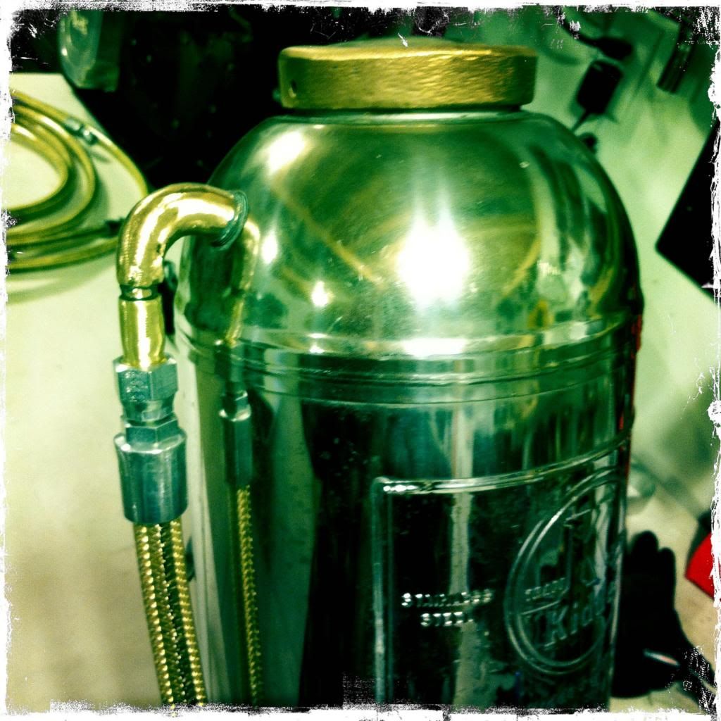
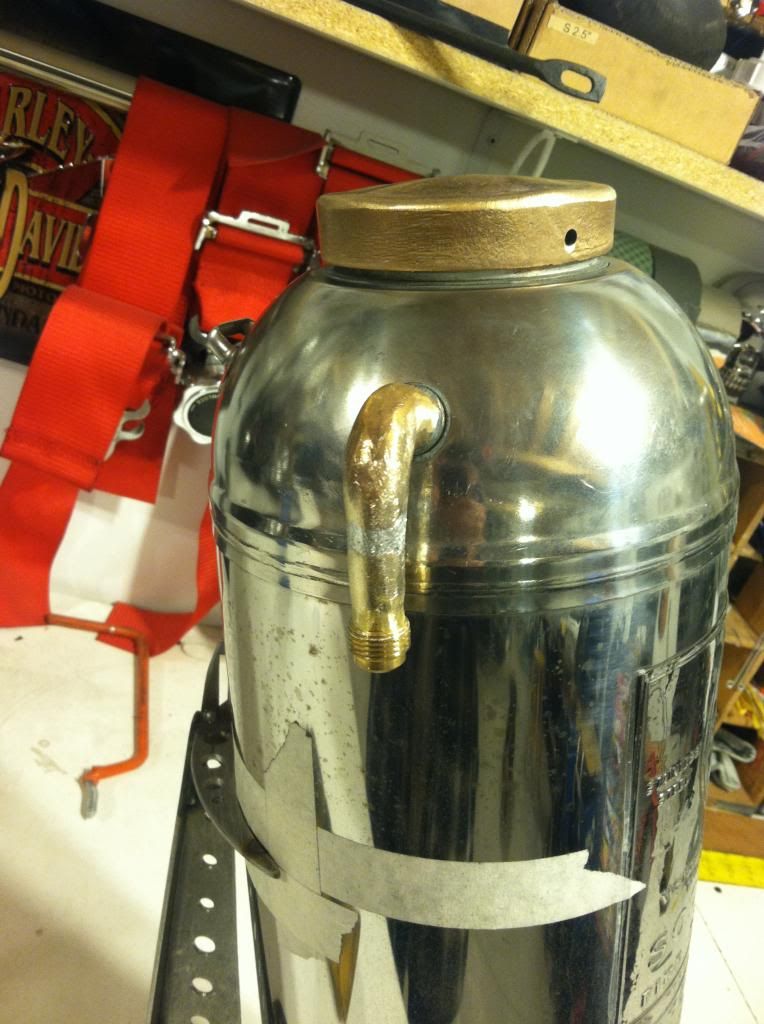
not much progress on the vette lately. Done some more work to the IP but nothing too substantial to show yet. For the water tank I used the existing hose barb that was on the fire extinguisher but had to make a fitting for the water line. I ended up pounding a fitting over the barb. I havnt tested it yet but I am pretty sure it is sealed nice and tite. I then smoothed it out some , but didnt care to make it perfect because I like the rough look on the copper, it matches the lid.
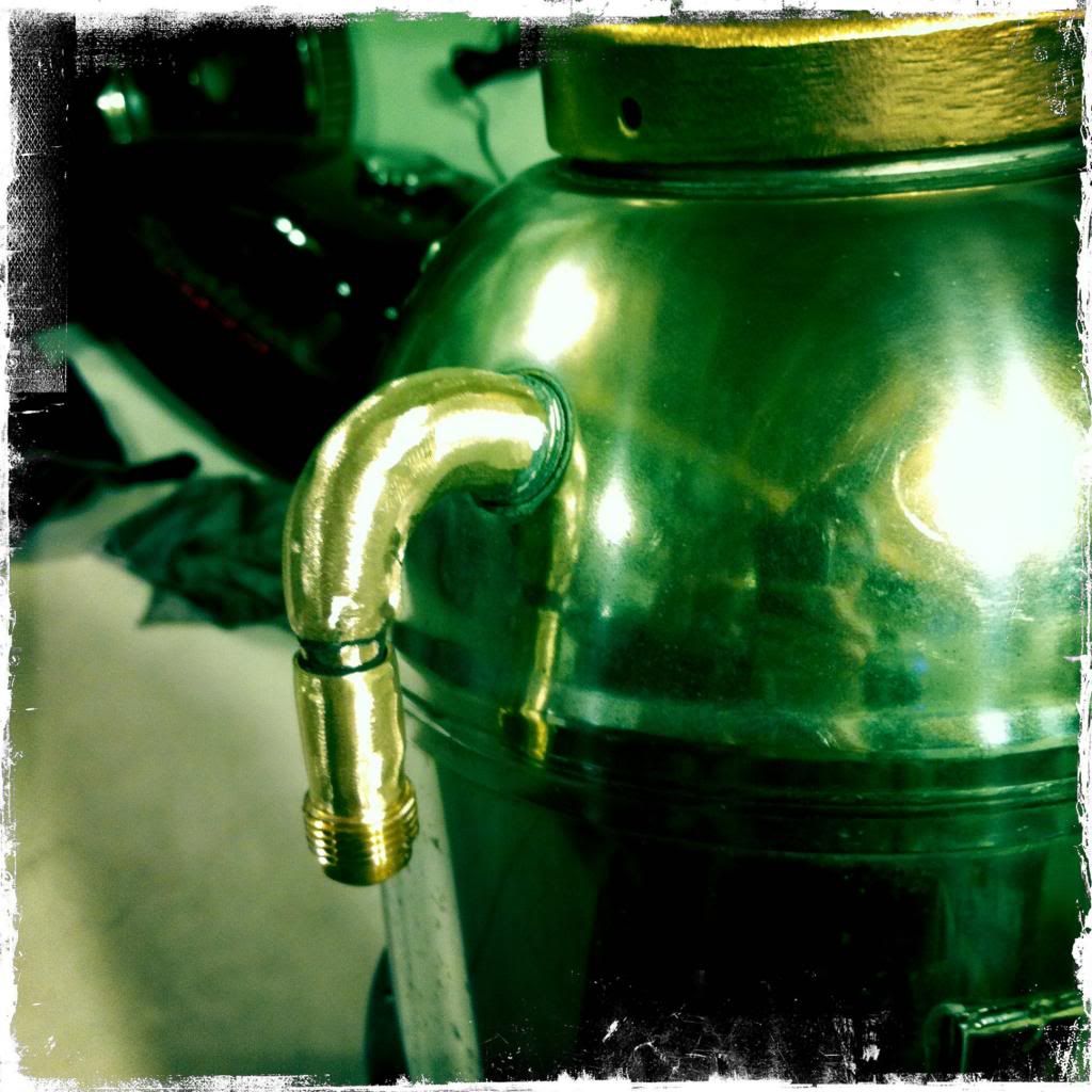
Had to share a picture of the hose off..... It looks pretty bad!!!! LOL
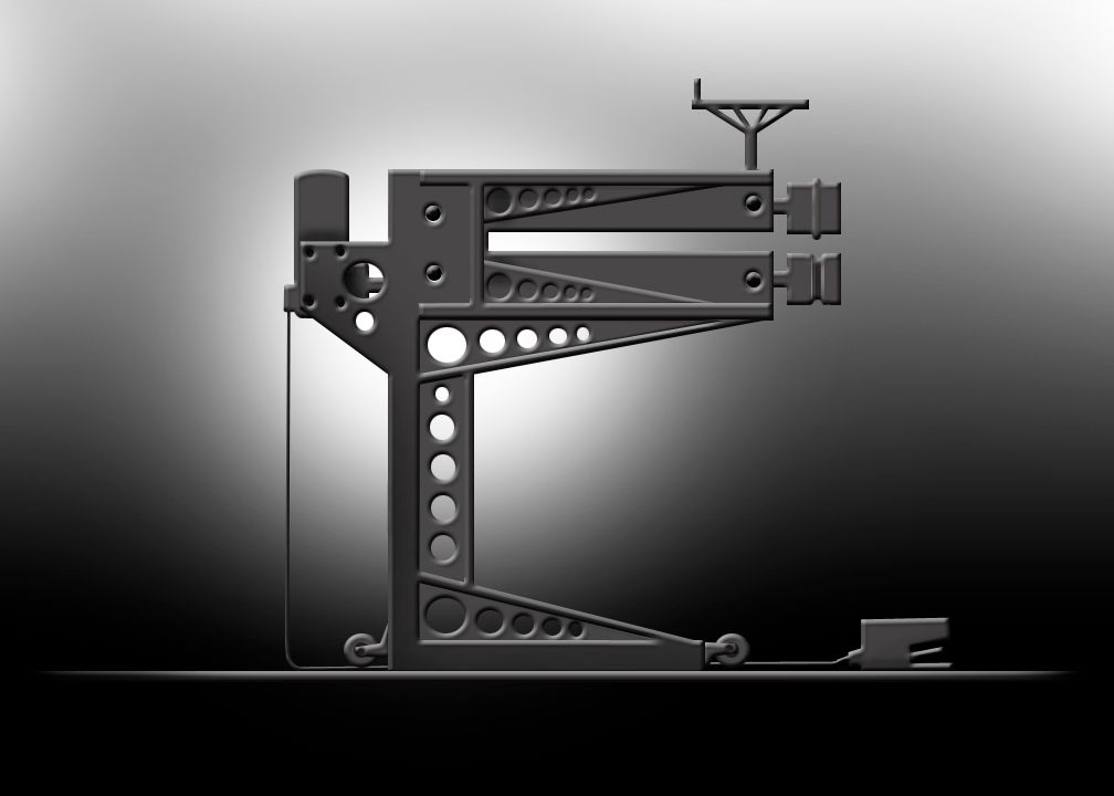
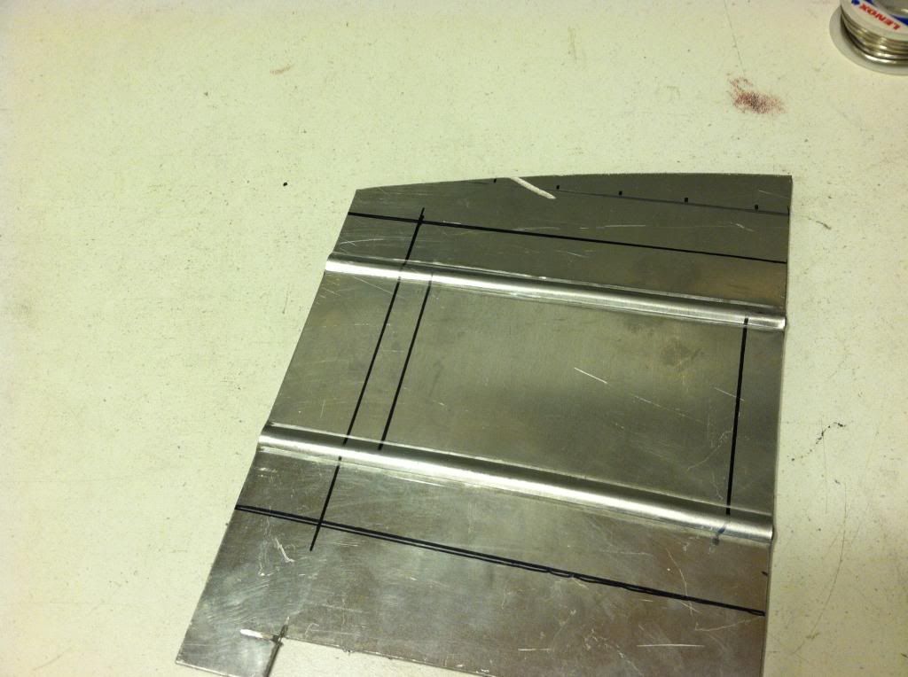
I also started making my new tool to help with the interior. Here is a quick design I did to help keep me on track. Should have it done in the next day or so.
Had to share a picture of the hose off..... It looks pretty bad!!!! LOL
I also started making my new tool to help with the interior. Here is a quick design I did to help keep me on track. Should have it done in the next day or so.
 04-16-2013, 01:09 PM
#82
Launching!
Thread Starter
Join Date: Jul 2011
Location: Detroit, Michigan
Posts: 209
Likes: 0
Received 0 Likes
on
0 Posts
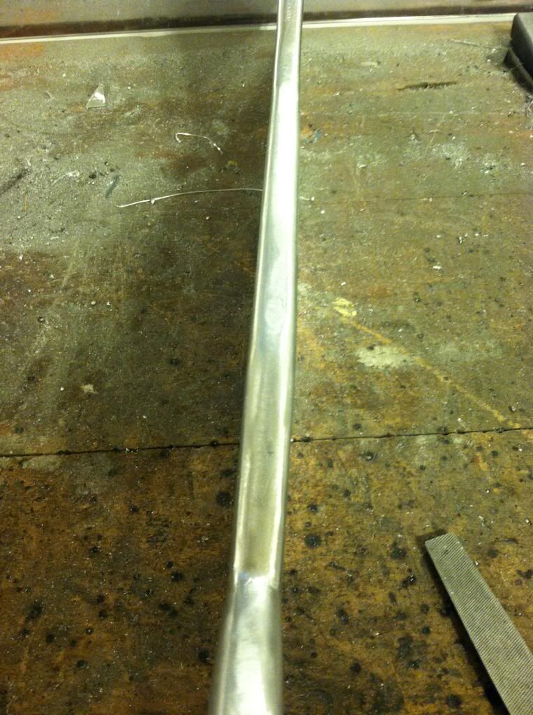
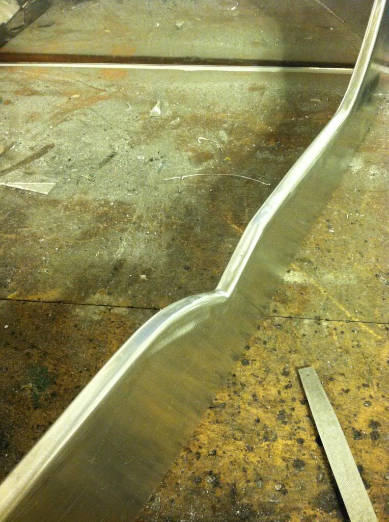
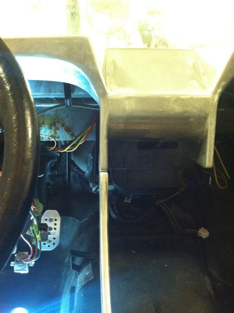
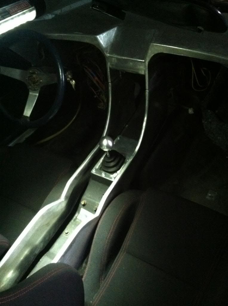
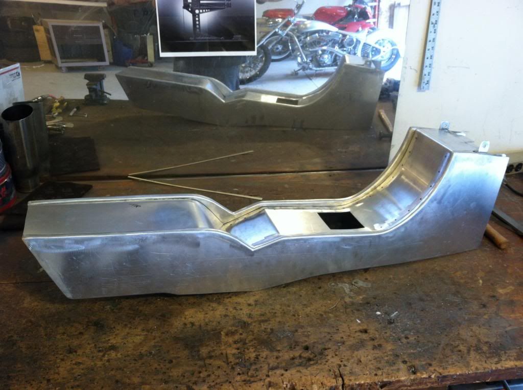
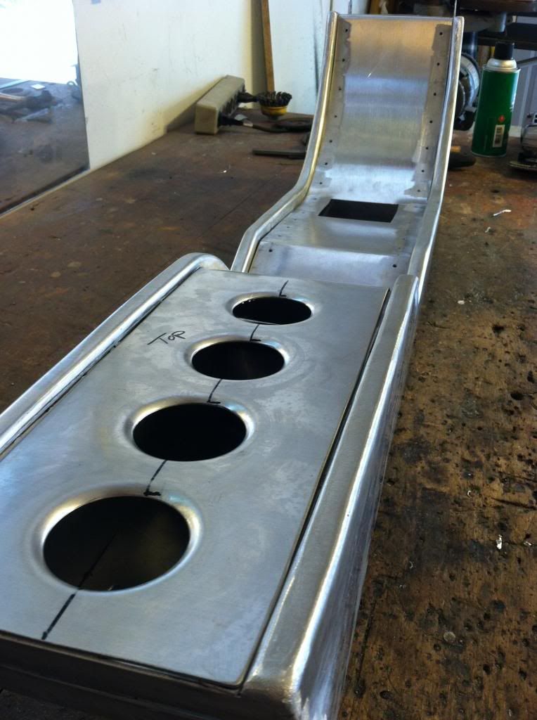
Slow but sure.... the IP top pad is now securely mounted with. It takes just 2 wing nuts to secure or unbolt it and it really solid. I have also made the center console side walls.
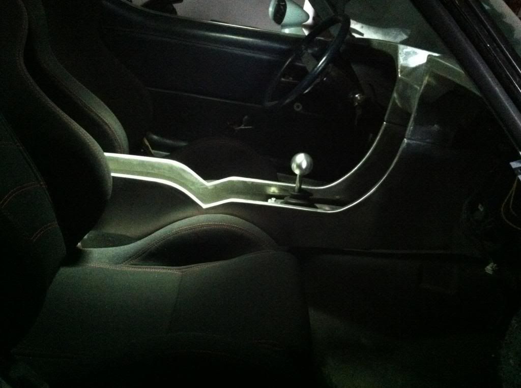
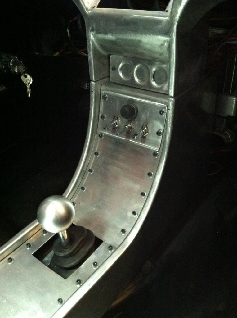
Here is a good view of the width of each wall. I am getting better at this aluminum welding and shaping stuff.
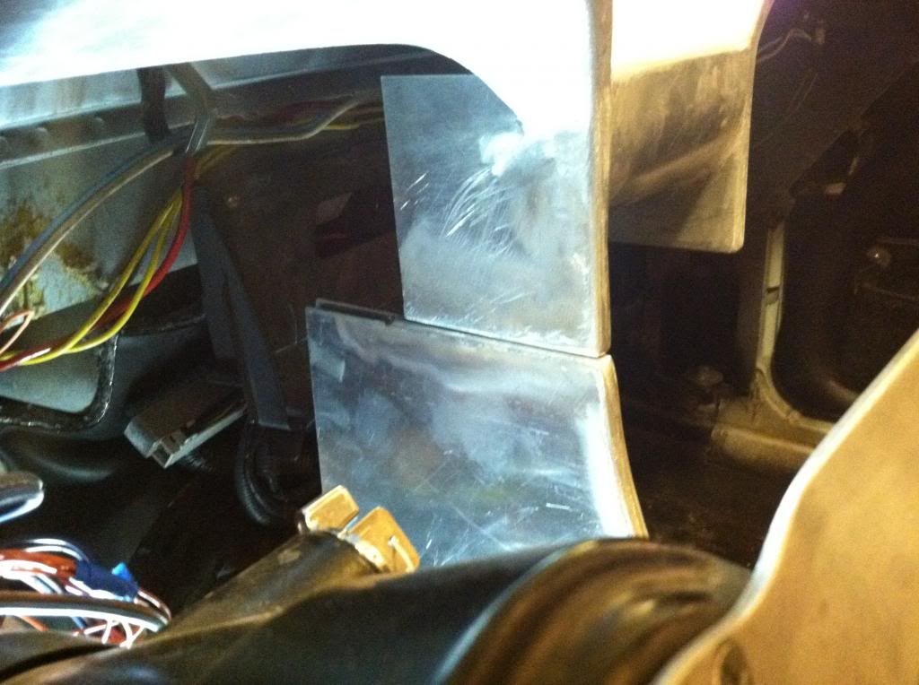
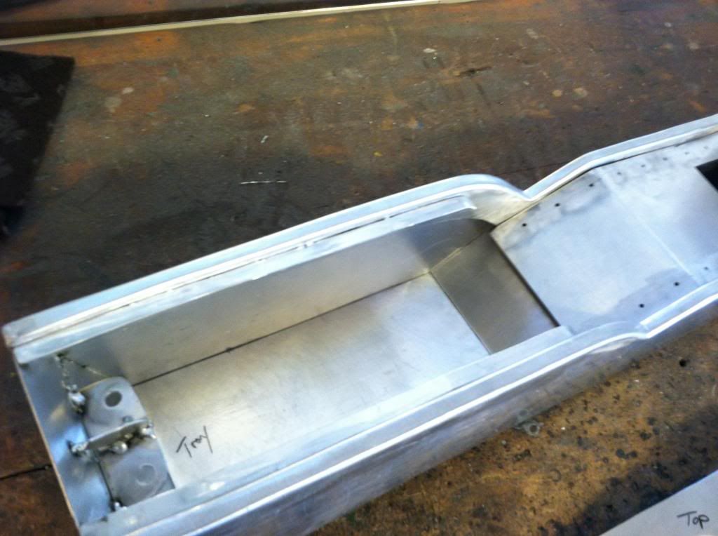
This picture shows the IP to center console interface. Not too bad for the first attempt and test fit. The centerconsole wall is just sitting there with no support. Once I figure out the fastner solutions I should have the alignment all sorted out. I'm planning on using wingnuts on all mounting points to make for quick and easy removal and instal.
I also brazed the connection between the fitting I pressed over the fire extinguisher barb to ensure the seal.


Here is a good view of the width of each wall. I am getting better at this aluminum welding and shaping stuff.


This picture shows the IP to center console interface. Not too bad for the first attempt and test fit. The centerconsole wall is just sitting there with no support. Once I figure out the fastner solutions I should have the alignment all sorted out. I'm planning on using wingnuts on all mounting points to make for quick and easy removal and instal.


I also brazed the connection between the fitting I pressed over the fire extinguisher barb to ensure the seal.

Last edited by User-c3; 04-16-2013 at 01:15 PM.
04-24-2013, 12:45 PM
#83
Launching!
Thread Starter
Join Date: Jul 2011
Location: Detroit, Michigan
Posts: 209
Likes: 0
Received 0 Likes
on
0 Posts
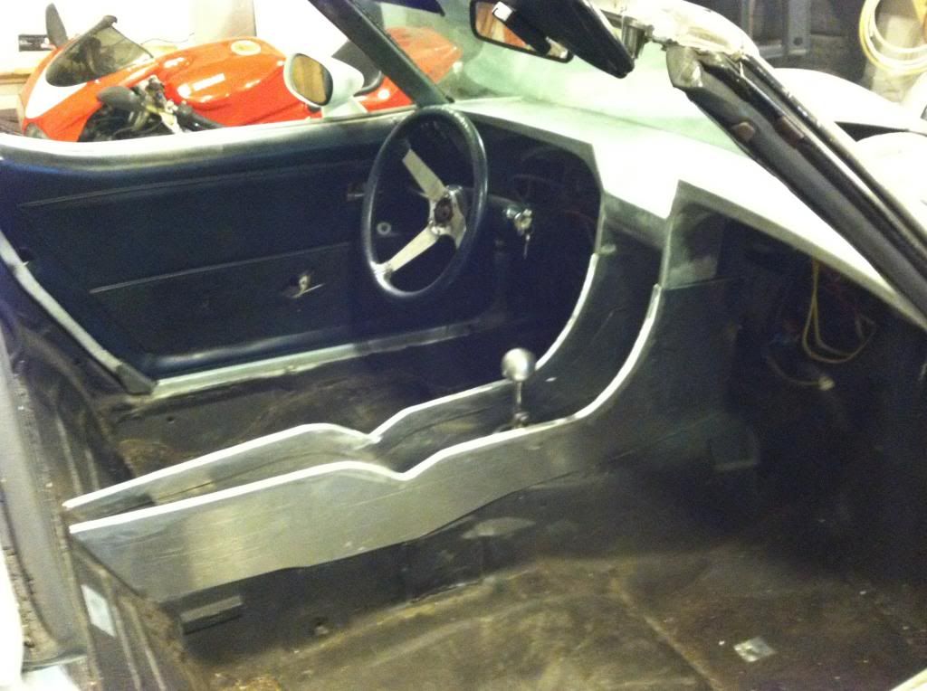
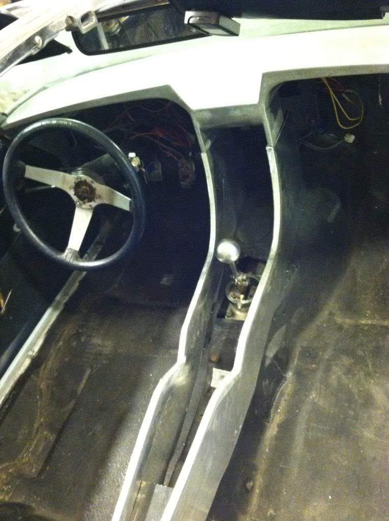
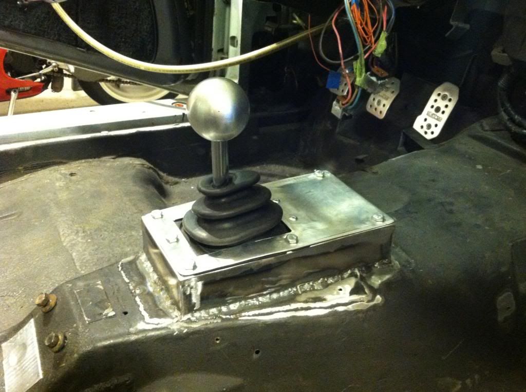
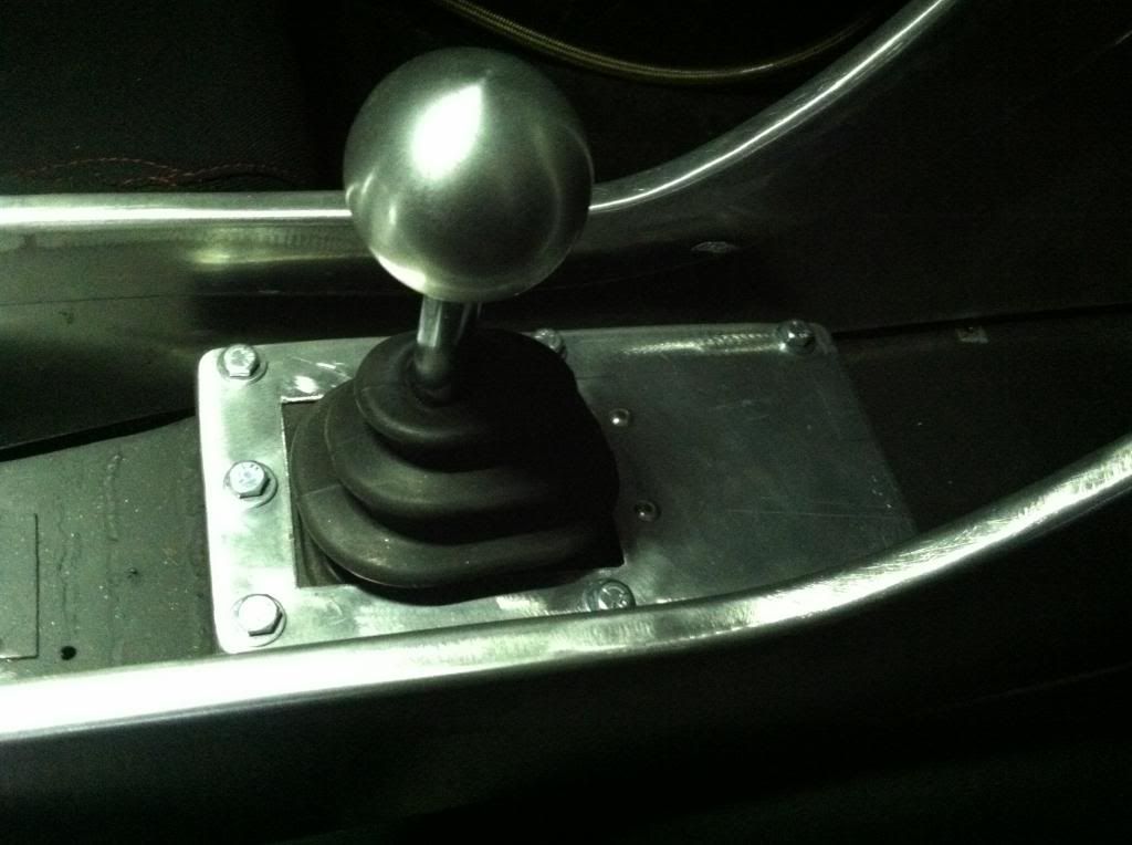
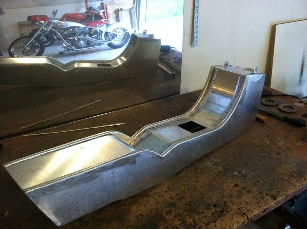
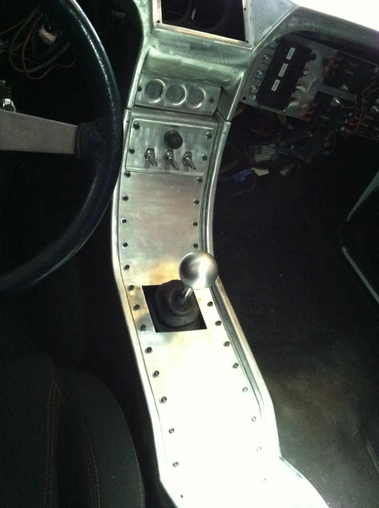
Work seems to progress so slow. I have been working out the mounting locations for the dash and console, and also started on rewiring. I made a new box around the shifter to still allow for easy engine/trans removal but seal it up and be nice and clean at the same time.
I am still not happy with the sharp points on the top of the IP. I need to round them out to match the curve under them. I will get to that later on when I have the entire picture more complete.
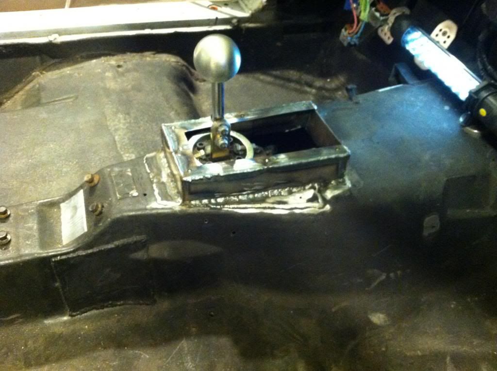
I am still not happy with the sharp points on the top of the IP. I need to round them out to match the curve under them. I will get to that later on when I have the entire picture more complete.


Last edited by User-c3; 04-24-2013 at 01:34 PM.
 05-06-2013, 09:04 AM
#86
Launching!
Thread Starter
Join Date: Jul 2011
Location: Detroit, Michigan
Posts: 209
Likes: 0
Received 0 Likes
on
0 Posts
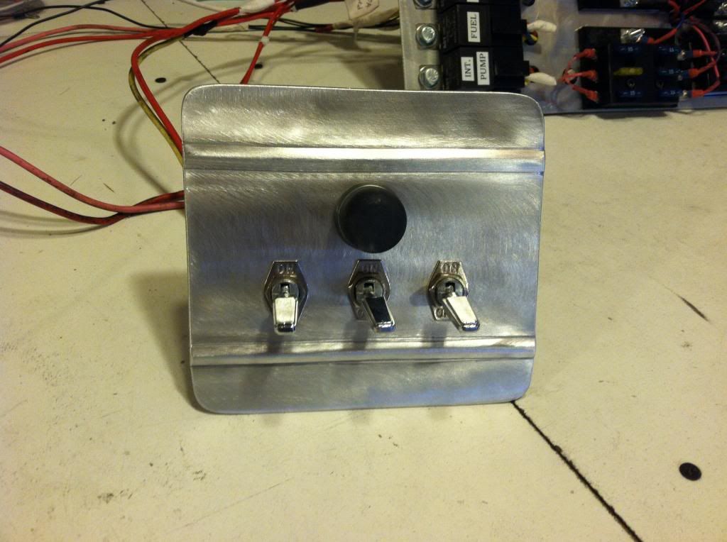
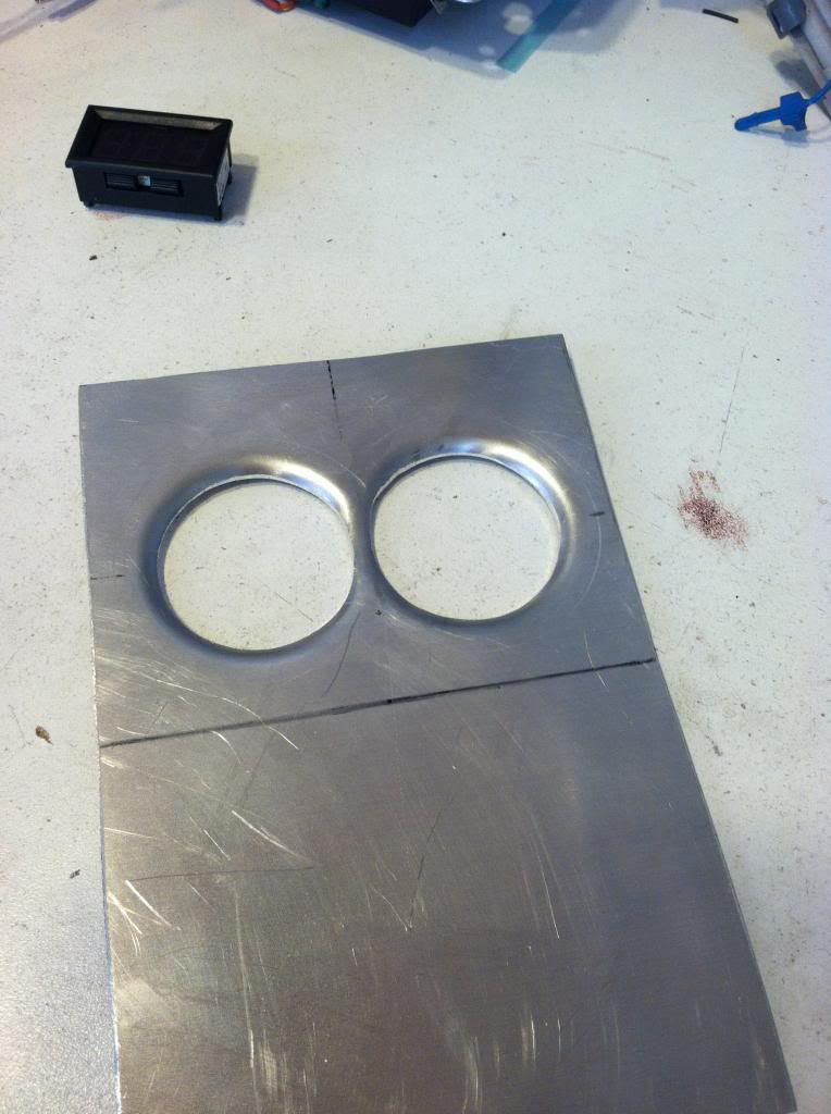
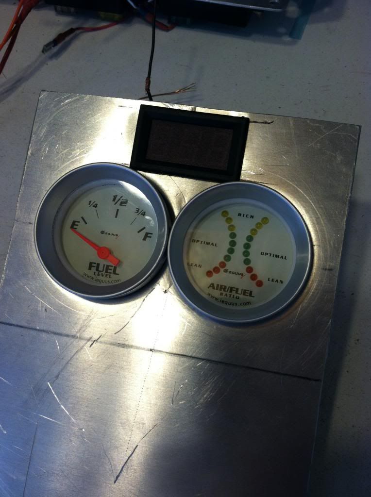
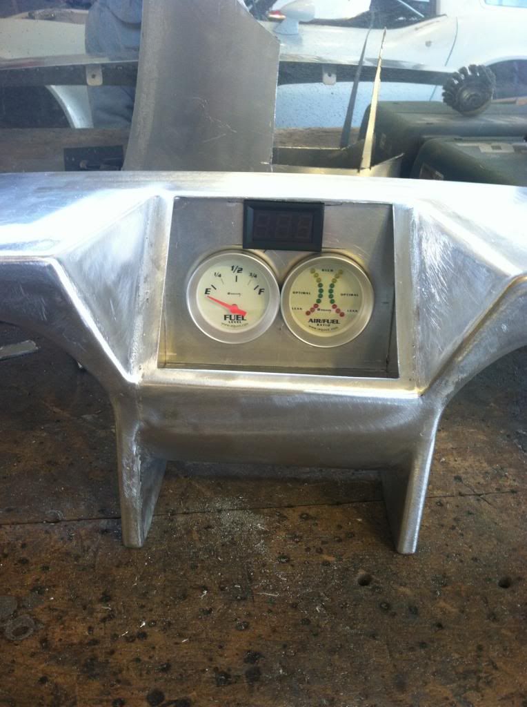
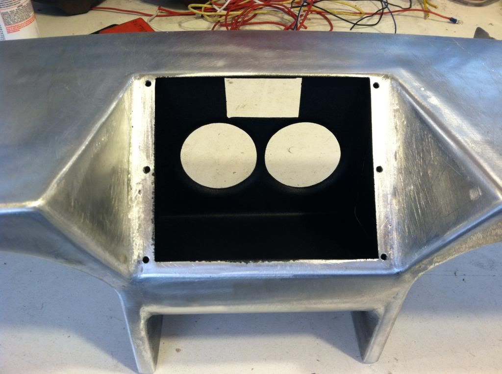
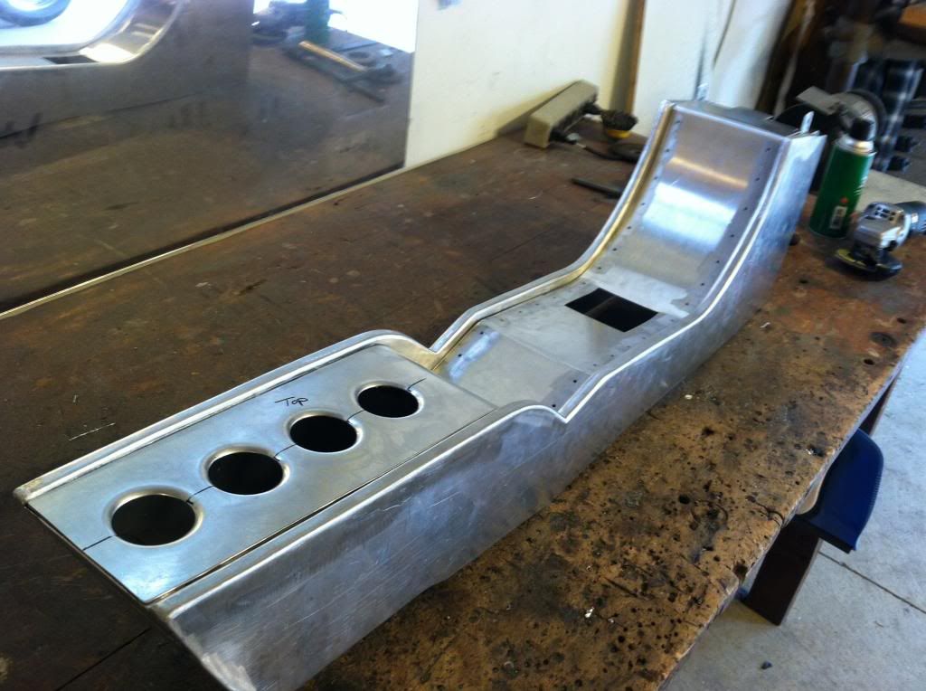
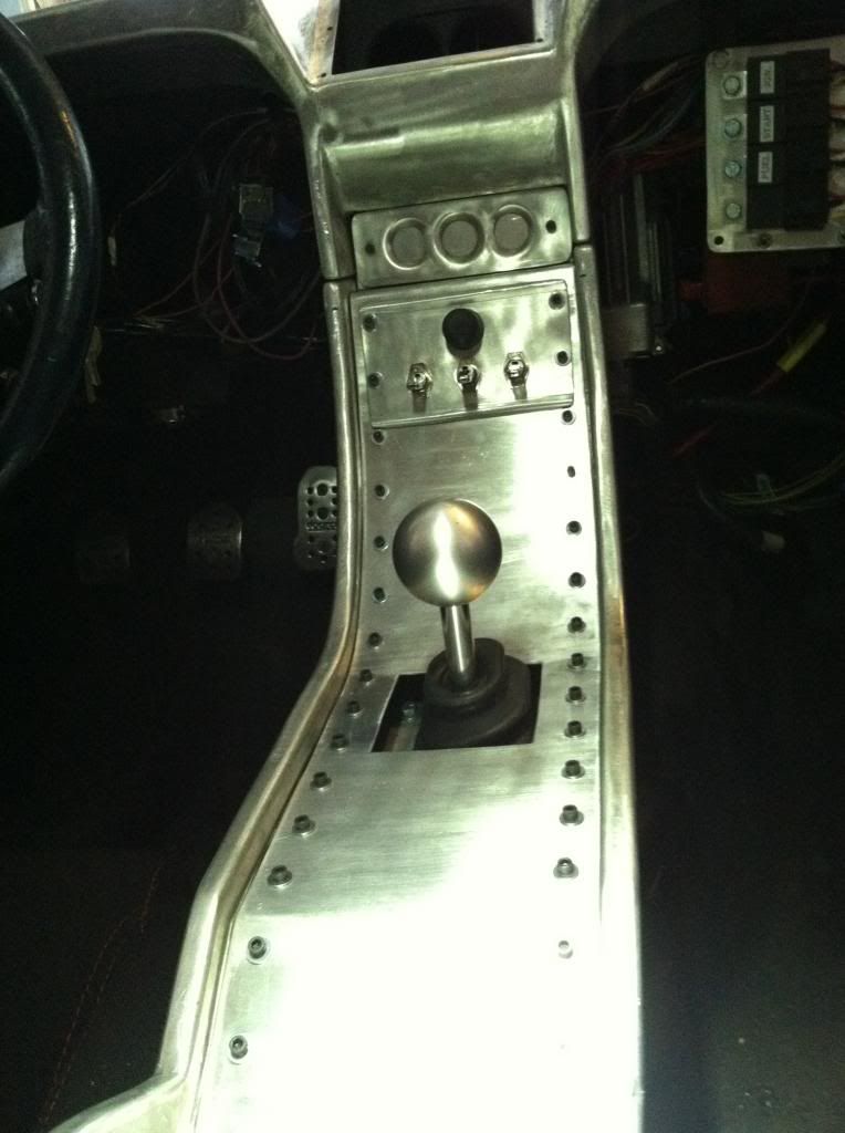
Made a switch panel, for the power, ignition, and fans. I have the intercooler pump wired into the fan switch so they turn on at the same time. I used my new bead roller I made. This was my first time using a bead roller, and using this one that I made, the test piece was my panel, so it worked pretty well. I also made the opening in the IP for the gauges I will run inside of it, and also cut the plexy cover to go over it. Painted the inside black so when the plexy is tinted you wont be able to see anything inside except the gauges when they light up.
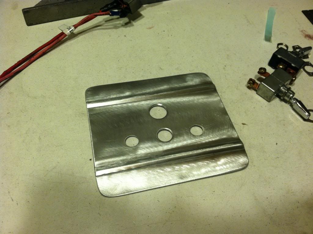
I also used my HF hydraulic knockout punch tool. Works surprisingly very well. I then used my new dimple dies that also hook up to the hydraulic ram to dimple the piece. Didnt really need to use the dimple dies but they gave me a bit more room for the gauge to sit in and I wanted to try them.


I also used my HF hydraulic knockout punch tool. Works surprisingly very well. I then used my new dimple dies that also hook up to the hydraulic ram to dimple the piece. Didnt really need to use the dimple dies but they gave me a bit more room for the gauge to sit in and I wanted to try them.


 06-03-2013, 11:49 AM
#87
Launching!
Thread Starter
Join Date: Jul 2011
Location: Detroit, Michigan
Posts: 209
Likes: 0
Received 0 Likes
on
0 Posts
some updates:
The car is coming back from the tuner this week, unfortunatly it is not complete and driving back under its own power. I am having some voltage issues dropping a full volt which is interupting the tuning and injectors. I am also having some issues with building boost. I spent a good deal of the day at the shop on thursday working on the car and bench testing the wastegate and some other things, but thinking the intercooler may be the culprit.
on another note since the car has been out of the garage I have been getting a bit of work done on the center console.
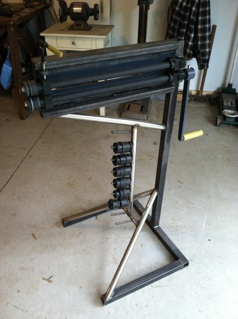
I also never posted pictures of the bead roller I made so here ya go.
the quick design I had done
here it is, not totally done but functional. I still need to instal the motor and paint it. Started out as the Harbor Freight unit.
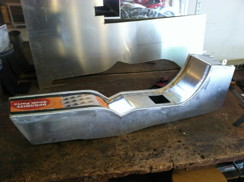
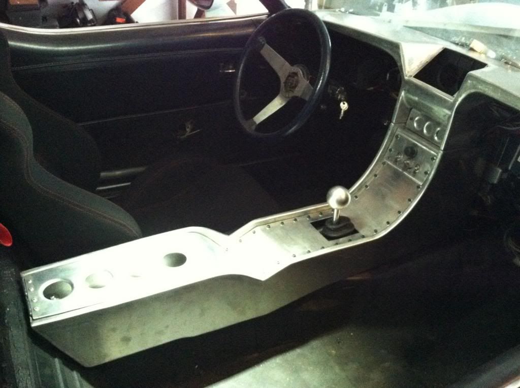
I made the main center surface with the shifter cutout. all the holes along the perimeter are mounting. I will be using allen bolts to give it the look I am going for. Here you can see the template for the armrest piece. I use some cardboard to get a template and then tape off the edges to get the exact shape and measurements I want.
armrest piece cut and bent into shape.
hole punched and dimpled the armrest. there will be a plate under the dimples and the armrest will be wrapped exposing bare aluminum openings.
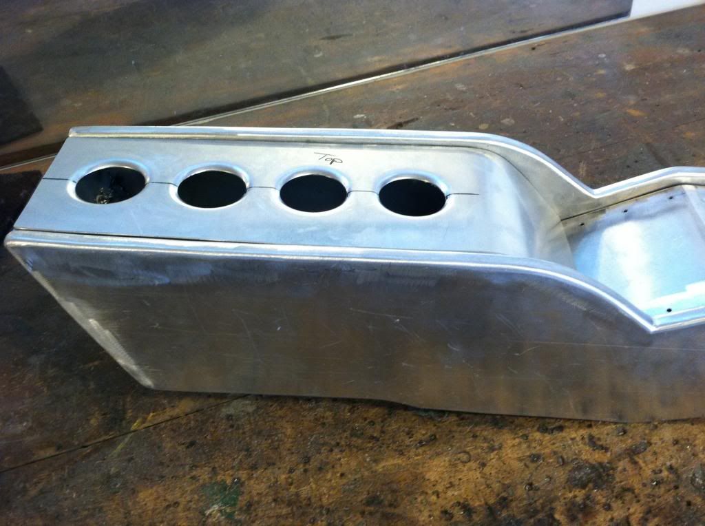
and I now have usable center consol storage, something the c's always lacked. You can see in this photo the rails for the lid, I did the same thing for the center stack up all the way up which the allen bolts will screw in to.
The car is coming back from the tuner this week, unfortunatly it is not complete and driving back under its own power. I am having some voltage issues dropping a full volt which is interupting the tuning and injectors. I am also having some issues with building boost. I spent a good deal of the day at the shop on thursday working on the car and bench testing the wastegate and some other things, but thinking the intercooler may be the culprit.
on another note since the car has been out of the garage I have been getting a bit of work done on the center console.
I also never posted pictures of the bead roller I made so here ya go.
the quick design I had done

here it is, not totally done but functional. I still need to instal the motor and paint it. Started out as the Harbor Freight unit.

I made the main center surface with the shifter cutout. all the holes along the perimeter are mounting. I will be using allen bolts to give it the look I am going for. Here you can see the template for the armrest piece. I use some cardboard to get a template and then tape off the edges to get the exact shape and measurements I want.

armrest piece cut and bent into shape.


hole punched and dimpled the armrest. there will be a plate under the dimples and the armrest will be wrapped exposing bare aluminum openings.


and I now have usable center consol storage, something the c's always lacked. You can see in this photo the rails for the lid, I did the same thing for the center stack up all the way up which the allen bolts will screw in to.
 06-24-2013, 11:53 AM
#88
Launching!
Thread Starter
Join Date: Jul 2011
Location: Detroit, Michigan
Posts: 209
Likes: 0
Received 0 Likes
on
0 Posts
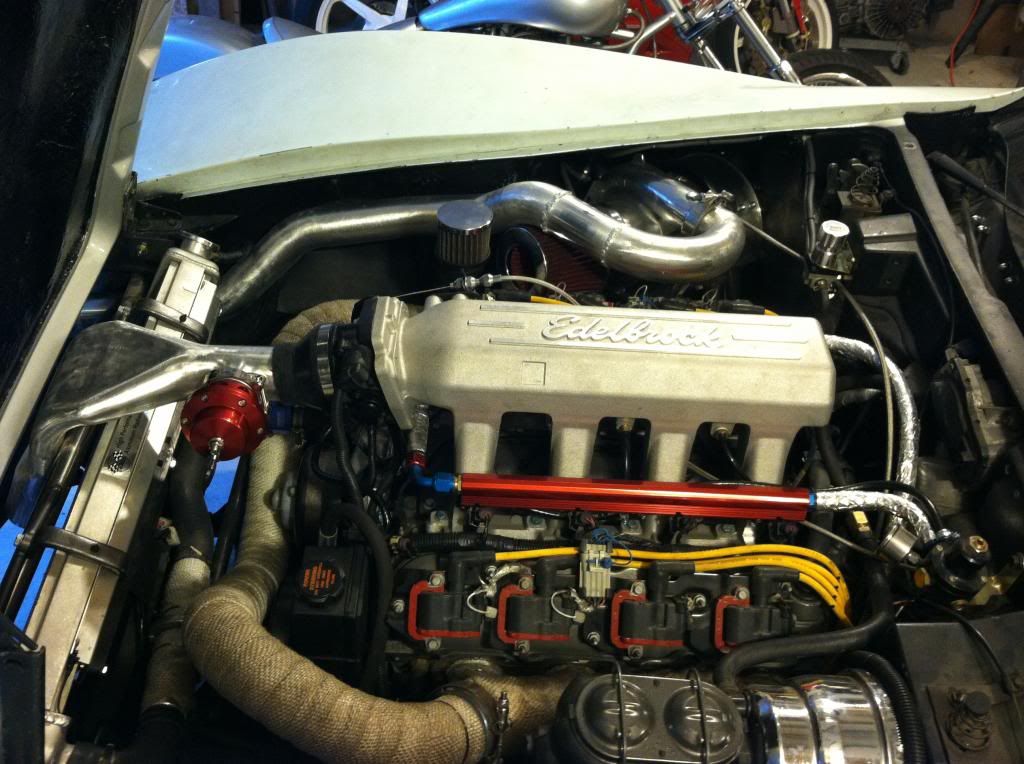
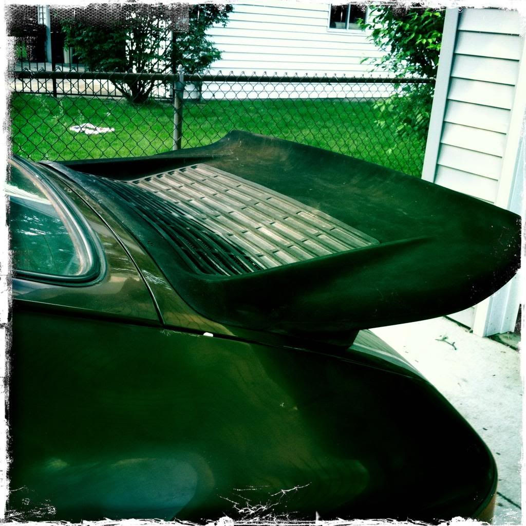
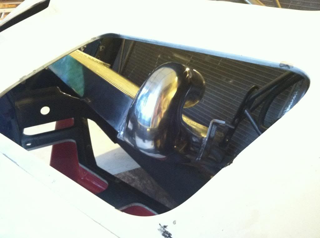
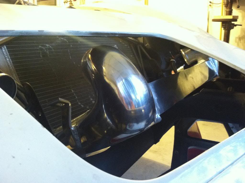
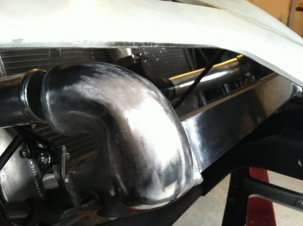
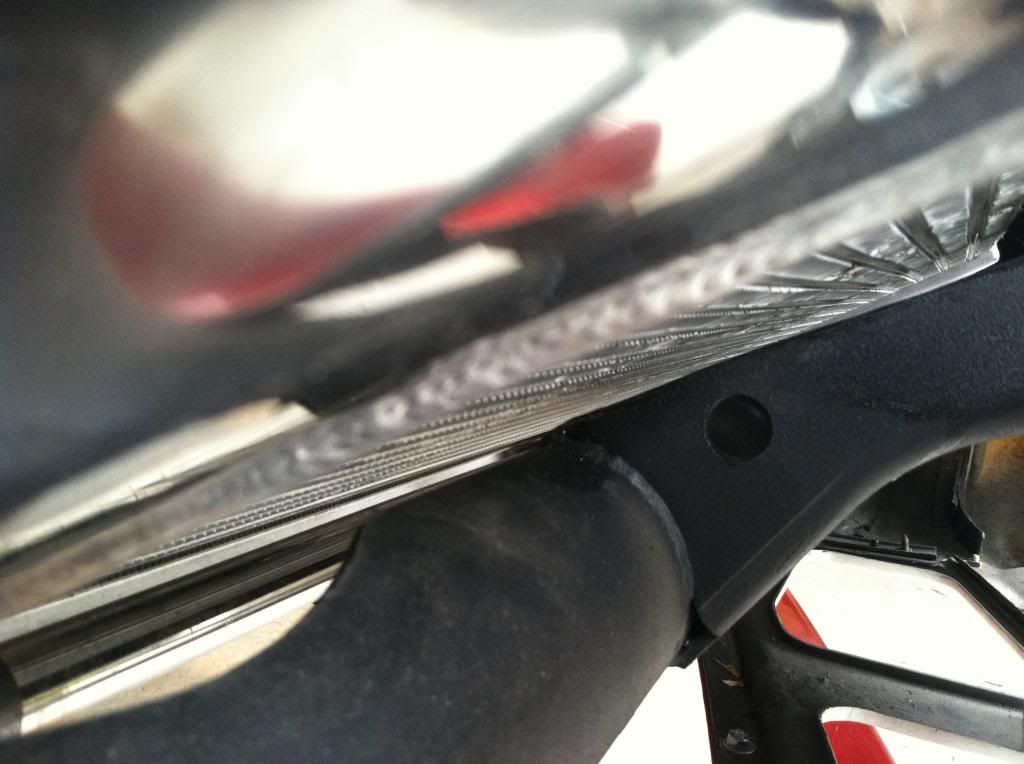
I fixed my voltage drop issue, and have ditched the water to air setup. save some weight, and simplify some things. I ended up doing what I should have done in the first place when originally started to go A2A. I made a slim wide transition section to go over the radiator and maintain hood clearance. I am now going to be running an A2A in front of the radiator the same way I had the heat exchanger for the W2A setup V-Mounted. I refabed most of the piping leading up to the intercooler.
Here is the transition I made over the rad, much like the factory corvette units but not plastic.
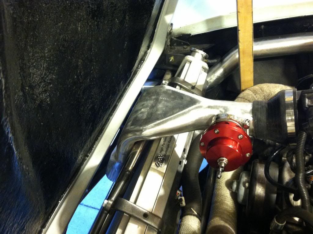
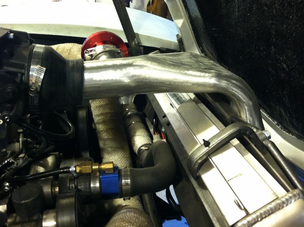
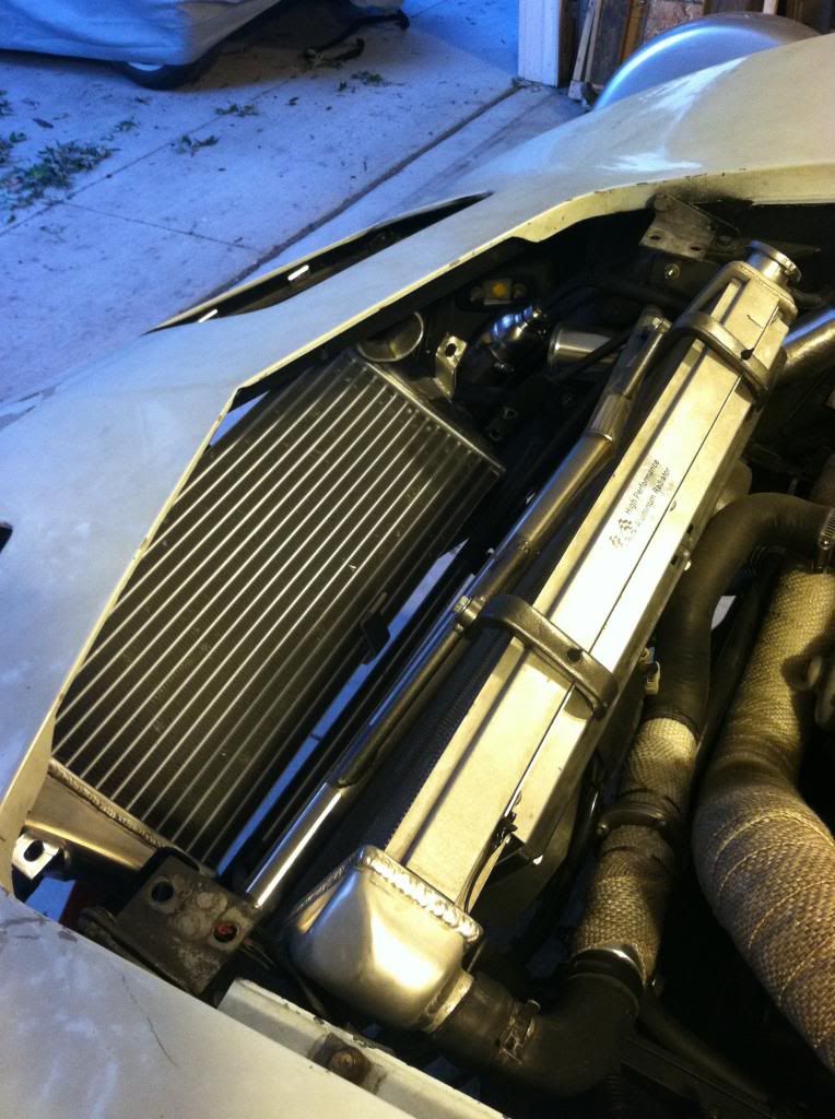
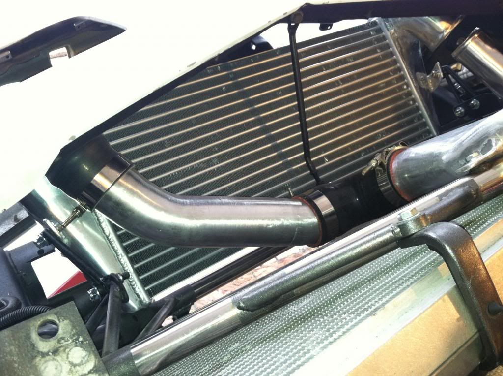
The routing of the intercooler piping now is tucked up pretty close to the fender wells, and does a little up and over the filter to go down the side of the radiator.
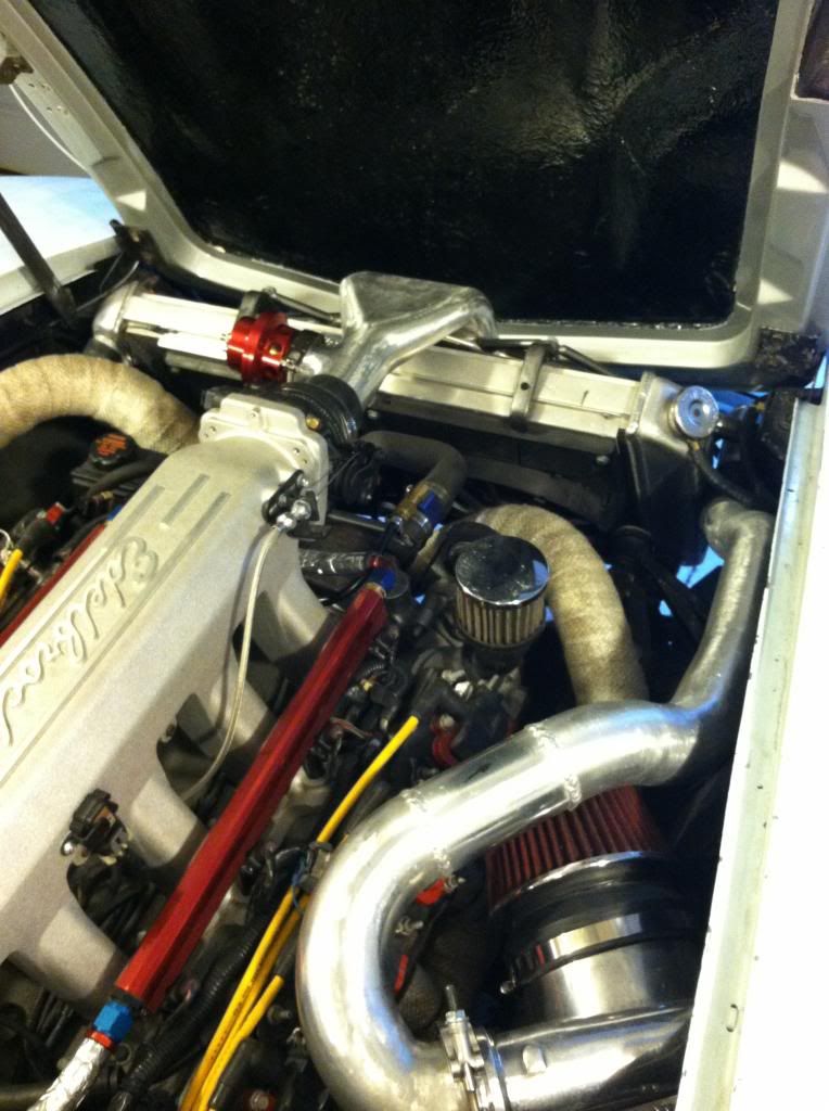
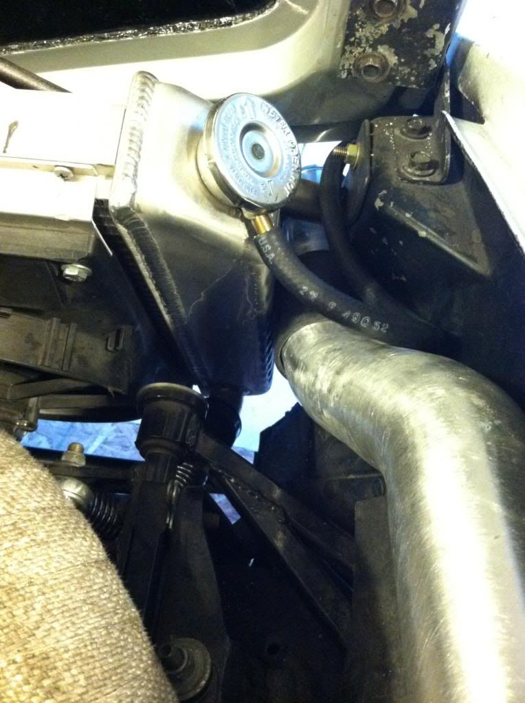
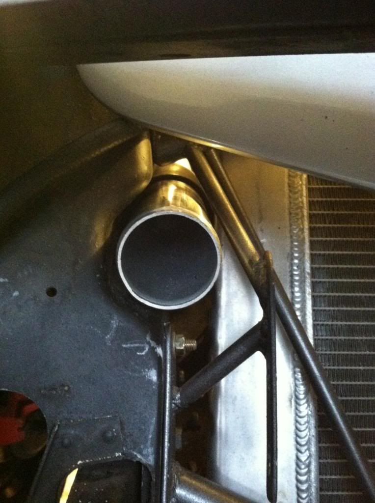
here is where the piping routs to the side of the rad and through the radiotor support I orignially fabed for this reason. Its a super snug fit, but also a perfect fit and I'm using a coupler to give a cushion between the metal.
I also got a bit more work done on the interior center console. Still need to make the panels under the top pad, and my gauge panel area for the tach, install the gauges, wrap the center console arm rest, make a shifter boot, and figure out the hydro e-brake setup and where I want it located. After I start driving it around with this new interior I will figure out if I need to wrap more surface based on heat, and reflections. I also need to start finishing some of the surfaces smoothing and polishing a bit more as I am more concrete in the forms.
The insane amount of allen bolts will be either polished, or replaced with stainless button top allen heads.
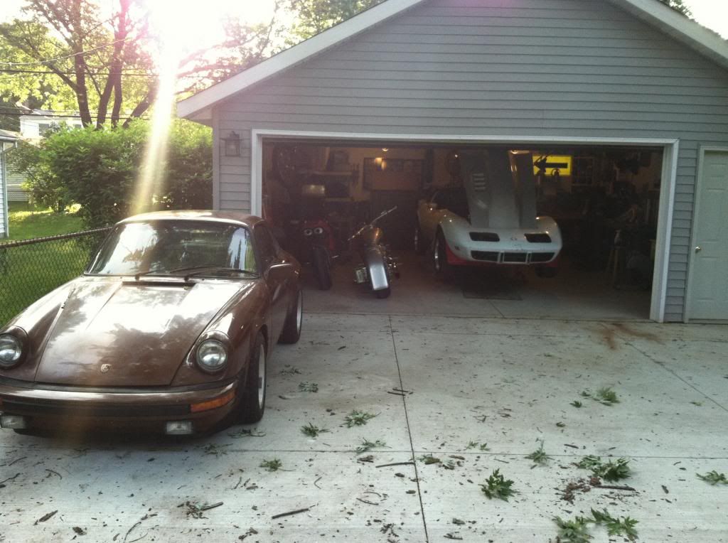
Last but not least I have added a new project to the family. It will be an LS1 swap as well. This build will be a bit more extensive, caged, custom widebody I will be sculpting and pulling molds off of, and of course a custom interior. A build thread on this will be in the near future once I get the corvette to a happy stopping point to be comfortable driving it around and not doing much more major work.

Here is the transition I made over the rad, much like the factory corvette units but not plastic.


The routing of the intercooler piping now is tucked up pretty close to the fender wells, and does a little up and over the filter to go down the side of the radiator.


here is where the piping routs to the side of the rad and through the radiotor support I orignially fabed for this reason. Its a super snug fit, but also a perfect fit and I'm using a coupler to give a cushion between the metal.


I also got a bit more work done on the interior center console. Still need to make the panels under the top pad, and my gauge panel area for the tach, install the gauges, wrap the center console arm rest, make a shifter boot, and figure out the hydro e-brake setup and where I want it located. After I start driving it around with this new interior I will figure out if I need to wrap more surface based on heat, and reflections. I also need to start finishing some of the surfaces smoothing and polishing a bit more as I am more concrete in the forms.
The insane amount of allen bolts will be either polished, or replaced with stainless button top allen heads.


Last but not least I have added a new project to the family. It will be an LS1 swap as well. This build will be a bit more extensive, caged, custom widebody I will be sculpting and pulling molds off of, and of course a custom interior. A build thread on this will be in the near future once I get the corvette to a happy stopping point to be comfortable driving it around and not doing much more major work.


Last edited by User-c3; 06-25-2013 at 07:17 AM.
06-25-2013, 07:58 AM
#90
Launching!
Thread Starter
Join Date: Jul 2011
Location: Detroit, Michigan
Posts: 209
Likes: 0
Received 0 Likes
on
0 Posts
06-25-2013, 08:51 AM
#91
Launching!
Thread Starter
Join Date: Jul 2011
Location: Detroit, Michigan
Posts: 209
Likes: 0
Received 0 Likes
on
0 Posts
started placing the intercooler last night. I have chopped a large amount of material out of the front support sections to cut weight and also give clearances. The weight I took out of the vacume cylinder that was in front was almost equal to the weight of the turbo. This intercooler location is also going to give me a few more complications when I start fabing the headlight buckets. Still not sure completely how I am going to approach that.


 07-30-2013, 10:10 AM
#92
Launching!
Thread Starter
Join Date: Jul 2011
Location: Detroit, Michigan
Posts: 209
Likes: 0
Received 0 Likes
on
0 Posts
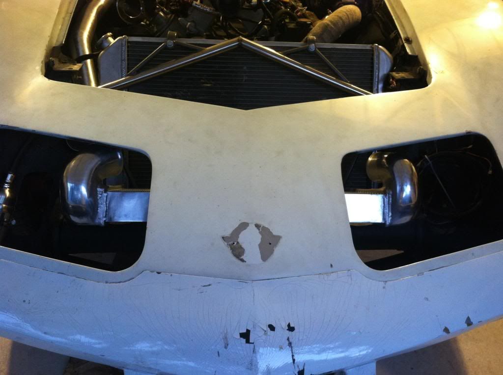
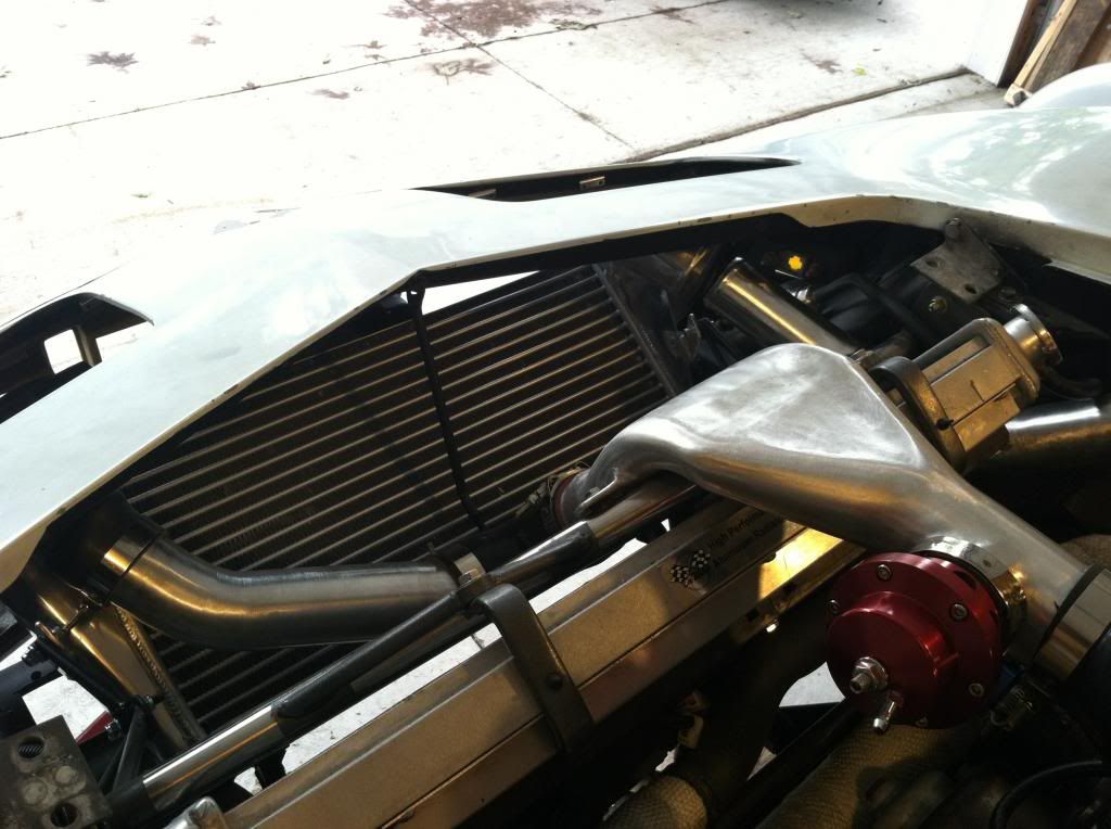
The car is back, and running. Drove it in to work today. Still having some boost issues. Boost comes on full at 3-3500 rpm and then falls off in the higher the rpms. I'm thinking its still an intercooler restriction which is frustrating. But at least its back on the road. Here is how the intercooler setup came out.
The mounts
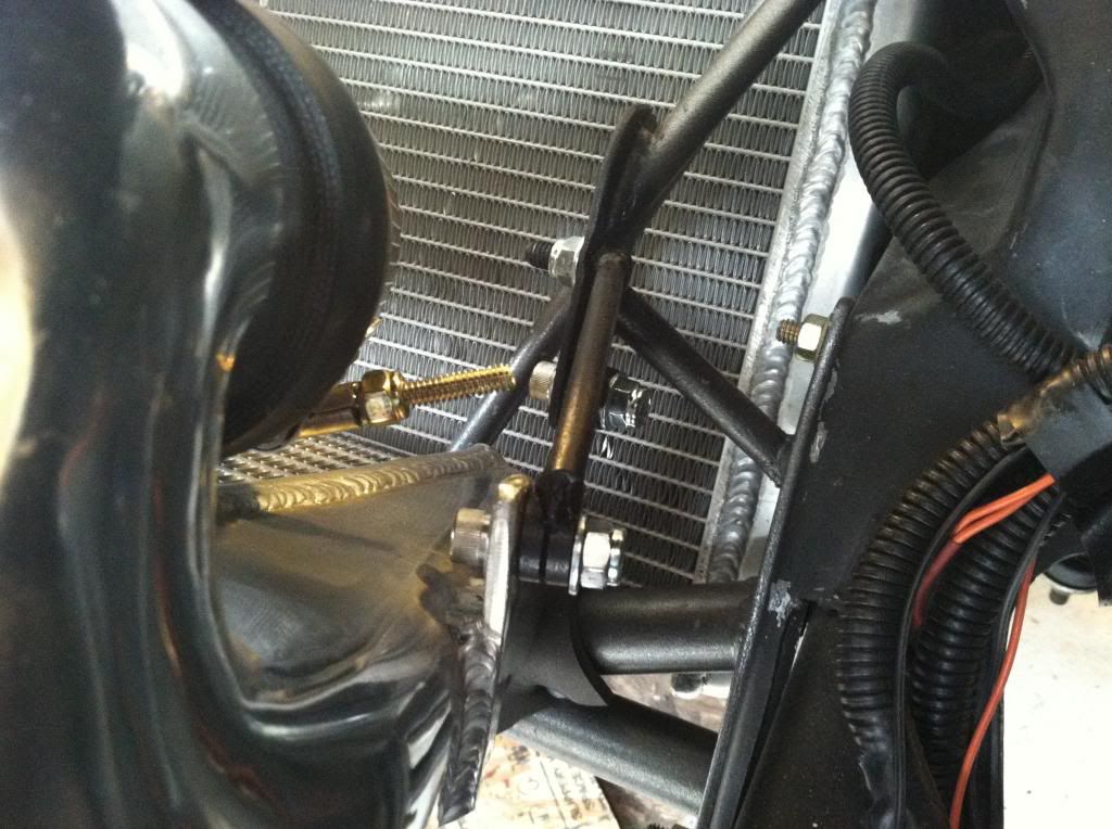
I had to cut off the intercooler intake pipe and turn it and reweld it on so it came in the right direction. The intake side is 3" and my tubing is 2.5. This also shows the mounting
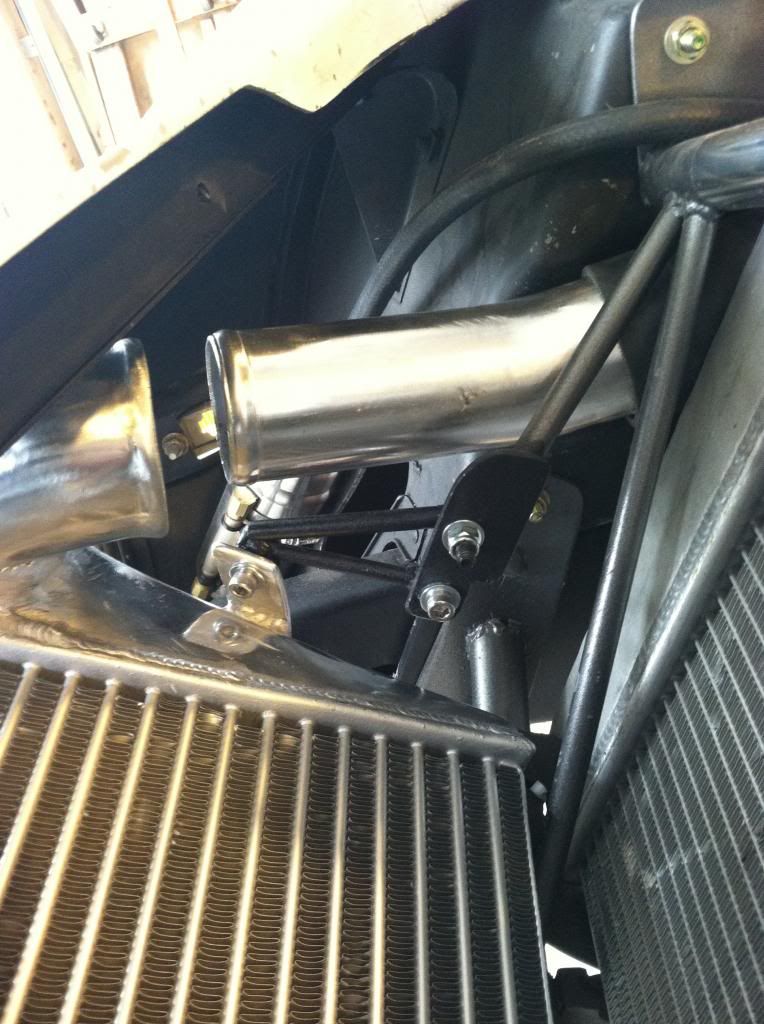
I had to do a bit of notching off the front structure to clear the intercooler. Its super tight for space trying to use the factory front structure, its going to make it even more difficult if the intercooler size is whats restricting flow.
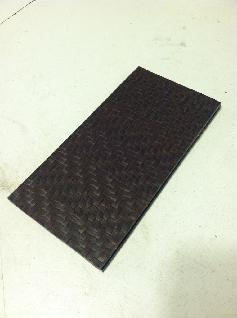
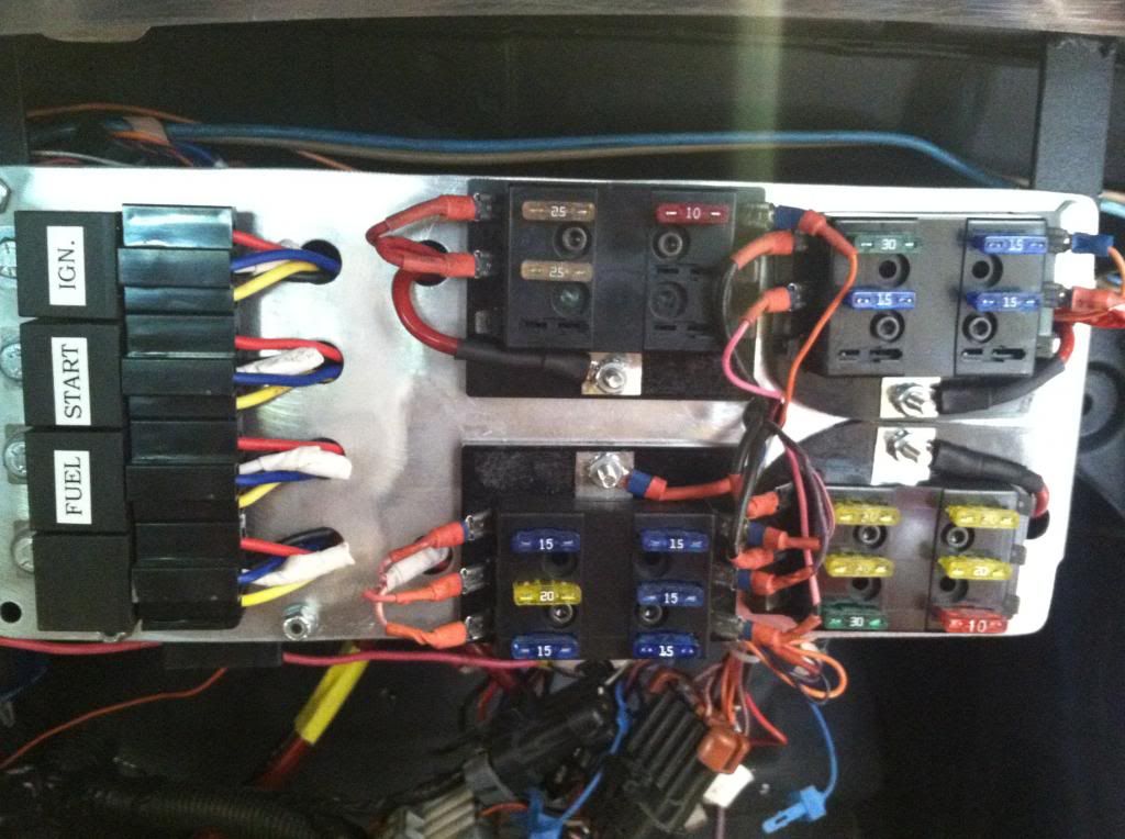
I also made a little index book to show mee what fuses are for what
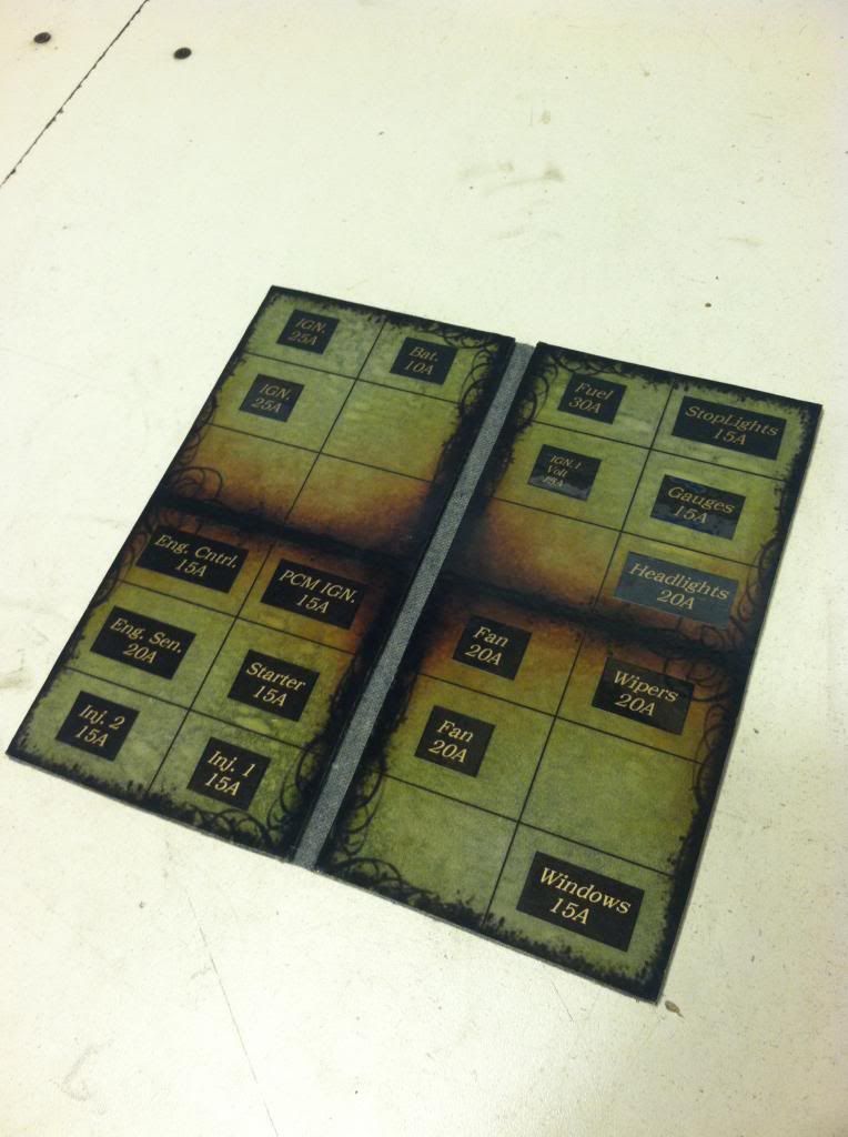
folds up like a nice clean book. I wrapped it in the same material I will be using on the console and dash and doors accented.
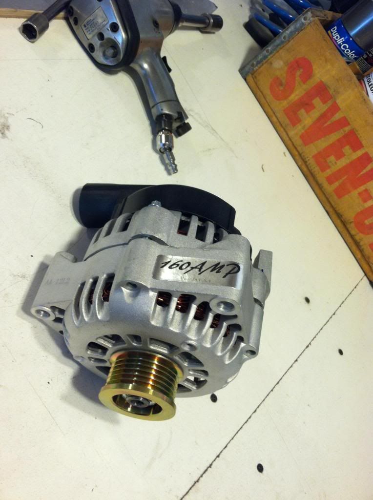
I also upgraded to a 160 amp alternator. its getting pretty hot under the hood and I think the temps are affecting the voltage output.


The mounts

I had to cut off the intercooler intake pipe and turn it and reweld it on so it came in the right direction. The intake side is 3" and my tubing is 2.5. This also shows the mounting


I had to do a bit of notching off the front structure to clear the intercooler. Its super tight for space trying to use the factory front structure, its going to make it even more difficult if the intercooler size is whats restricting flow.

I also made a little index book to show mee what fuses are for what

folds up like a nice clean book. I wrapped it in the same material I will be using on the console and dash and doors accented.


I also upgraded to a 160 amp alternator. its getting pretty hot under the hood and I think the temps are affecting the voltage output.


Last edited by User-c3; 07-30-2013 at 10:15 AM.
08-06-2013, 10:34 AM
#93
Launching!
Thread Starter
Join Date: Jul 2011
Location: Detroit, Michigan
Posts: 209
Likes: 0
Received 0 Likes
on
0 Posts
In trying to track down my lack of boost pressure I found out I had some major boost leaks. No one said this stuff was easy.
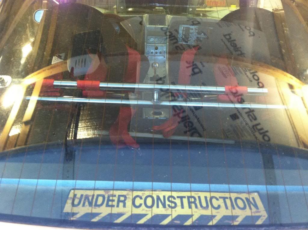
I put together a pretty simple and easy boost leak test. heres a little video I made. You can see how much air was blowing out of my throttle body. I also had to fix a couple spots on the piping where I smoothed out the welds and created some leaks.
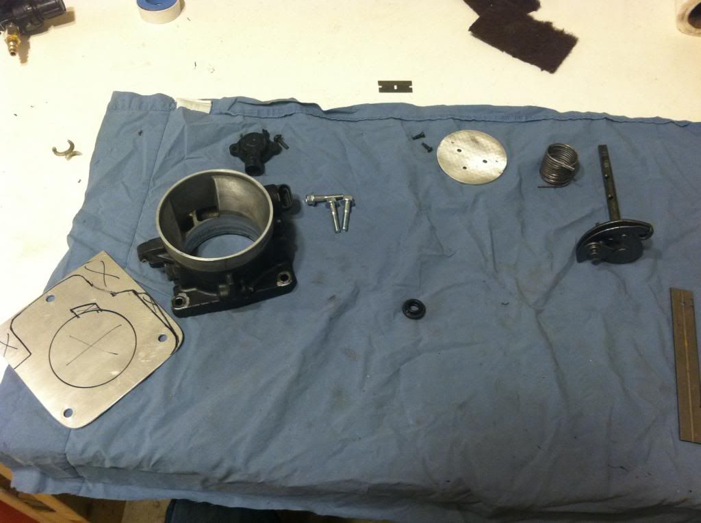
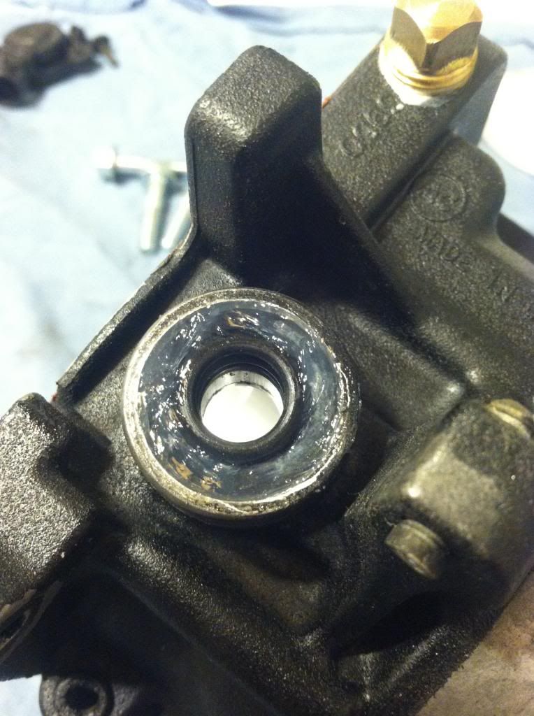
I found the seal on the shaft for throttle blade was not doing anything as far as holding in air pressure so I started trying to see if I could track one down or figure something out. Seems nobody has any knowledge about this, or seems to have had the same problem and you also cant purchase the seal. Either way I have had this thing apart and back on 2 or 3 times now
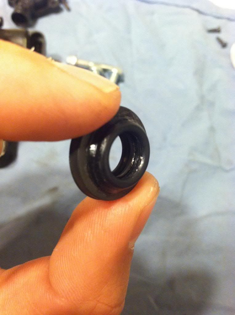
Here is the seal after I have made a couple modifications to it. I have added O-rings to both sides to creat more contact area as well as turned the seal around in the throttle body. The seal sort of flanged out to the outside and I think this allowed it to just let air escape out of it. My hope is by turning it around it puts pressure on it and creates a tighter seal. My hope!
Here you can see the now 3 layers of the seal
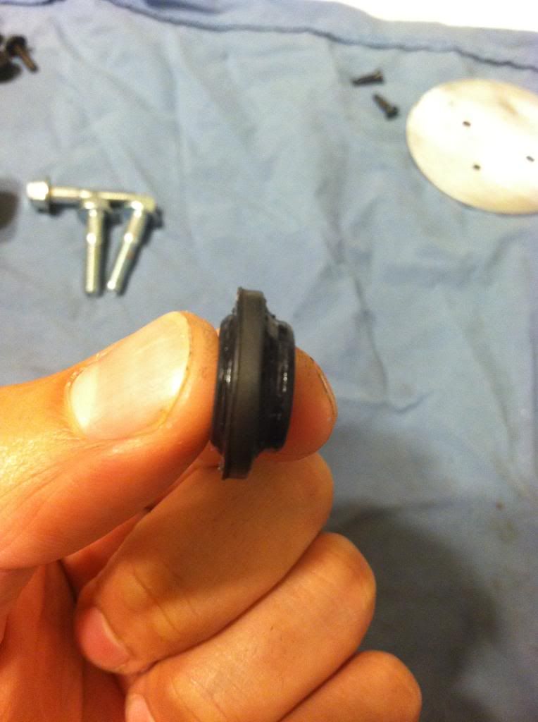
I also siliconed it into the housing to make sure it doesnt get blown out or let air escape out the sides
Its back together now and the blade opens and snaps shut just as it did before so I am almost 100% there will be no sticky situations....
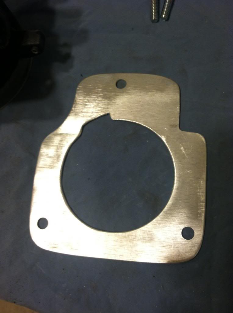
I also found out from my multiple on offs of the TB that it hardly even covered the opening on the intake manifold. The manifold has a 92mm opening and stock TB's are 76mm. So I made a plate that will make up the difference.
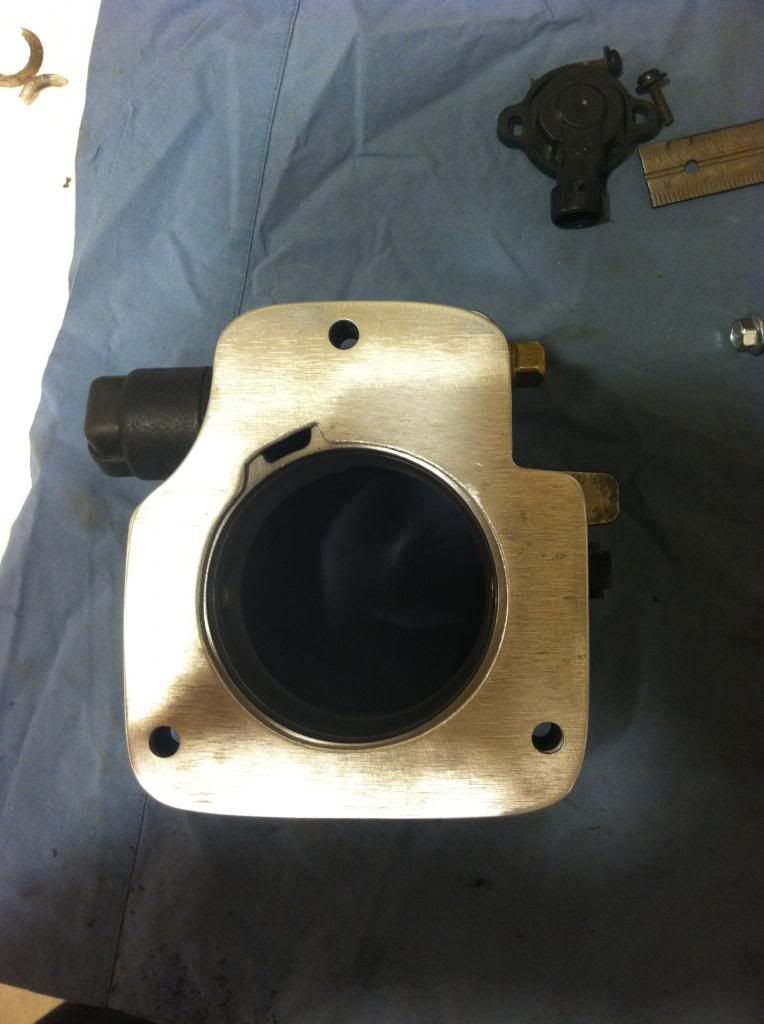
Its back on now and waiting for another pressure test tonight. I am hoping it works or at least makes it a small enough leak to be tolerated.
I put together a pretty simple and easy boost leak test. heres a little video I made. You can see how much air was blowing out of my throttle body. I also had to fix a couple spots on the piping where I smoothed out the welds and created some leaks.
I found the seal on the shaft for throttle blade was not doing anything as far as holding in air pressure so I started trying to see if I could track one down or figure something out. Seems nobody has any knowledge about this, or seems to have had the same problem and you also cant purchase the seal. Either way I have had this thing apart and back on 2 or 3 times now

Here is the seal after I have made a couple modifications to it. I have added O-rings to both sides to creat more contact area as well as turned the seal around in the throttle body. The seal sort of flanged out to the outside and I think this allowed it to just let air escape out of it. My hope is by turning it around it puts pressure on it and creates a tighter seal. My hope!
Here you can see the now 3 layers of the seal


I also siliconed it into the housing to make sure it doesnt get blown out or let air escape out the sides

Its back together now and the blade opens and snaps shut just as it did before so I am almost 100% there will be no sticky situations....
I also found out from my multiple on offs of the TB that it hardly even covered the opening on the intake manifold. The manifold has a 92mm opening and stock TB's are 76mm. So I made a plate that will make up the difference.


Its back on now and waiting for another pressure test tonight. I am hoping it works or at least makes it a small enough leak to be tolerated.
 08-07-2013, 08:23 AM
#96
Launching!
Thread Starter
Join Date: Jul 2011
Location: Detroit, Michigan
Posts: 209
Likes: 0
Received 0 Likes
on
0 Posts
08-07-2013, 09:21 AM
#98
Launching!
Thread Starter
Join Date: Jul 2011
Location: Detroit, Michigan
Posts: 209
Likes: 0
Received 0 Likes
on
0 Posts
I dont have a part number for it right now, might be able to get it off the plate tonight. I dont have much to compare it to with this being my first turbo project, but it comes on full boost at 3500rpm. So all and all pretty fantastic. Cruising on the freeway in 6th gear it builds boost and 2000rpm
 08-07-2013, 11:36 AM
#100
TECH Resident

Join Date: Nov 2009
Posts: 751
Likes: 0
Received 0 Likes
on
0 Posts

My HX55 is the less desirable 22cm exhaust housing and was turned down on a lathe and mated with a 3.5 inch outlet so I'm hoping I don't have to change housings later on..
There is a guy on here somewhere that built an 06 GTO with an HX55 that was a 19cm housing.. I have his part #s just curious if you have the same one..
3500rpm is pretty good though, how many pounds are you running?

There is a guy on here somewhere that built an 06 GTO with an HX55 that was a 19cm housing.. I have his part #s just curious if you have the same one..
3500rpm is pretty good though, how many pounds are you running?