

1967 Cougar build (over 500 pictures and videos)
 11-20-2014, 09:47 AM
#81
TECH Senior Member
Thread Starter
iTrader: (7)

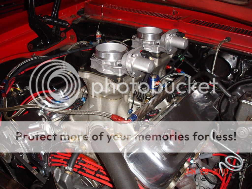
This functionality is built into the Dominator ECU and you can program the rate at which the throttle bodies open based on your driving preference. The throttle bodies have the TPS built in, so the Dominator "knows" how far the blades are open.
With the programming, you can set the throttle body rate of opening with respect to pedal position. There is table that you program with pedal % travel on one axis and the TB % opening on the other axis. Most mechanical throttle bodies have a cam that controls the rate and it is not linear. You want the pedal to be less sensitive at off-idle and part throttle, but after 50% pedal, you can ramp it in quickly. So essentially the pedal rate of opening and the throttle rate of opening will show an exponential curve. Something like this, but not exactly:

Doug F. from Holley has been running this kind of set-up since 2010, without any issues:
Andrew
Last edited by Project GatTagO; 11-20-2014 at 09:54 AM.


 11-22-2014, 09:29 PM
#83
TECH Senior Member
Thread Starter
iTrader: (7)
Had a little time to mess around with some small stuff on the engine today. I was unable to use the truck style injectors with the Holley Hi-Ram intake. I ran across a good deal on some stock LS3 injectors, which are shorter than the truck injectors. Holley make little adapter brackets that allow the use of the shorter injectors with the Hi-Ram.

The injectors slip nicely into the Holley fuel rail, but the OEM o-rings on the bottom of the injectors are too big for the Hi-Ram.

In the kit with the little brackets Holley also includes the right o-rings to work with the Hi-Ram. Stock o-ring on the left, Holley on the right.

Even with the smaller o-rings the injectors fit very tightly in the Hi-Ram. I used a little o-ring grease to make the job easier.

All assembled.

I also got my engine rotated and lined up the cam. I'll do the cam swap tomorrow.

Andrew
The injectors slip nicely into the Holley fuel rail, but the OEM o-rings on the bottom of the injectors are too big for the Hi-Ram.
In the kit with the little brackets Holley also includes the right o-rings to work with the Hi-Ram. Stock o-ring on the left, Holley on the right.
Even with the smaller o-rings the injectors fit very tightly in the Hi-Ram. I used a little o-ring grease to make the job easier.
All assembled.
I also got my engine rotated and lined up the cam. I'll do the cam swap tomorrow.
Andrew
11-23-2014, 10:01 AM
#84


The following users liked this post:
transam5.7lt1 (01-31-2020)
11-23-2014, 11:56 PM
#85
TECH Senior Member
Thread Starter
iTrader: (7)
Today I had a chance to play with the engine. I bought an ASA cam and all of the various parts to make this cam work in my engine. The first step in swapping a cam in a LS Gen IV engines is to remove all of the valve train components:

Once I lined up the cam gear with the crank gear, it was time to take off the timing chain and the chain tensioner.

In order to make the cam removal easy, I turned the engine upside down. If the engine is still in the car, there are various other procedures that you can follow. With the engine upside down, there is no chance of lifters falling down, which make swapping cams very simple. Here is the old cam on the left and the ASA cam on the right. The difference is pretty simple to see!

The stock cam was a single bolt design, which is common for Gen IV engines. With the engine on the engine stand, the best way to install the cam is to flip the engine upside down. This will keep the filters from falling down after removing the stock cam. The new cam is a 3 bolt design, but it needs to be compatible with the 58 tooth crank gear and the 4 pulse cam sensor. The best way to install the cam is to use the water pump bolts and slide her in:

Once the cam is installed, bolt in the cam retainer plate to spec:

Here is the new cam, with the 3 bolt cam gear, and the 4x signal. I also like the Gen IV timing chain tensioner.

Once the cam is installed, I use the oil pump alignment too to make sure that the oil pump gear is properly seated:

After the oil pump was installed, it was time to install the front cover. Aligning the front cover is fairly simple in the "up and down" direction, but it gets to be challenging to align the cover "left and right." I knocked out the front seal from the front cover and I used this tool to align the cover properly over the crank:

With the front cover aligned with the tool, it is still important to make sure that the cover is level with the block:

With the front cover bolted in perfectly, you need to put some RTV between the block/front cover/oil pan to make a perfect seal:

With everything lined up, the pan can be installed:

The Holley valve covers add a very nice touch to the engine:

Taken together this is turning out to be a pretty awesome looking engine package:

I was looking at the front steam vent cross over tube and the one that came with the engine didn't have the right tube exit. I found an older front cross over tube that had better routing, but I noticed that the seals to the heads were different. So it you are ever in a situation where you want to swap the front crossover tube, make sure that the gaskets are right. The tube on the right (top) has the later style tube that uses an o-ring, while the earlier tubes used a gasket with an integral o-ring:

I also drilled the water pump for the steam vent. There is a lot of drama on the forums regarding the placement of this line, but this solution has been good on my GTO since 2008, so I am sticking with itL

I tapped it for 1/16" NPT. I will find a fitting to go with the 1/16" NPT to 1/4" barb and call it a day.

Here is the engine in its present state...stay tuned for more updates...

Andrew
Once I lined up the cam gear with the crank gear, it was time to take off the timing chain and the chain tensioner.
In order to make the cam removal easy, I turned the engine upside down. If the engine is still in the car, there are various other procedures that you can follow. With the engine upside down, there is no chance of lifters falling down, which make swapping cams very simple. Here is the old cam on the left and the ASA cam on the right. The difference is pretty simple to see!
The stock cam was a single bolt design, which is common for Gen IV engines. With the engine on the engine stand, the best way to install the cam is to flip the engine upside down. This will keep the filters from falling down after removing the stock cam. The new cam is a 3 bolt design, but it needs to be compatible with the 58 tooth crank gear and the 4 pulse cam sensor. The best way to install the cam is to use the water pump bolts and slide her in:
Once the cam is installed, bolt in the cam retainer plate to spec:
Here is the new cam, with the 3 bolt cam gear, and the 4x signal. I also like the Gen IV timing chain tensioner.
Once the cam is installed, I use the oil pump alignment too to make sure that the oil pump gear is properly seated:
After the oil pump was installed, it was time to install the front cover. Aligning the front cover is fairly simple in the "up and down" direction, but it gets to be challenging to align the cover "left and right." I knocked out the front seal from the front cover and I used this tool to align the cover properly over the crank:
With the front cover aligned with the tool, it is still important to make sure that the cover is level with the block:
With the front cover bolted in perfectly, you need to put some RTV between the block/front cover/oil pan to make a perfect seal:
With everything lined up, the pan can be installed:
The Holley valve covers add a very nice touch to the engine:
Taken together this is turning out to be a pretty awesome looking engine package:
I was looking at the front steam vent cross over tube and the one that came with the engine didn't have the right tube exit. I found an older front cross over tube that had better routing, but I noticed that the seals to the heads were different. So it you are ever in a situation where you want to swap the front crossover tube, make sure that the gaskets are right. The tube on the right (top) has the later style tube that uses an o-ring, while the earlier tubes used a gasket with an integral o-ring:
I also drilled the water pump for the steam vent. There is a lot of drama on the forums regarding the placement of this line, but this solution has been good on my GTO since 2008, so I am sticking with itL
I tapped it for 1/16" NPT. I will find a fitting to go with the 1/16" NPT to 1/4" barb and call it a day.
Here is the engine in its present state...stay tuned for more updates...
Andrew
Last edited by Project GatTagO; 11-24-2014 at 07:18 AM.
11-24-2014, 07:11 PM
#86
TECH Senior Member
Thread Starter
iTrader: (7)
Went to the dealership today and got the little gaskets for the older style crossover tube:

Also picked up a front crank seal and installed it using my nifty tool from Sacks Corvette...

Rented a "universal" balancer install kit from Advanced Auto, and of course, it doesn't work. The threads inside the LS crank don't start for quite a ways so the shank was too short. I did what I probably wasn't supposed to. I lubes up the balancer and the crank and started to tap on the balancer with a dead block hammer. The balancer actually slipped on fairly easily for about an inch. After that, I just used the old bolt and gently tightened it until the balancer was fully seated. Easy as pie...

Andrew
Also picked up a front crank seal and installed it using my nifty tool from Sacks Corvette...
Rented a "universal" balancer install kit from Advanced Auto, and of course, it doesn't work. The threads inside the LS crank don't start for quite a ways so the shank was too short. I did what I probably wasn't supposed to. I lubes up the balancer and the crank and started to tap on the balancer with a dead block hammer. The balancer actually slipped on fairly easily for about an inch. After that, I just used the old bolt and gently tightened it until the balancer was fully seated. Easy as pie...
Andrew
11-24-2014, 07:16 PM
#87

Looking good and thanks for the Tips!!!
11-24-2014, 09:43 PM
#89
You are on your own there......No idea how it will work....
11-25-2014, 01:05 AM
#90
On The Tree

Join Date: Sep 2013
Location: Silverton, Oregon
Posts: 108
Likes: 0
Received 0 Likes
on
0 Posts
A lot of detail on your build thread. Nice. Engine looks cool. Are you going to use a hood scoop? I'm going to keep a flat hood on my build so I'm going to need to find a ls2 intake I believe.
11-25-2014, 03:44 AM
#91
Andrew,
So I take it you are very happy with the SacCityCorvette install hubs? They do look like the ultimate "cheap and EASY" solution. I wish I had mine BEFORE I swapped my pan and TC.
Keep up the great work !!!
So I take it you are very happy with the SacCityCorvette install hubs? They do look like the ultimate "cheap and EASY" solution. I wish I had mine BEFORE I swapped my pan and TC.
Keep up the great work !!!
11-25-2014, 09:16 AM
#92
Teching In
iTrader: (1)
Join Date: Jan 2012
Location: Port Clinton, OH
Posts: 28
Likes: 0
Received 0 Likes
on
0 Posts
 11-25-2014, 09:32 AM
#93
TECH Senior Member
Thread Starter
iTrader: (7)
Andrew
11-25-2014, 09:34 AM
#95
11-25-2014, 02:04 PM
#96
Teching In
iTrader: (1)
Join Date: Jan 2012
Location: Port Clinton, OH
Posts: 28
Likes: 0
Received 0 Likes
on
0 Posts
Keep up the good work! I subscribed and will be watching!
 11-25-2014, 10:48 PM
#97
TECH Senior Member
Thread Starter
iTrader: (7)
Got a couple of beautiful driveline parts today from The DriveShaft Shop. Goodbye 100 years old u-joint technology and welcome to the 21st century...
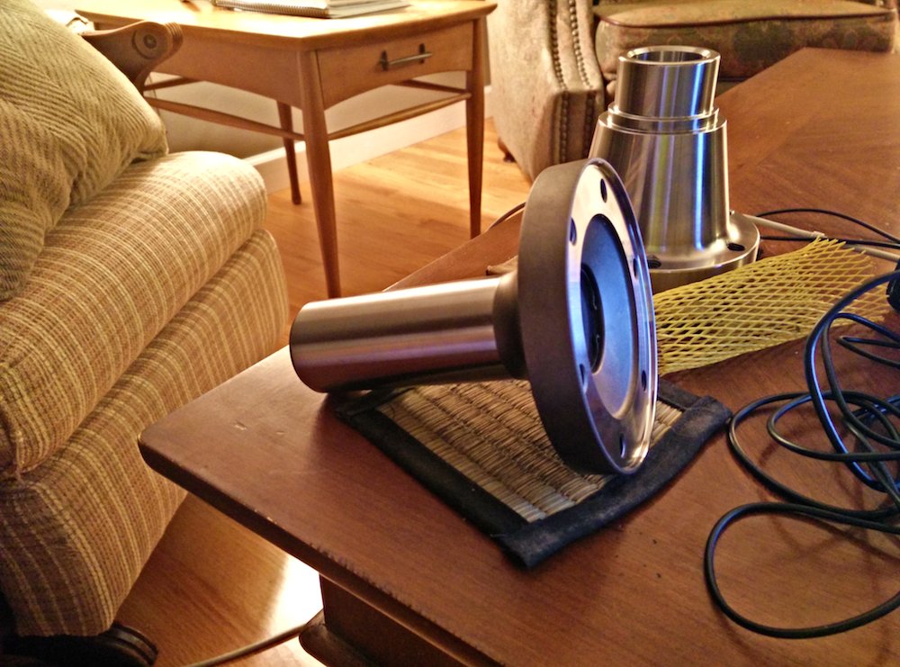
First is this 27 spline slip yoke for my T56 transmission:

It is set up to use one of their 100mm CV joints.

This beauty is a pinion flange for the 9" rear end.
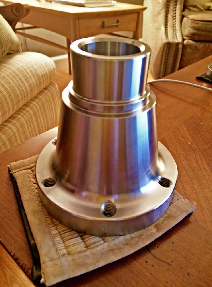
It is machined to accept one of their 108 mm CV joints.

Once I get everything installed I will measure for an aluminum driveshaft to go in the middle. Concerns about driveline angles will be a thing of the past. The front and rear operating angles don't have to be equal and opposite anymore, as long as the operating angles don't exceed 9 degrees.
This should be one smooth running cat...
Andrew
First is this 27 spline slip yoke for my T56 transmission:
It is set up to use one of their 100mm CV joints.
This beauty is a pinion flange for the 9" rear end.
It is machined to accept one of their 108 mm CV joints.
Once I get everything installed I will measure for an aluminum driveshaft to go in the middle. Concerns about driveline angles will be a thing of the past. The front and rear operating angles don't have to be equal and opposite anymore, as long as the operating angles don't exceed 9 degrees.
This should be one smooth running cat...
Andrew
The following users liked this post:
n2xlr8n66 (06-08-2022)