PCV System Diagram Based Largely on MM's
 04-12-2010, 03:32 PM
#1


It should be legible if you click on the image to make it full screen.
This is what I've pieced together from various threads and especially from MightyMouse's system. Hopefully with all the info on one sheet it will be easy to understand.
What does everyone think??
Thanks!
Adam
 04-12-2010, 05:18 PM
#2
Launching!
You could save a bunch of of hose by routing the majority of those into one or two lines leading to the catch can. It would clean the bay up as well. As far as the layout goes, it's great. However I would relocate the check valve to the hose between the manifold and booster so that it would allow the booster to see vacuum during normal driving and keep boost out. Ditch the check valve up front. If your vacuum source is in front of the turbo it won't see anything but vacuum so the check valve's literally a waste of money.
04-12-2010, 05:36 PM
#3
I thought about routing the lines into one like you mentioned, and I may end up doing that. I won't know until I try it, it may need the extra capacity of more than one line going to the can.
The booster will retain it's stock check valve and should function like like stock. I'm only adding in the second valve to block boost from going to the catch can.
I wanted the check valve in between the turbo and the catch can because under idle and low load, I was afraid the manifold vacuum would be much greater than the turbo inlet vacuum, possibly drawing air IN from the turbo inlet.
04-12-2010, 05:46 PM
#4
What do ya'll think of this for the check valves:
PVC Spring-Loaded Ball Check Valves
Maximum Pressure: 125 psi @ 140� F
Cracking Pressure: 1 psi
Temperature Range: 33� to 140� F
With a wide variety of end connections available, you're sure to find a valve that will fit in your piping system. All are made of corrosion-resistant PVC with a Type 302 stainless steel spring, Type 316 stainless steel ball, and a Buna-N seat. Color is gray. Note: Cv factor not rated. Connections: NPT, barb, or push-to-connect (see table).
They make one that has barbed ends for hoses in different sizes for $12 each. Didn't seem bad to me.
Trending Topics
04-20-2010, 01:58 PM
#10
TECH Regular
iTrader: (20)
Join Date: Mar 2007
Location: NW Burbs of Chicago
Posts: 452
Likes: 0
Received 0 Likes
on
0 Posts
Ah, I see it now. I thought that was the booster itself not a valve. Guess I should read better next time!
Here's a diagram that I'm working on today... basically the same idea. I included the vac, PCV and boost controller stuff too, just for my own sanity.
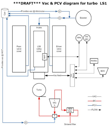
Thoughts?
Here's a diagram that I'm working on today... basically the same idea. I included the vac, PCV and boost controller stuff too, just for my own sanity.
Thoughts?