When you click on links to various merchants on this site and make a purchase, this can result in this site earning a commission. Affiliate programs and affiliations include, but are not limited to, the eBay Partner Network.
I'd think if this was an effective way to increase efficiency, you would see it in modern day OEM engines. Efficiency aside, would there be any performance benefits to a turbulent design?
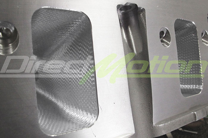
It all sounds good on paper, but I'm skeptical. Some companies are now adding CNC turbulent designs etched into the CC, Ports, Pistons, etc...
Some texture on the intake runners provide a boundary layer to aid in better flow in the center of the port. But to me anyhow the combustion chamber and exhaust port should be smoooooth.
Turbulance helps atomization and flame speed. I think this is a terrible idea though, turbulance comes from runner design and that's about it. You also want to minimize crevice volumes, not make more of them. I bet a motor with this done takes 5 less degress of spark before it pings
I had a professor who was doing a lot of research with BorgWarner and Ford in developing their EcoBoost motors. I can't remember the specifics, it was a couple years ago, but we spent a decent amount of time studying this and when turbulent flows were introduced into the combustion process, there were some significant benefits. Obviously there are some cons, but the pros were definitely there. He was all about it. We didnt get into designs like this though
Turbulance helps atomization and flame speed. I think this is a terrible idea though, turbulance comes from runner design and that's about it. You also want to minimize crevice volumes, not make more of them. I bet a motor with this done takes 5 less degress of spark before it pings
Many things affect it, not just runner length, Combustion chamber shape plays a huge part too as does injector spray, location, port shapes, valve shapes etc etc
And if the motor makes the same/more power/torque with less advance, that is always a good thing
We only run advance because combustion is a relatively slow process. If we can speed this process up which in turn means a more controlled burn, that is always good.
As to whether this sort of thing will make more power or not...they'd need to prove it with testing. Most of the OEM testing with that sort of stuff would largely be aimed at emissions rather than power.
Turbulance helps atomization and flame speed. I think this is a terrible idea though, turbulance comes from runner design and that's about it. You also want to minimize crevice volumes, not make more of them. I bet a motor with this done takes 5 less degress of spark before it pings
The tests provided in the links say otherwise. They even test some LS heads for us.
"Then, I was introduced to using a spray-type dye during airflow bench testing of cylinder heads. By studying areas where the dye was really concentrated, it appeared these locations indicated fuel wash or separation from the airflow. What really got my attention was when we started changing the surface texture of these areas and began to see power increases with little or no changes in total air or fuel flow. Exhaust gas temperatures also began to drop, suggesting the burn was taking place faster and that more of the fuel already in the combustion chamber was now being burned. We also discovered less spark timing was required for best power," Wells said.
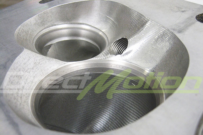
Then goes on to mention the addition of something like this can help with the problem. (though on the LS head it looks like you'd want the dimples on around the exh valve)
"Overall, there are several things (construction techniques) we've found helpful using the dye method," Wells continued. "One is that it points to where flow surface texture changes will help. We like to use dimples in these areas because they tend to put separated fuel back into the air stream. What this does is allow otherwise wasted fuel to be burned. This is power, any way you look at it. We also discovered that how air is delivered to the combustion chamber, when measuring flow patterns with a head alone, usually changes when you bolt on the intake manifold. So just studying these patterns with the effects of the manifold can be misleading. We've worked on optimizing flow patterns in the combustion chamber and discovered all this changes when the manifold is installed.
"What's really interesting is that we've used this method to identify areas of fuel separation, created dimple patterns, and found power gains without any significant changes in the amount of air flowed. Plus, we've also discovered that what we'd previously thought were helpful modifications in an intake manifold that increased air flow actually caused separation problems downstream. The bottom line of this was we didn't see power gains that the increased airflow indicated we should, which was the result of mixture quality problems we'd created by just going for more air. The old story about 'more air isn't always more power' is true in a lot of cases where these gains upset combustion efficiency.
Some texture on the intake runners provide a boundary layer to aid in better flow in the center of the port. But to me anyhow the combustion chamber and exhaust port should be smoooooth.
I had always heard of all the big turbo guys "softening" the CC as well. That's why I found this so interesting. I've yet to see any back-to-back comparisons of turbo engines doing this. So I don't see how one could say with certainty it is a good or bad idea. If what they are saying is true, then wouldn't softening the chamber have the opposite effect? Requiring more fuel and timing to make the same power, while slowing combustion?
How would a more complete distribution of fuel in the CC ever be a bad thing? Why would this be more prone to detonation with FI? Wouldn't turbulent A/F mixtures require less timing due to a more efficient/faster burn rate? Something like this could easily be conceived as a "bad thing" in a back-to-back test if timing was not reduced while monitoring fuel flow and power output. If it was proven beneficial NA, why would it not make power with forced induction?
Again this is all just random thoughts. I am talking about helping along a factory casting head at factory RPM ranges for a few additional HP. Not an "all out" performance race head.
Last edited by Forcefed86; 12-04-2014 at 01:07 PM.
Exhaust ports should be smooth as there is only dry flow, the intake port has to deal with wet flow which can cause fuel to stick to the port walls. Energizing the boundary layers coaxes these fuel deposits to continue to flow through the port or evaporate.
This style of porting does not impact flow. That is not its purpose.
This is what the intake charge in the intake port looks like in terms of velocity. Air speed at the port wall is zero. Due to the wetting action of the fluids in the intake port. The rest of the charge has to shear past this. Exciting the boundary layer helps accomplish this better and create a more uniform velocity profile.
Port shape also plays into VP, and a turbulent port due to excessive port velocity and improper shape should not be confused with fuel separation. Turbulence in the intake port is not a good thing on a high performance engine.
The more uniform the VP the better. Mixture motion in the cylinder is improved, throttle response comes up, torque production comes up and the engine all around just runs better and responds to changes more noticeably.
Airplane wings utilize boundary layers and laminar/turbulent flow to create lift and set drag.
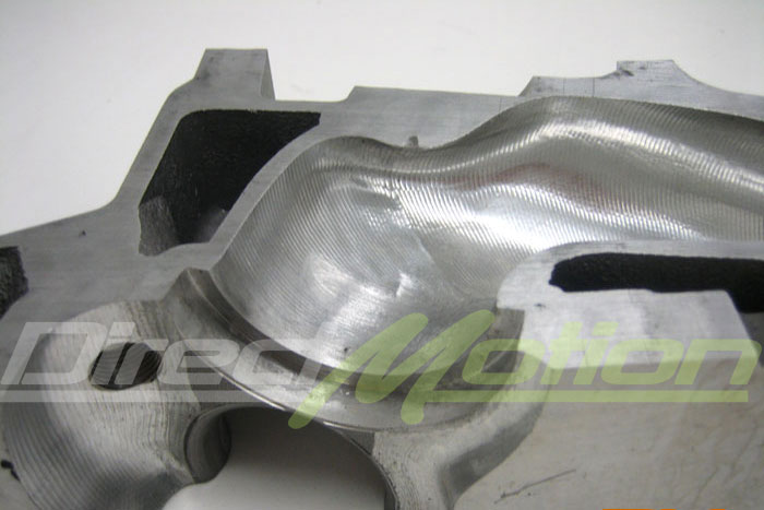
Here is a good article that Larry Meaux was interviewed on that shows a burr finish he uses to help with mixture motion and fuel evaporation.
Exhaust ports should be smooth as there is only dry flow, the intake port has to deal with wet flow which can cause fuel to stick to the port walls. Energizing the boundary layers coaxes these fuel deposits to continue to flow through the port or evaporate.
This style of porting does not impact flow. That is not its purpose.
This is what the intake charge in the intake port looks like in terms of velocity. Air speed at the port wall is zero. Due to the wetting action of the fluids in the intake port. The rest of the charge has to shear past this. Exciting the boundary layer helps accomplish this better and create a more uniform velocity profile.
Port shape also plays into VP, and a turbulent port due to excessive port velocity and improper shape should not be confused with fuel separation. Turbulence in the intake port is not a good thing on a high performance engine.
The more uniform the VP the better. Mixture motion in the cylinder is improved, throttle response comes up, torque production comes up and the engine all around just runs better and responds to changes more noticeably.
Airplane wings utilize boundary layers and laminar/turbulent flow to create lift and set drag.
Here is a good article that Larry Meaux was interviewed on that shows a burr finish he uses to help with mixture motion and fuel evaporation.
Appreciate the reply. I’m not trying to argue, I am skeptical as well.
As Larry Meaux has demonstrated power gain is typical with a “rough port”. The rougher the port the higher the gain in his testing. If it were this easy to improve power at the same fuel flow, why wouldn’t all the OEM manufactures do it? They could add similar into the casting without much difficulty.
As we’ve all seen with the golf ball, It’s proven that a dimple texture helps establish air boundary layers. If this is the case, why wouldn’t it apply to a Dry port surface? I'd think it would reduce flow separation and also reduce turbulence, even with no fluid present.
As you say, I’ve seen indycar and nascar heads and they are perfectly smooth. But that’s comparing apples to oranges.
If I were to dyno a 100% factory stock 6.0 with and without these “dimples” all the tests indicate I would see improved performance at the same fuel flow with less timing. These tests have been duplicated many times with repeatable results. So again, how would these gains not transfer over to a boosted situation? How would turbulent flow decrease the knock threshold? Technically if the charge air velocity is increased with boost, wouldn’t the dimples effects be magnified? You would have a faster moving air/fuel mix, so when it hit a dimple it would have more energy to spread the fuel. Sort of like a spoon under a faucet.
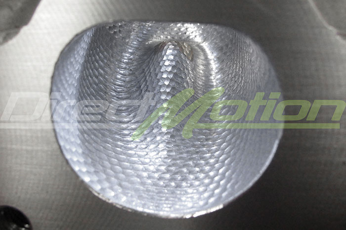
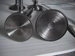
Heres another great article about the funky piston picture I posted above.
Ross provided the forged pistons that Johnston and Milano modified in-house. "We did dimple the tops of the pistons and the combustion chambers to help atomize the fuel," he says. When asked about any empirical evidence that the dimpling did anything to actually help, Johnston referred back to a 409 Pontiac he built for a previous EMC competition. They tested that engine with stock-type chambers first. "It looked fat in areas and the combustion chamber had wet spots where it would puddle in there. I thought, 'You know what, I'm gonna try this.' Because I've seen some articles done on this but I've never seen any testing and nobody knows where to put these things, so I just kind of randomly made it look like a golf ball in the combustion chamber. We didn't do anything to the pistons on that motor." Between just the dimpling of the chamber and also changing the spark plug depth where the electrode would protrude slightly into the chamber, that engine picked up almost 40 hp and Johnston was sold. With the dimpling done to this 455, the pistons and chambers looked like fuel had never touched them. They were also able to run significantly less timing for best power.
Last edited by Forcefed86; 12-04-2014 at 08:54 PM.
Appreciate the reply. I’m not trying to argue, I am skeptical as well.
As Larry Meaux has demonstrated power gain is typical with a “rough port”. The rougher the port the higher the again in his testing. If it were this easy to improve power at the same fuel flow, why wouldn’t all the OEM manufactures do it? They could add similar into the casting without much difficulty.
As we’ve all seen with the golf ball, It’s proven that a dimple texture helps establish air boundary layers. If this is the case, why wouldn’t it apply to a port Dry port surface? I'd think it would reduces flow separation and also reduce turbulence with no fluid present?
As you say, I’ve seen indycar and nascar heads and they are perfectly smooth. But that’s comparing apples to oranges.
If I were to dyno a 100% factory stock 6.0 with and without these “dimples” all the tests indicate I would see improved performance at the same fuel flow with less timing. These tests have been duplicated many times with repeatable results. So again, how would these gains not transfer over to a boosted situation? How would turbulent flow decrease the knock threshold? Technically if the charge air velocity is increased with boost, wouldn’t the dimples effects be magnified? You would have a faster moving air/fuel mix, so when it hit a dimple it would have more energy to spread the fuel. Sort of like a spoon under a faucet.
Heres another great article about the funky piston picture I posted above.
Ever seen the wing in the port on the LSA heads? It's purpose is to induce swirl, increase tumble and therefore increase combustion efficiency. The LS7 port also utilizes this, but to a lesser extent.
Look at the new C7 LT1 cylinder heads. They did the ports that way to increase swirl, improve tumble and increase efficiency.
In a performance head it's not needed. A properly designed port does not need this rough finish or dimple porting in most head porters views because they're starting with a fresh slate and can shape the port how they want to achieve laminar flow throughout the lift curve and across the engine's operating range.
In a production head, or a head whose architecture doesn't allow for the port shape they are after to give the desired performance, things like dimpling and rough carbide burr finishes can help a lot.
I now see that Larry uses the rough finish even in his exhaust ports and I tend to have to agree with what you said regarding it helping the exhaust port flow as well. At least in terms of laminar flow.
Exhaust port flow on a bench really means very little though. The exhaust port operates at such a high depression in the real world that you can't simulate it on a bench. The same can be said about the intake port.
A good quiet smooth flowing exhaust port is what most porters aim for as they do with the intake port. Laminar flow at it's finest.
Last edited by Sales@Tick; 12-04-2014 at 02:58 PM.
I will also say that Larry has forgotten more than myself or most will ever know. He says that he uses the rough finish on every cylinder head and intake he ports now.
Every head porter has a different view on things, but most will agree on principle and physics. How to get to the end results is where most do things differently.
Some porters don't utilize the rough finish in their ports, and only in the intake manifold. Or they may use a smoother finish in the intake ports than they do in the intake manifold. Some only use a rough finish on the plenum floor in the intake.
I think it all comes down to what you're comfortable with and what you've tested.
I am not an expert by any means but I do buy in. I have seen this effect when racing sailboats for quite some time. A thin layer of water loosely adhered to the hull tends to be faster than a slick hull. However, the effect can be positive or negative depending upon the speed of the boat through the water and how rough the surface of the hull is. The speed of water over a boat hull is obviously very different than the speed of air through a head so I have often wondered where the sweet spot would be within an engine head. I do run the LSA heads and did the P&P myself leaving the swirl wing in the intake. I did remove some of the wing structure as I believe the size was likely chosen to provide efficiency at lower rpms and therefore airflow. Should I have just left it alone? Who knows but I know that I am seeing more flow (less boost) from my blower than others using the same size pulley. Is this conclusive evidence? No but the hp and torque numbers seem to indicate something is working.
So if grooving the quench pads lowers EGT, wouldn't that negatively effect turbo spool? I thought exhaust velocity and heat retention both improve turbo spool since the hotter the exhaust is the faster is can move?
 11-25-2014, 09:08 AM