
PCV Catch Can Setup/Writeup... PICS!!
 09-05-2010, 11:24 AM
#1
TECH Resident
Thread Starter
iTrader: (10)

Join Date: Oct 2008
Location: DetroitRacing.com
Posts: 823
Likes: 0
Received 0 Likes
on
0 Posts
I know that this question is asked a lot on this board so here is a write-up in progress.
This is meant to try to pull oil out of the intake mainfold and it costs very little to do.
Here is the link to the air/water seperator you use as the catch can --->
http://www.homedepot.com/webapp/wcs/...ctId=100027474
You will also need two (2) brass 1/4" NPT male thread to 3/8" hose barb fittings
You will need a decent length of 3/8" heater hose (cheap) rubber tubing.
Here are pics of the Husky oil/water seperator:

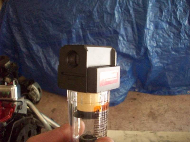
The oil/water seperator gets connected between the PCV vavle on the drivers side of the intake (shown below)
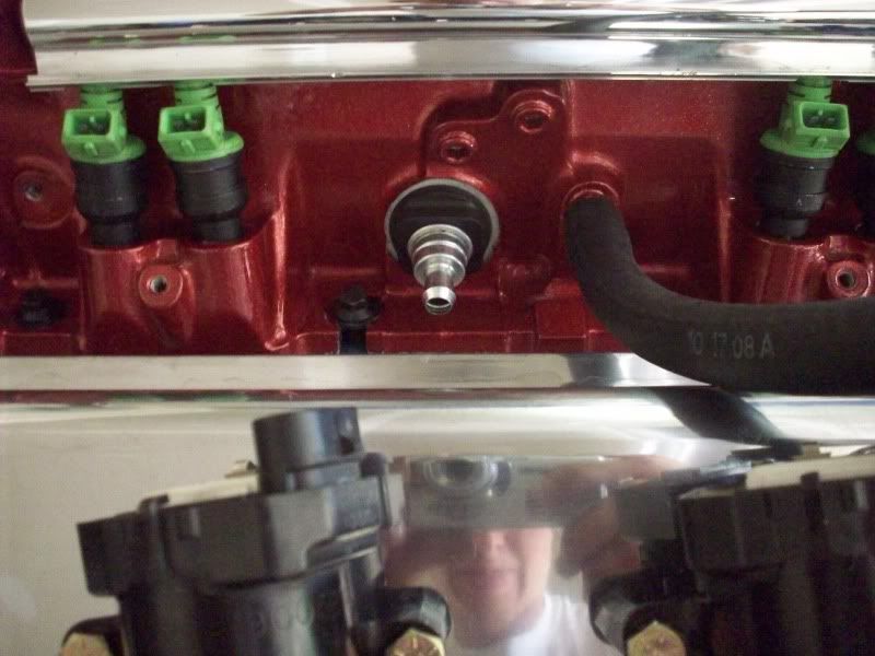
and the other end goes to the port below the throttle body (shown below)

Use as much hose as you like to mount the oil/water seperator where you want it. Mine is going below the drivers side cylinder head.
This is meant to try to pull oil out of the intake mainfold and it costs very little to do.
Here is the link to the air/water seperator you use as the catch can --->
http://www.homedepot.com/webapp/wcs/...ctId=100027474
You will also need two (2) brass 1/4" NPT male thread to 3/8" hose barb fittings
You will need a decent length of 3/8" heater hose (cheap) rubber tubing.
Here are pics of the Husky oil/water seperator:
The oil/water seperator gets connected between the PCV vavle on the drivers side of the intake (shown below)
and the other end goes to the port below the throttle body (shown below)
Use as much hose as you like to mount the oil/water seperator where you want it. Mine is going below the drivers side cylinder head.
 09-05-2010, 02:38 PM
#2
I appreciate the pics, I've been planning on rigging one of those up soon. For some reason none of my local Home Depots or Lowes carry 3/8" inside diameter fuel line or heater hose so that's my current hold up. I fabbed one up on my Mom's TBSS with a similar air compressor filter and that sucker really does work, can't beat it for the $$$. Not sure if you are aware but you will need to close up the bottom of the filter with something because oil will slowly drip out, I glued the one made for my Mom and it works perfect.
09-05-2010, 04:53 PM
#3
TECH Resident
Thread Starter
iTrader: (10)
Join Date: Oct 2008
Location: DetroitRacing.com
Posts: 823
Likes: 0
Received 0 Likes
on
0 Posts
^^ Thanks. I was looking at that. I have yet to sinstall this fully, but figured I would make a thread with pics to help anyone else that may be trying to do the same thing im doing. I do have one question though:
The oil/water seperator has an INLET and OUTLET side. Which side needs to be pointed toward the PCV valve? I just have no idea which way the air actually flows through the system
The oil/water seperator has an INLET and OUTLET side. Which side needs to be pointed toward the PCV valve? I just have no idea which way the air actually flows through the system
09-05-2010, 06:38 PM
#4
TECH Resident
iTrader: (8)

Join Date: Nov 2008
Location: el paso, tx
Posts: 778
Likes: 0
Received 0 Likes
on
0 Posts

Just did mine today don't know what happen but after install and 10 min of driving my low rpm back fire went away and knock senser reads right now and smooth as Hell up top....so call me crazy but I think the oil in the intake had something to do with it..
09-05-2010, 09:58 PM
#6

I need a pix that already on the car lol. btw I did this few year ago on mustang, and alot peoples those me that, synthetic oil will eat that yellow stuff inside the huskey. just take it off anyway.
09-05-2010, 10:09 PM
#7
^^ Thanks. I was looking at that. I have yet to sinstall this fully, but figured I would make a thread with pics to help anyone else that may be trying to do the same thing im doing. I do have one question though:
The oil/water seperator has an INLET and OUTLET side. Which side needs to be pointed toward the PCV valve? I just have no idea which way the air actually flows through the system
The oil/water seperator has an INLET and OUTLET side. Which side needs to be pointed toward the PCV valve? I just have no idea which way the air actually flows through the system
BTW, I took apart our old dishwasher today so I could scrap some of the copper and I found some 3/8" heater hose in there so I can finally rig it up.
 I can't believe they don't sell 3/8" hose around here.
 Trending Topics
09-06-2010, 10:20 AM
#9
TECH Resident
Thread Starter
iTrader: (10)
Join Date: Oct 2008
Location: DetroitRacing.com
Posts: 823
Likes: 0
Received 0 Likes
on
0 Posts
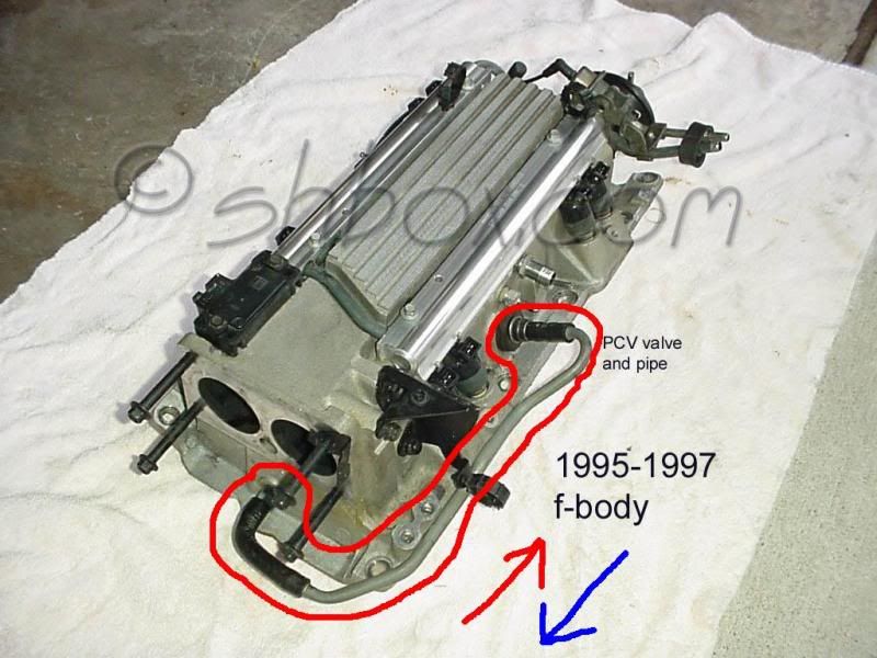
Here is a picture to describe what I need to know.
The pipe circled in red is how the stock PCV is setup on a stock car and is what the air flows throw. The Husky filter needs to get connected inline with that pipe somehow.
Does the air flow in the path of the red arrow or the blue arrow?
The pipe circled in red is how the stock PCV is setup on a stock car and is what the air flows throw. The Husky filter needs to get connected inline with that pipe somehow.
Does the air flow in the path of the red arrow or the blue arrow?
 09-06-2010, 10:28 AM
#11
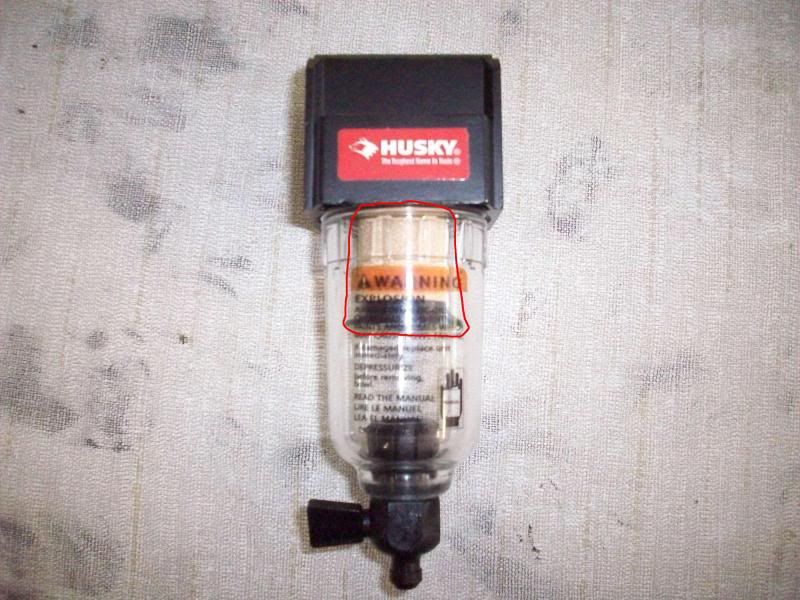
yes the sysnthetic eat away, that y i ask question year ago, i think if u look closer it should have a little sticker say " not combatible with sysnthetic " or something like that. i just take that part off.
here what it look like on my mustang

btw the version you bought , have that turn ****, it will or made leak out at the bottem, I end up have to exchange for different version, and when it time to drain the oil , i just uncrew the whole tube part and drain it out. and wipe it off with paper tower,
here what it look like on my mustang

btw the version you bought , have that turn ****, it will or made leak out at the bottem, I end up have to exchange for different version, and when it time to drain the oil , i just uncrew the whole tube part and drain it out. and wipe it off with paper tower,
09-06-2010, 10:31 AM
#12
TECH Resident
Thread Starter
iTrader: (10)
Join Date: Oct 2008
Location: DetroitRacing.com
Posts: 823
Likes: 0
Received 0 Likes
on
0 Posts
ok thanks. I'll be sure to get rid of that then and plug up the bottom of the clear plastic part.
I jsut need to know where to put the inlet/outlet and I will mount it up and get pics for you guys
I jsut need to know where to put the inlet/outlet and I will mount it up and get pics for you guys
09-06-2010, 10:32 AM
#13
On The Tree
iTrader: (3)
Join Date: Jul 2008
Location: Here And There, KY
Posts: 193
Likes: 0
Received 0 Likes
on
0 Posts
I'm wanting to do this guys but have a question first.
Some LT1s have the PVC on the intake manifold as above, that just loops right back into the intake. And others have the PVC routed to the front of the intake under the throttle body.
So my question is, which way is correct/better? And does it matter. Mine is looped right back in beside the PVC itself. And its just home made with a fuel line as I have no idead where the original piece went. Can I route mine to the front????
09-06-2010, 11:10 AM
#14
TECH Resident
Thread Starter
iTrader: (10)
Join Date: Oct 2008
Location: DetroitRacing.com
Posts: 823
Likes: 0
Received 0 Likes
on
0 Posts
I'm wanting to do this guys but have a question first.
Some LT1s have the PVC on the intake manifold as above, that just loops right back into the intake. And others have the PVC routed to the front of the intake under the throttle body.
So my question is, which way is correct/better? And does it matter. Mine is looped right back in beside the PVC itself. And its just home made with a fuel line as I have no idead where the original piece went. Can I route mine to the front????
Some LT1s have the PVC on the intake manifold as above, that just loops right back into the intake. And others have the PVC routed to the front of the intake under the throttle body.
So my question is, which way is correct/better? And does it matter. Mine is looped right back in beside the PVC itself. And its just home made with a fuel line as I have no idead where the original piece went. Can I route mine to the front????
Stang GT: How much oil were you getting in that thing? Did you notice any difference?
09-06-2010, 12:04 PM
#15
Here is a picture to describe what I need to know.
The pipe circled in red is how the stock PCV is setup on a stock car and is what the air flows throw. The Husky filter needs to get connected inline with that pipe somehow.
Does the air flow in the path of the red arrow or the blue arrow?
The pipe circled in red is how the stock PCV is setup on a stock car and is what the air flows throw. The Husky filter needs to get connected inline with that pipe somehow.
Does the air flow in the path of the red arrow or the blue arrow?
09-06-2010, 12:32 PM
#16
98- mustang gt have bad valve seal from factory, so I catch alot of oil, mabe 3k miles is half of the tube if full of oil, I saw TB alot cleaner and not much oil after install the catch can.