Need Pics or Diagrams of Stock 2000 F-body Fuel Pump Setup
 05-09-2011, 11:17 AM
#1
TECH Enthusiast
Thread Starter
iTrader: (54)
Join Date: Jul 2007
Location: Memphis, TN
Posts: 669
Likes: 0
Received 0 Likes
on
0 Posts

I have returned my 2000 T/A back to stock to sell and now I need to pull the modified dual fuel pump setup out and swap in a stock setup. The problem is that I didn't install this setup myself so I'm not sure EXACTLY what was changed or modified (lines and wiring). I have a basic idea of the setup: it uses the stock feed line and thd evap. as a return and the second pump has it's own independent relay somewhere. I just need know EXACTLY what wires to swap around or exactly what lines go where stock so that everything will run as it should.
Here is the basic DIY method he used:
https://ls1tech.com/forums/fueling-i...ick-cheap.html
Here is the basic DIY method he used:
https://ls1tech.com/forums/fueling-i...ick-cheap.html
 05-09-2011, 11:30 AM
#2
TECH Enthusiast
Thread Starter
iTrader: (54)
Join Date: Jul 2007
Location: Memphis, TN
Posts: 669
Likes: 0
Received 0 Likes
on
0 Posts
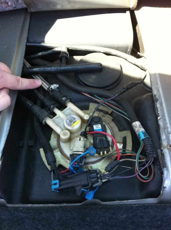
Here are a few pics I took the other day:
Here is the pump itself and I'm pointing to thd added braided line that I believe is the return
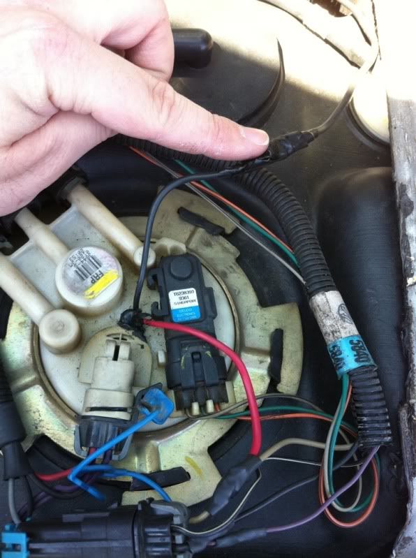
Here is what I believe is the ground for the second pump
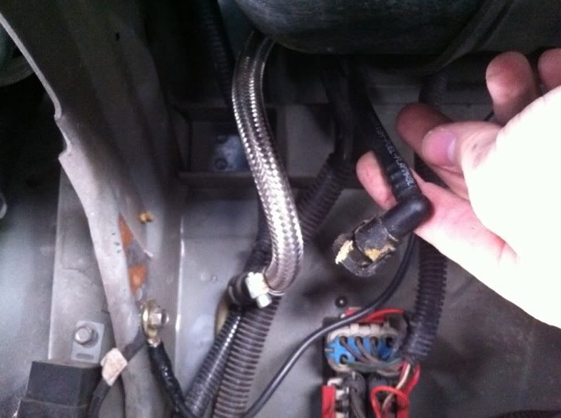
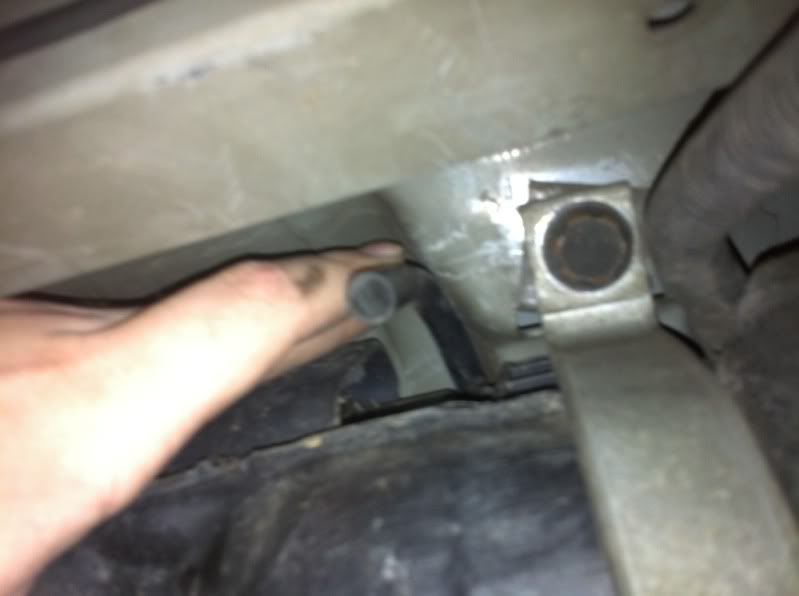
Here is the other end of the braided line that connects to the stock hard line under the car. There is a stock line hanging down that I believe is the other end of the evap. You can also see where that new ground connects.
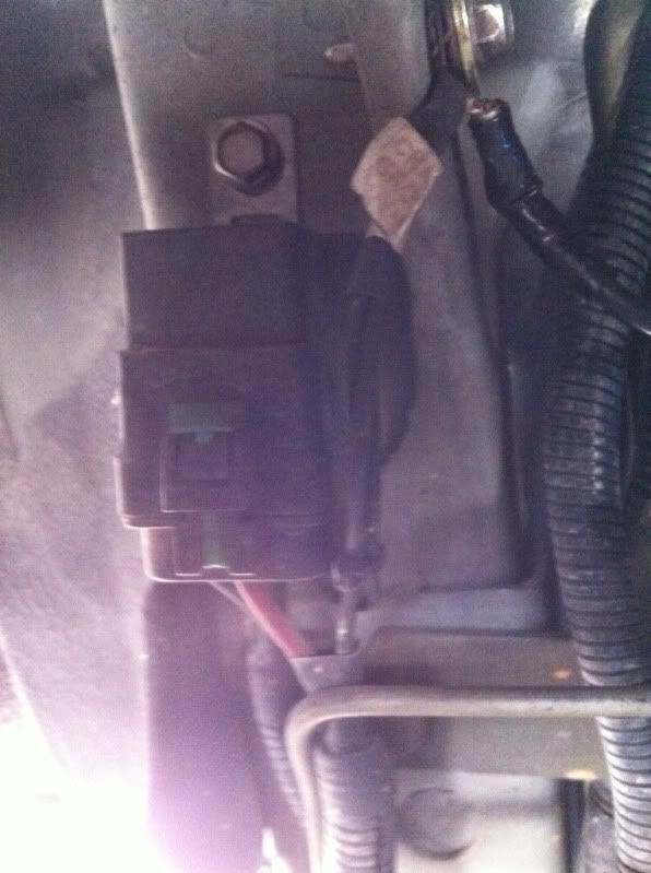
On the left of all that, you can see this relay, but I don't know if it's stock or added
What I'm wondering is that if that evap line goes back on the stock hard line at the bottom of the car where the braided line is connected now, then what line goes back into that 3rd port on the pump itself where the other side of the braided line is now connected?
Here is the pump itself and I'm pointing to thd added braided line that I believe is the return
Here is what I believe is the ground for the second pump
Here is the other end of the braided line that connects to the stock hard line under the car. There is a stock line hanging down that I believe is the other end of the evap. You can also see where that new ground connects.
On the left of all that, you can see this relay, but I don't know if it's stock or added
What I'm wondering is that if that evap line goes back on the stock hard line at the bottom of the car where the braided line is connected now, then what line goes back into that 3rd port on the pump itself where the other side of the braided line is now connected?
05-09-2011, 05:54 PM
#4
TECH Resident
iTrader: (7)
Join Date: Apr 2007
Location: STL, Mo
Posts: 954
Likes: 0
Received 0 Likes
on
0 Posts
Pin B (gray wire) is power
Pin C (black wire) is ground
Pin A (purple wire) is signal wire from sending unit to pcm.
Pin D (black/white) is 5v ref. For sending unit.
Pin C (black wire) is ground
Pin A (purple wire) is signal wire from sending unit to pcm.
Pin D (black/white) is 5v ref. For sending unit.
05-09-2011, 08:01 PM
#5
TECH Enthusiast
Thread Starter
iTrader: (54)
Join Date: Jul 2007
Location: Memphis, TN
Posts: 669
Likes: 0
Received 0 Likes
on
0 Posts
I guess it safe to assume then that the red and black wires coming up out of the hole in the center of the pump assembly with the black "goop" around it are added on strictly for the second pump then, correct?
Did you ever find those diagrams? I'm having more trouble figuring out what line goes back into that 3rd port than anything else now.
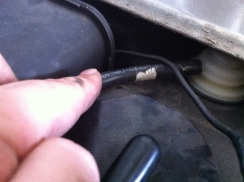
Is this line here strictly a vent tube or is something supposed to connect to it?:
This is where that line goes to at the top of the tank, connected to a plastic piece on the far right:
Did you ever find those diagrams? I'm having more trouble figuring out what line goes back into that 3rd port than anything else now.
Is this line here strictly a vent tube or is something supposed to connect to it?:
This is where that line goes to at the top of the tank, connected to a plastic piece on the far right:
Trending Topics
06-15-2015, 10:09 AM
#9
TECH Apprentice
Join Date: May 2010
Posts: 361
Likes: 0
Received 0 Likes
on
0 Posts
I don't remember where I downloaded it from but there is the gm service manuals on line that u can DL i bookmarked the site but I'm on my phone right now it's on my laptop Ill look when I get off work n post it
06-15-2015, 03:42 PM
#10
TECH Apprentice
Join Date: May 2010
Posts: 361
Likes: 0
Received 0 Likes
on
0 Posts
heres the link for the factory service manuals
https://www.mediafire.com/?40mfgeoe4ctti
hope that helps
https://www.mediafire.com/?40mfgeoe4ctti
hope that helps