OptiSpark Overhaul…. Help, PLEASE!!!
 05-24-2012, 04:45 AM
#1

Ok guru's, got me a little problem with my opti- dist.
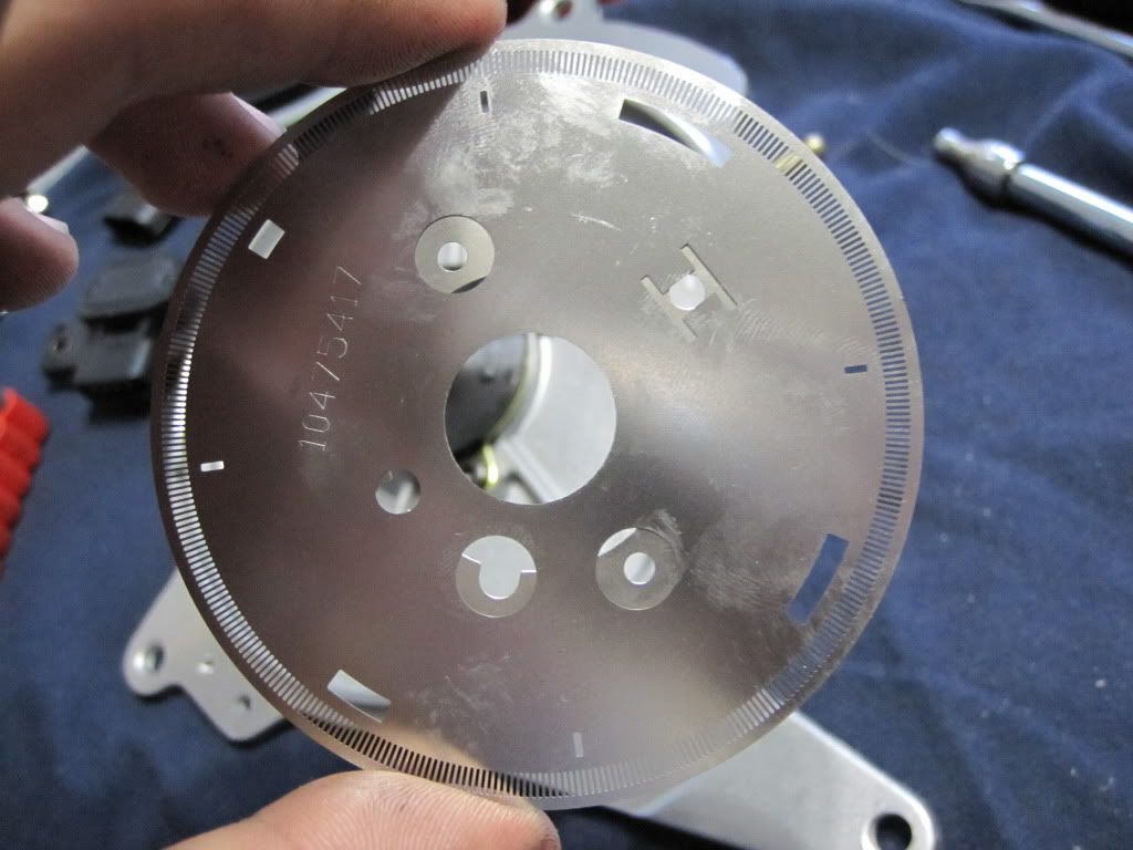
Whilst changing the cap and rotor on my vented style distributor, I had noticed a small amount of oil on the inside near the module and on the sensor wheel. I did a small lateral test of the bearing, and felt that it could use replacing.
Now, this is where everything goes sour! after removing the hub from the shaft, i had noticed that there is NO index for the hub to be aligned to. When reinstalling the hub, there is from what i calculate, up to 360 different settings for that hub. Knowing that there truly is only one, there is no indication as to where the proper one is located. On the rear of the dist(cam side) there is casted numbers indicating cylinder one and six top center, but no indicators on the inside to mark where the disk should point. To make things even harder on me, i have not been able to dig up ANY information as to the assembly process. I know that it is a critical(assuming) setting as to the timing of the reference point for cylinder number one fire. I have tried many close approximate settings with different outcomes. Detonation if too advanced, and poor performance too retarded. I have made a pointer, and set a mark on the damper to indicate TDC. Using a Snap-On brick, I have tried to set (as close as possible) the timing to correspond to what the reading on the scanner indicates. With the constant fluctuations of the computer adjusting timing, it is rater difficult to get a setting that the car 'likes'.
My question is, what is the proper way to set the indexing of the hub to the spindle to get the timing set correct.
I would hope that the answer doesn't come in the form of having to replace the unit. It would be a shame to have to spend undue amounts just to replace a $6 bearing. The cap and rotor replacement is bad enough!!
Thanx all.
p.s. love the site!!
 05-24-2012, 07:30 AM
#3
Ok guru's, got me a little problem with my opti- dist.
Whilst changing the cap and rotor on my vented style distributor, I had noticed a small amount of oil on the inside near the module and on the sensor wheel. I did a small lateral test of the bearing, and felt that it could use replacing.
Now, this is where everything goes sour! after removing the hub from the shaft, i had noticed that there is NO index for the hub to be aligned to. When reinstalling the hub, there is from what i calculate, up to 360 different settings for that hub. Knowing that there truly is only one, there is no indication as to where the proper one is located. On the rear of the dist(cam side) there is casted numbers indicating cylinder one and six top center, but no indicators on the inside to mark where the disk should point. To make things even harder on me, i have not been able to dig up ANY information as to the assembly process. I know that it is a critical(assuming) setting as to the timing of the reference point for cylinder number one fire. I have tried many close approximate settings with different outcomes. Detonation if too advanced, and poor performance too retarded. I have made a pointer, and set a mark on the damper to indicate TDC. Using a Snap-On brick, I have tried to set (as close as possible) the timing to correspond to what the reading on the scanner indicates. With the constant fluctuations of the computer adjusting timing, it is rater difficult to get a setting that the car 'likes'.
My question is, what is the proper way to set the indexing of the hub to the spindle to get the timing set correct.
I would hope that the answer doesn't come in the form of having to replace the unit. It would be a shame to have to spend undue amounts just to replace a $6 bearing. The cap and rotor replacement is bad enough!!
Thanx all.
p.s. love the site!!
 05-24-2012, 01:30 PM
#5
Thanx guys, but it isn't the disks to hub alignment that concerns me. It is more so the spindle that engages the camshaft, to the hub that the disks and rotor are mounted to that I'm having troubles with. Sorry if i was a little unclear as to what section I am working with.
05-24-2012, 01:38 PM
#6
TECH Fanatic
Join Date: Jan 2004
Location: Kingfisher Oklahoma
Posts: 1,157
Likes: 0
Received 0 Likes
on
0 Posts

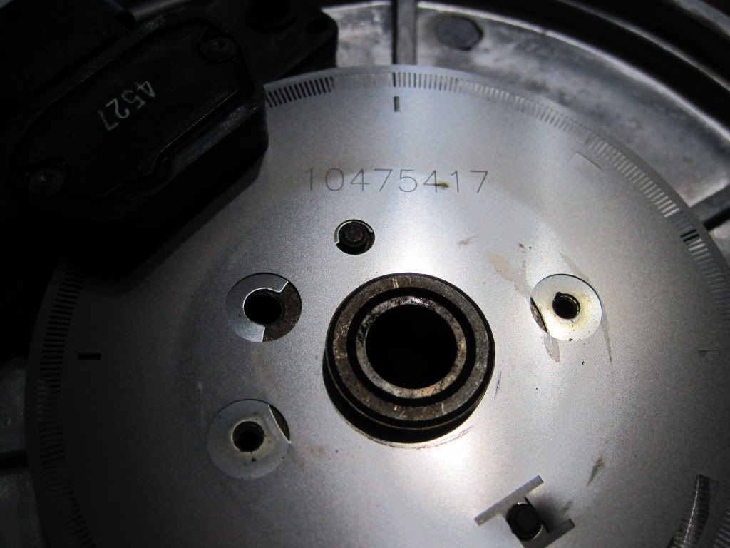
Am I correct in assuming that the shaf was pressed out through the back adn the hub in the pucture above has no inex on how it is aligned when pressed back together?
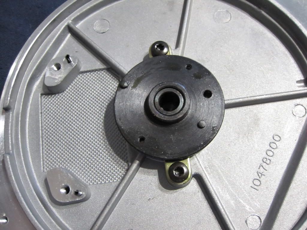
If so I guess you need a picture of front and back with detail on how the flange that mates to the camshaft is in relation to the flange that the thin stainless disc sets on, correct?
If so I guess you need a picture of front and back with detail on how the flange that mates to the camshaft is in relation to the flange that the thin stainless disc sets on, correct?
05-24-2012, 02:26 PM
#7
Am I correct in assuming that the shaf was pressed out through the back adn the hub in the pucture above has no inex on how it is aligned when pressed back together?
If so I guess you need a picture of front and back with detail on how the flange that mates to the camshaft is in relation to the flange that the thin stainless disc sets on, correct?
If so I guess you need a picture of front and back with detail on how the flange that mates to the camshaft is in relation to the flange that the thin stainless disc sets on, correct?
So it appears that it is fairly critical to its alignment. Whether or not it needs to be 'dead on', will hopefully soon no longer be one of lifes little mysteries.
Trending Topics
05-24-2012, 02:54 PM
#8
TECH Fanatic
Join Date: Jan 2004
Location: Kingfisher Oklahoma
Posts: 1,157
Likes: 0
Received 0 Likes
on
0 Posts
Unfortunately I am at work and do not have access to an opti to photograph.
Whats funny is I looked over my first post that was quoted, i made so many typing errors it's funny...lol
Whats funny is I looked over my first post that was quoted, i made so many typing errors it's funny...lol
05-28-2012, 01:50 AM
#9
Ok, i've come to the point of hair pulling. If at all possible, is there anyone who may be able to post a picture of their opti- without the cap installed and #1 TDC. I would be most appreciative. I am at whits end of timing the rotor to the cam hub after disassembling not knowing that there was NO index mark.
Please, all i am asking is a pic with the engine at #1 TDC showing the position of the rotor.
I have searched the W.W.W. with no results. I may not be typing my search words correctly, but still am unable to locate anything to help.
Thanx to the one to help ahead of time.
Please, all i am asking is a pic with the engine at #1 TDC showing the position of the rotor.
I have searched the W.W.W. with no results. I may not be typing my search words correctly, but still am unable to locate anything to help.
Thanx to the one to help ahead of time.
05-28-2012, 07:32 AM
#10
If you reassemble the hub and you're off even just slightly, engine performance will be affected.
While trying to replace the bearing yourself is a noble quest and something I might have also tried, it's just easier to buy a new unit and know it's dead on.
While trying to replace the bearing yourself is a noble quest and something I might have also tried, it's just easier to buy a new unit and know it's dead on.
05-28-2012, 02:10 PM
#11
It is starting to look like it is a mortal sin to even undertake such a task. I understand the consequences of having the setting 'a little off', but gee folks, at least get me into the ball park so that i can get to an outlet where i can get a new or even used distributor. being six miles from the hiway, and four miles off the grid, makes things a bit difficult. heck, i have to run a generator just to write this thread.
08-30-2012, 02:02 PM
#12
i really enjoy reading about everyones success stories here, for it has helped me in my quest for knowledge. I am still quite baffled about how difficult it has been in acquiring a little assistance on how to re-index the drive hub to reflector wheel on my opti-. I know that it would be in my best interest to just go out and spend the little cash i have on a new billet dist., but with the way things are, it really isn't an option. so far, i have gone so far as to run the engine without a water pump, and the distributor loose to try and find a 'sweet-spot' to where the engine performs the best. unfortunately, i can only run it for short periods for it warms rather quickly and it has varied results. like restarting after letting cool to day temps and having varied effects on my starter(like nearly breaking the nose cone off from kick-backs…ouch!).
i have noticed certain markings on the dist. housing, but am uncertain as to accuracy for as i don't have ANY guidelines as to what to line up.
if anyone in a current build that has a dist. with the cap off that could time their crankshaft 0* TDC then show a picture of the relative position of the rotor, i feel that it would help IMMENSELY in my quest to be 'on time' so to say, and possibly others.
thanx to those that can help.
kenski
08-30-2012, 08:14 PM
#15
I have totally disassembled the opti myself and replaced the bearing but you MUST scribe and indexing mark prior to taking the main shaft apart. I would find a busted opti on the board and refer to it and jig it up to ensure your good one goes back together right. I assume if its off even few degrees, it will act up.
08-31-2012, 07:36 PM
#17
TECH Veteran
That's the best I can do. I took that pic for someone that was making a rear mount opti and needed to know the position at #1. Whether it is mounted on the car or not is not going to make any difference.
09-14-2012, 02:27 AM
#18
thank you all for the relies. unfortunately it will, would, and does make a difference if the distributor is mounted to find the location of the reflector disc in my situation. as it stands, the main reason that it does matter if it is mounted(with the camshaft and crankshaft set at TDC 0*), is that THERE IS NO RELATED INFO as to the distributor-to-camshaft drive hub relationship to the mounting flange of the reluctor sound disc-to-optic-drive number one firing position. if this sounds like TOO MUCH info for the average person, i truly think that GM REALLY F>U> in the construction of this so called 'perfect timing device'. WHY IS IT THAT IT IS, AND HAS BECOME A MAJOR F…… DEAL TO SET THIS P.O.S TO ITS PROPER POSITION!!!!!!!
i really don't want to bore anyone more than i already have trying to do this 'somewhat simple' adjustment, but i may be only speaking for myself when i say ' I DON'T HAVE THE F……. EXTRA MONEY TO SPEND BECAUSE OF THINGS LIKE $4.65 GALLON FOR GAS, AND BLAH, BLAH, BLAH………'.
i guess i was hoping for was that i could find someone that could help with what i thought would be a simple request.
had i known that it would cost me two starters and so much stress, i would have just bought a ford
09-16-2012, 02:46 PM
#20
the rotor indeed points to number one regardless of whether or not it is mounted on the reflector disc or not, but when it is mounted to the engine - ANYWHERE the the camshaft is located out of 720* of camshaft position, the rotor-to-reluctor mounting flange does and is infinitely variable to the drive flange hub of the camshaft.
if there is anyone who does not understand what i am trying to describe, just remove the reflector hub from the distributor drive hub. i don't want to come off sounding like an ***, but there is NO index point for reference unless indexed before disassembly.
i know it sounds like a stupid question, but i want to be able to save someone the hassle of dealing with what i have over all this for the last TWO YEARS!!!!!
again, please, i know that i could just get a new distributor and have all this done with, but it has become an obsession and not just a simple tune-up.
still, thanx to all that are willing to help with my dilemma .