

Rod bolt install write-up
 03-13-2007, 05:00 PM
#1
TECH Addict
Thread Starter
iTrader: (28)
Join Date: Sep 2002
Location: Central Texas
Posts: 2,170
Likes: 0
Received 0 Likes
on
0 Posts

I figured since I couldn't find a write-up with pictures, that I'd take it up for anyone that is looking to do this in the future. Disclaimer: I am not responsible for any damage done to your car, use this write-up at your own discretion. Ok, on to the write-up. 
First thing you want to do is get your car up on jack stands and remove the front wheels and drain your oil. Be sure you disconnect your battery and choke the rear wheels, safety first!
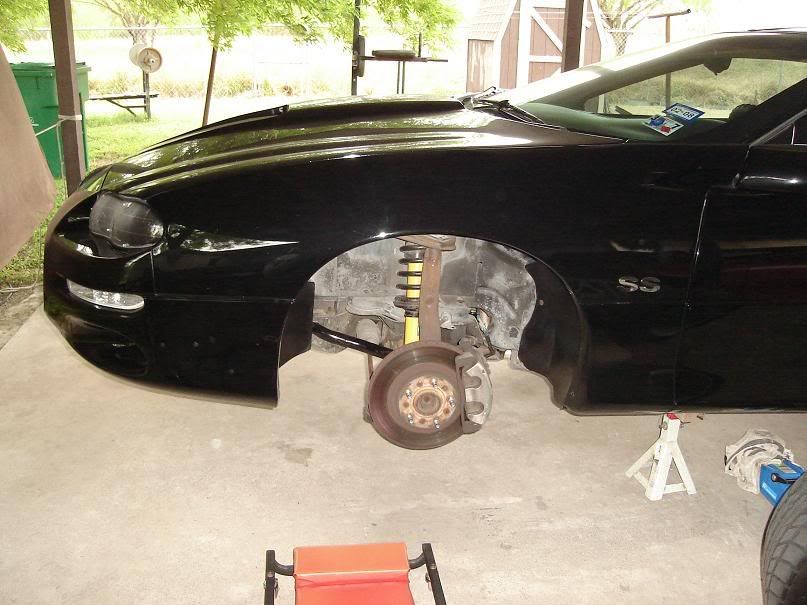
You�ll need to remove your serpentine belt in order to turn the crank over later in the install. The A/C belt can stay.
Next, loosen the bolts (13mm & 15mm) holding the front shocks to the lower A-arms and also loosen the end links holding the sway bar.
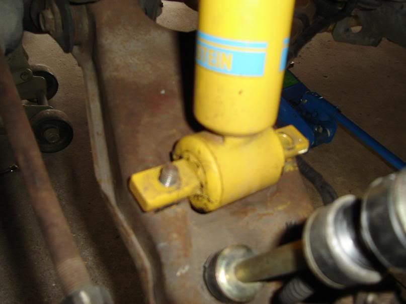
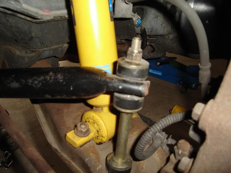
You�ll also need to loosen the bolt holding the spindle to the upper A-arm (15mm nut). Sorry, no pic of that. Be sure to support the lower A-arm so that the brake line isn�t ruptured. I used a zip-tie and some rope to tie the brake caliper to the spring. This kept the lower A-arm assembly from dropping too much and put no stress on the brake line.
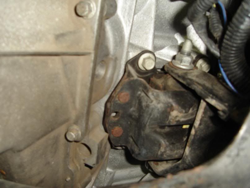
Next up is loosening the motor mounts. It helps to jack the engine up just a little bit to remove tension on the bolts so they can be a little easier to get out. First, loosen the nut holding the transmission mount to the transmission cross-member. It should be an 18mm nut if you�re using the stock unit. This will allow you to raise the engine/transmission a bit. You�ll have to jack the engine up, I used a piece of 2x4 and placed my jack where the transmission bolts on to the bellhousing. Now it�s time to move to the motor mounts. Here is a pic of the driver�s side motor mount.
Use an 18mm socket or wrench to loosen the nut. The bolt itself will eventually start to spin so you�ll have to hold it using another wrench/ratchet. Guess what though? The alternator is in the way! You guessed it, you�ll have to unbolt the alternator from the block. Doing this isn�t terribly difficult. You�ll need to unbolt the 3 15mm bolts on the front side of the alternator, and a 13mm bolt that�s hiding on the backside. Just feel around for it and you�ll find it. Once the four bolts are loosened, just set aside the alternator so it won�t bother you. I didn�t fully remove it, I simply worked around it and didn�t have any trouble. With the alternator out of the way, now you can remove the bolt holding the driver�s side motor mount to the K-member.
First thing you want to do is get your car up on jack stands and remove the front wheels and drain your oil. Be sure you disconnect your battery and choke the rear wheels, safety first!
You�ll need to remove your serpentine belt in order to turn the crank over later in the install. The A/C belt can stay.
Next, loosen the bolts (13mm & 15mm) holding the front shocks to the lower A-arms and also loosen the end links holding the sway bar.
You�ll also need to loosen the bolt holding the spindle to the upper A-arm (15mm nut). Sorry, no pic of that. Be sure to support the lower A-arm so that the brake line isn�t ruptured. I used a zip-tie and some rope to tie the brake caliper to the spring. This kept the lower A-arm assembly from dropping too much and put no stress on the brake line.
Next up is loosening the motor mounts. It helps to jack the engine up just a little bit to remove tension on the bolts so they can be a little easier to get out. First, loosen the nut holding the transmission mount to the transmission cross-member. It should be an 18mm nut if you�re using the stock unit. This will allow you to raise the engine/transmission a bit. You�ll have to jack the engine up, I used a piece of 2x4 and placed my jack where the transmission bolts on to the bellhousing. Now it�s time to move to the motor mounts. Here is a pic of the driver�s side motor mount.
Use an 18mm socket or wrench to loosen the nut. The bolt itself will eventually start to spin so you�ll have to hold it using another wrench/ratchet. Guess what though? The alternator is in the way! You guessed it, you�ll have to unbolt the alternator from the block. Doing this isn�t terribly difficult. You�ll need to unbolt the 3 15mm bolts on the front side of the alternator, and a 13mm bolt that�s hiding on the backside. Just feel around for it and you�ll find it. Once the four bolts are loosened, just set aside the alternator so it won�t bother you. I didn�t fully remove it, I simply worked around it and didn�t have any trouble. With the alternator out of the way, now you can remove the bolt holding the driver�s side motor mount to the K-member.
 03-13-2007, 05:01 PM
#2
TECH Addict
Thread Starter
iTrader: (28)
Join Date: Sep 2002
Location: Central Texas
Posts: 2,170
Likes: 0
Received 0 Likes
on
0 Posts
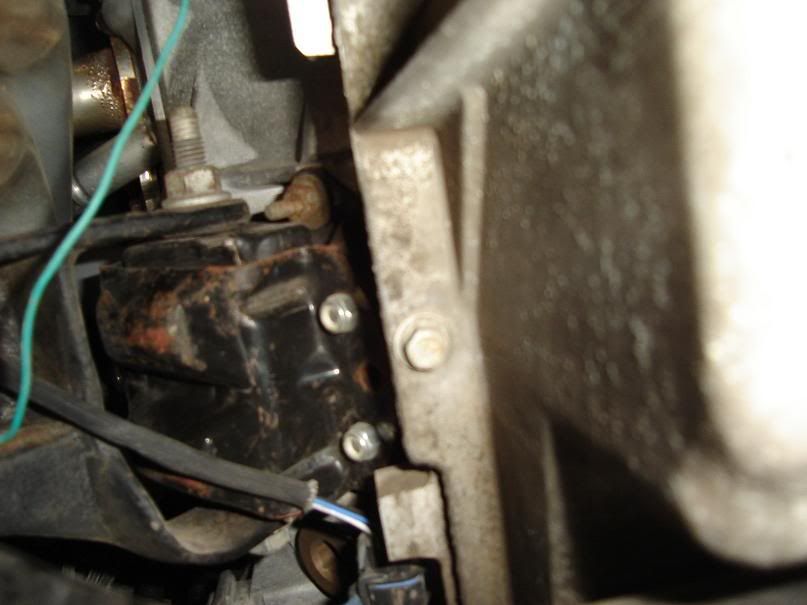
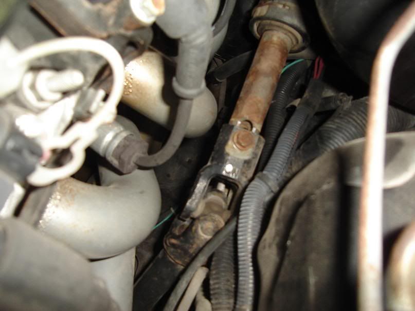
Now you can move onto the passenger motor mount. Before you can even see the motor mount, you must drop the starter. It�s held on to the block by two 13mm bolts, then two wires connected to it (8mm & 13mm). Remove the two 13mm bolts and the two wires running to the starter, along with the dust cover that�s located on the front side of the bellhousing (10mm bolt). Here are a couple of pics of the starter and the bolts holding it to the block.
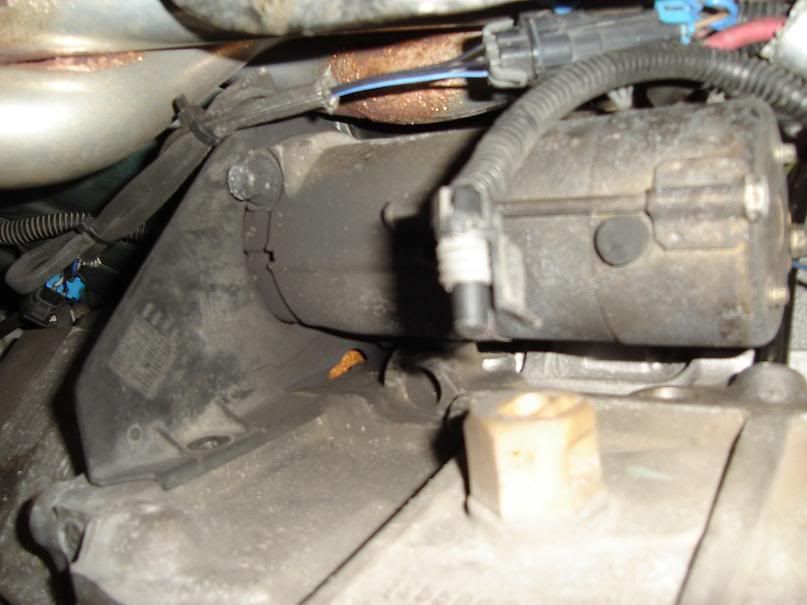
I had some trouble with this side, in order to remove the bolt running through the center of the mount, you have to remove the A/C compressor, then you�d have to deal with recharging the system once you�re done. I decided not to mess with that, so I unbolted the motor mount from the block itself. Here�s a pic of the motor mount.
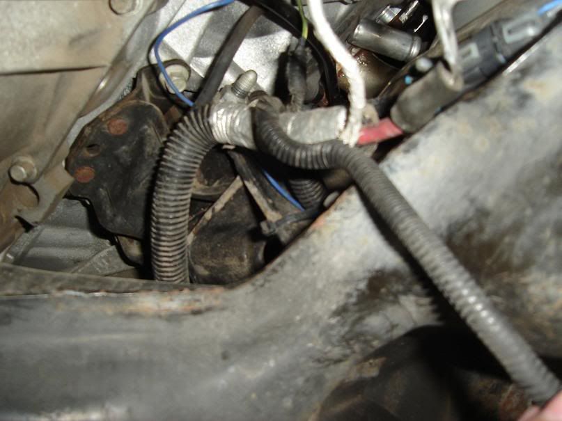
Looks pretty messy, huh? To get a better view, and move some clutter out of the way, I unbolted the ground that is running to the block (15mm bolt).
Move the wires out of the way and enjoy the clear view of the motor mount.
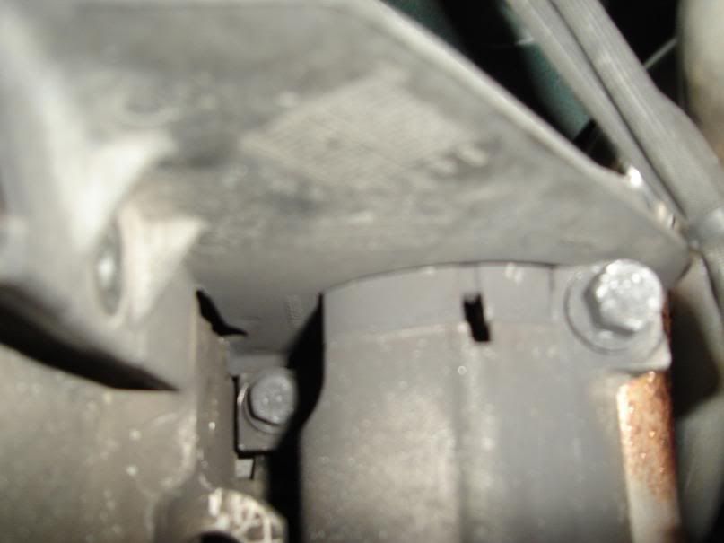
Now it looks easier to remove the 4 13mm bolts holding the motor mount clam shell to the block (noticed I said LOOKS easier). A swivel joint will help out a good bit here and save you from cursing the heavens.
Once you have all 4 bolts removed, we can move onto unbolting the steering linkage. This isn�t as hard as I thought it would be, I just loosened one 11mm bolt which you can reach from the engine bay with a long extension.
I had some trouble with this side, in order to remove the bolt running through the center of the mount, you have to remove the A/C compressor, then you�d have to deal with recharging the system once you�re done.
I decided not to mess with that, so I unbolted the motor mount from the block itself. Here�s a pic of the motor mount.Looks pretty messy, huh? To get a better view, and move some clutter out of the way, I unbolted the ground that is running to the block (15mm bolt).
Move the wires out of the way and enjoy the clear view of the motor mount.
Now it looks easier to remove the 4 13mm bolts holding the motor mount clam shell to the block (noticed I said LOOKS easier). A swivel joint will help out a good bit here and save you from cursing the heavens.
Once you have all 4 bolts removed, we can move onto unbolting the steering linkage. This isn�t as hard as I thought it would be, I just loosened one 11mm bolt which you can reach from the engine bay with a long extension.
03-13-2007, 05:03 PM
#3
TECH Addict
Thread Starter
iTrader: (28)
Join Date: Sep 2002
Location: Central Texas
Posts: 2,170
Likes: 0
Received 0 Likes
on
0 Posts
Ok, now that you�ve loosened both motor mounts, the steering linkage, the socks, spindles and sway bar, we can move onto lowering the K-member. 
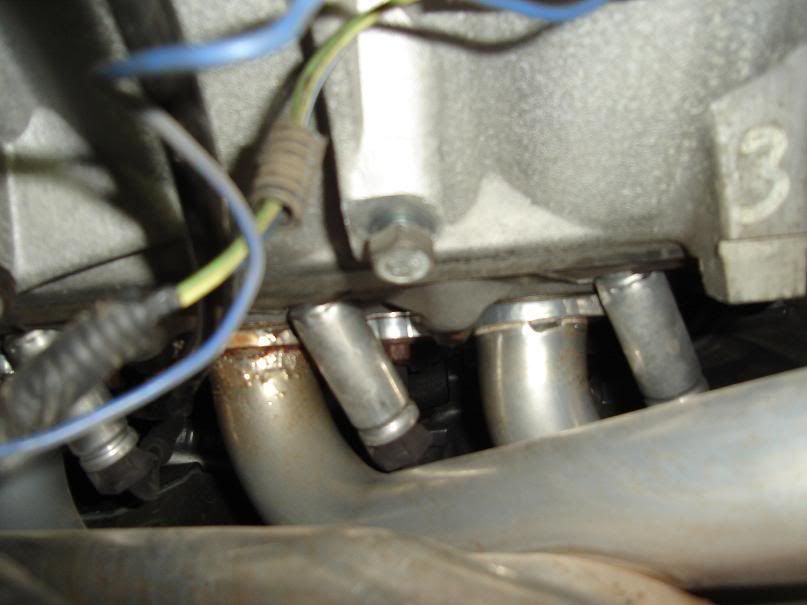
This is basically what I wanted to know when looking around for a write-up, where to unbolt the K-member from the frame. Well, here it is. There are a total of 6 bolts holding the K-member to the frame of your f-body (all 18mm). Here are a couple of pics showing the three driver�s side bolts.
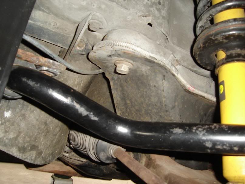
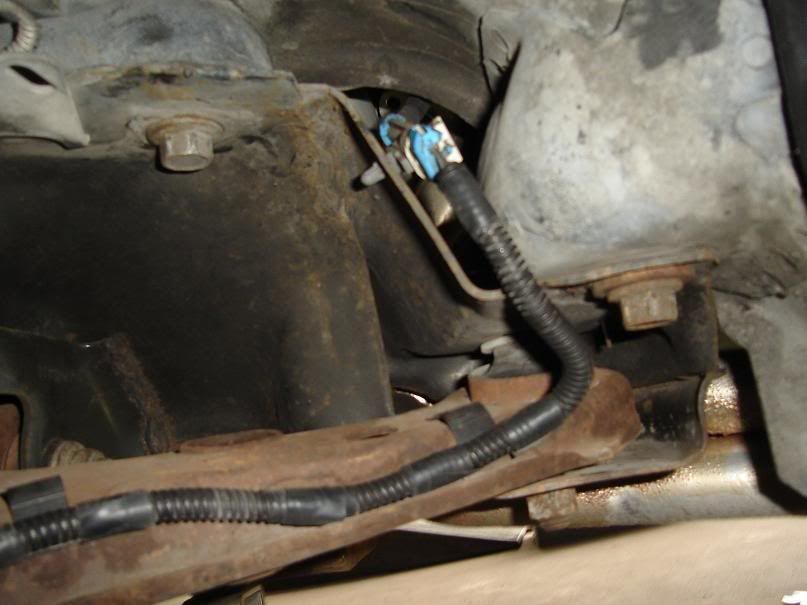
Before you go and loosen these bolts, be sure your K-member is supported by a jack or two. You�ll need to break out your breaker bar and use a little muscle to break these bolts loose, so put some back into it. With these bolts out of the way, the K-member should drop. I had to give it some encouraging whacks with a rubber mallet in order for mine to drop, but it got there. I decided not to completely drop it.
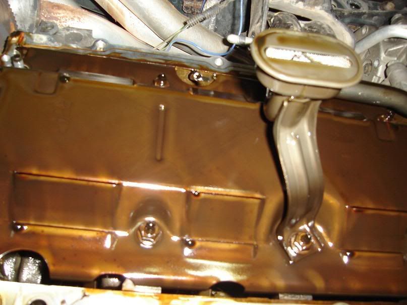
With the K-member lowered, we can now move onto the oil pan bolts. There are about 13 10mm bolts holding the pan to the block and two 15mm bolts holding the pan to the bellhousing. Loosen and remove all of these bolts and your oil pan should drop out the back. You�ll need to maneuver it to get it out all the way and maybe adjust the height of the K-member/engine, but it will come out. Once you have the pan off, you�ll have a clear view of the pick up tube and the crank oil deflector pictured below.
This is basically what I wanted to know when looking around for a write-up, where to unbolt the K-member from the frame. Well, here it is. There are a total of 6 bolts holding the K-member to the frame of your f-body (all 18mm). Here are a couple of pics showing the three driver�s side bolts.
Before you go and loosen these bolts, be sure your K-member is supported by a jack or two. You�ll need to break out your breaker bar and use a little muscle to break these bolts loose, so put some back into it. With these bolts out of the way, the K-member should drop. I had to give it some encouraging whacks with a rubber mallet in order for mine to drop, but it got there. I decided not to completely drop it.
With the K-member lowered, we can now move onto the oil pan bolts. There are about 13 10mm bolts holding the pan to the block and two 15mm bolts holding the pan to the bellhousing. Loosen and remove all of these bolts and your oil pan should drop out the back. You�ll need to maneuver it to get it out all the way and maybe adjust the height of the K-member/engine, but it will come out. Once you have the pan off, you�ll have a clear view of the pick up tube and the crank oil deflector pictured below.
03-13-2007, 05:04 PM
#4
TECH Addict
Thread Starter
iTrader: (28)
Join Date: Sep 2002
Location: Central Texas
Posts: 2,170
Likes: 0
Received 0 Likes
on
0 Posts
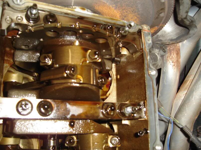
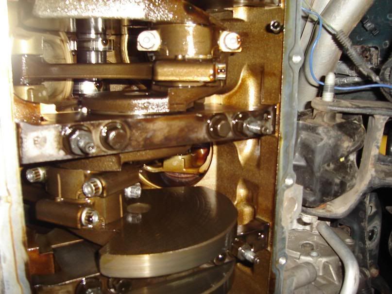
To remove this, you have to unbolt the pickup tube from the oil pump (10mm bolt) and unbolt the 13mm nut holding the pickup tube to the crank oil deflector. With the pickup tube out of the way, you can unbolt the remaining 7 13mm nuts holding the crank oil deflector. Remove the deflector plate and marvel at the rotating assembly of your LS1. 
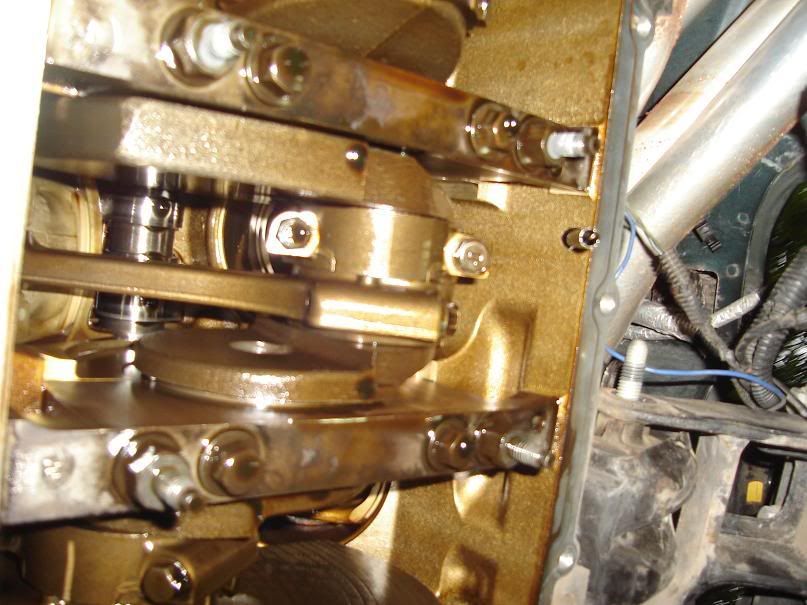
Now, we can finally swap out the rod bolts! Depending on what bolts you decided to use, the instructions will vary. Use the directions supplied by the bolt company. I went with Katech bolts, so it was pretty straightforward.
I removed one bolt at a time from each rod cap (did two at a time). In other words, make sure there is one bolt tightened on each rod cap at all times! Failing to do so will result in messing up your bearings. In some year LS1�s, there are ferrules in the bolt holes, which you absolutely must remove, otherwise you risk damage to your engine. For some reason, my engine did not come with these ferrules, so I simply removed the bolt and replaced it with a new one.
After removing the bolts, I lubed up the new Katech bolt threads and head with the assembly lube and torqued it down. I torqued the bolt down 3 times, twice at 30 lb/ft, then a final pass at 50 lb/ft. You�ll have to turn the crank over in order to reach some bolts, so just use a 24mm socket and a breaker bar to rotate it by hand accordingly.
03-13-2007, 05:04 PM
#5
TECH Addict
Thread Starter
iTrader: (28)
Join Date: Sep 2002
Location: Central Texas
Posts: 2,170
Likes: 0
Received 0 Likes
on
0 Posts
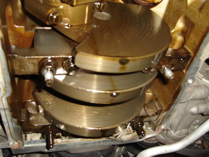
Here�s a pic of the finished product. Isn�t it beautiful? 
Once you�re done swapping out all the rod bolts, it�s time to put everything back together. Bolt the oil deflector plate on and torque the 8 bolts down to 18 lb/ft. Don�t forget the oil pickup tube! Be sure to put the oil pump O-ring on the pickup tube, which is a piece of cake doing it this way. With both of these back on, it�s time to bolt down the oil pan. First hand thread all bolts into the block, then torque the two 15mm bolts down to 35 lb/ft. Your pan should be aligned now, just torque down the remaining 10mm bolts. The rest is basically assembled in the reverse order of the tear down. Congratulations, you�ve completed a connecting rod bolt swap! Now you can spin your LS1 to the moon and be worry free! Well, maybe not to the moon, but you get the idea�
Once you�re done swapping out all the rod bolts, it�s time to put everything back together. Bolt the oil deflector plate on and torque the 8 bolts down to 18 lb/ft. Don�t forget the oil pickup tube! Be sure to put the oil pump O-ring on the pickup tube, which is a piece of cake doing it this way. With both of these back on, it�s time to bolt down the oil pan. First hand thread all bolts into the block, then torque the two 15mm bolts down to 35 lb/ft. Your pan should be aligned now, just torque down the remaining 10mm bolts. The rest is basically assembled in the reverse order of the tear down. Congratulations, you�ve completed a connecting rod bolt swap! Now you can spin your LS1 to the moon and be worry free!
Well, maybe not to the moon, but you get the idea�
03-13-2007, 05:09 PM
#6
TECH Resident
iTrader: (3)

Join Date: Sep 2005
Location: Edmond, Oklahoma
Posts: 796
Likes: 0
Received 0 Likes
on
0 Posts
Its cheap insurance to use a new pickup tube O-ring while you are in there and make doubly sure you haven't pinched it when you re-install the pickup tube.
Trending Topics
03-13-2007, 05:10 PM
#8
TECH Addict
Thread Starter
iTrader: (28)
Join Date: Sep 2002
Location: Central Texas
Posts: 2,170
Likes: 0
Received 0 Likes
on
0 Posts
Originally Posted by brad8266
You do not need to remove the AC compressor lines, just unbolt the compressor from the bracket and sit it on the swaybar. That way you can just take out the 18mm bolt in the motor mount.
 Now it should be finished.
  03-13-2007, 05:12 PM
#9
12 Second Club
iTrader: (49)

Join Date: May 2006
Location: College Station, Texas
Posts: 966
Likes: 0
Received 0 Likes
on
0 Posts
bad *** man...im considering rod bolts during my cam setup due to the weaker bolts on the 98's ive heard about...what exactly goes wrong with them when spun to high?
03-13-2007, 05:15 PM
#11
TECH Senior Member
iTrader: (23)
Join Date: Aug 2005
Location: Watertown, NY
Posts: 8,797
Likes: 0
Received 0 Likes
on
0 Posts
Originally Posted by Krab
Dammit, you beat me to posting the last two posts. Now it should be finished.
Now it should be finished. You do not need to remove the AC compressor lines, just unbolt the compressor from the bracket and tie it up somewhere. That way you can just take out the 18mm bolt in the motor mount. No need to undo the mount from the block.
03-13-2007, 05:15 PM
#12
TECH Fanatic
iTrader: (17)

Join Date: Sep 2006
Location: dayton ohio
Posts: 1,638
Likes: 0
Received 0 Likes
on
0 Posts
Originally Posted by brad8266
Cool write up, good job with the pics.
Sticky this for the millions of people that ask about changing rod bolts.
Sticky this for the millions of people that ask about changing rod bolts.
03-13-2007, 05:16 PM
#13
TECH Senior Member
iTrader: (23)
Join Date: Aug 2005
Location: Watertown, NY
Posts: 8,797
Likes: 0
Received 0 Likes
on
0 Posts
Originally Posted by connexion2005
bad *** man...im considering rod bolts during my cam setup due to the weaker bolts on the 98's ive heard about...what exactly goes wrong with them when spun to high?
03-13-2007, 05:25 PM
#16
TECH Addict
Thread Starter
iTrader: (28)
Join Date: Sep 2002
Location: Central Texas
Posts: 2,170
Likes: 0
Received 0 Likes
on
0 Posts
Originally Posted by john563
great write up and pics.How long did it take you start to finish?
thanks
john
thanks
john
brad8266: Good to know you don't have to completely remove the compressor, I'm sure that will come in handy for people who do this in the future.
Thanks for the props guys, it wasn't really easy doing this install by myself.

 03-13-2007, 06:10 PM
#19
TECH Fanatic
iTrader: (17)
Join Date: Sep 2006
Location: dayton ohio
Posts: 1,638
Likes: 0
Received 0 Likes
on
0 Posts
Originally Posted by Krab
From start to finish, it took me about 16 hours. Started it yesterday morning and finished today after lunch. Lowering the K-member gave me a hard time because I couldn't figure out what was holding the driver's side up. It ended up being the steering linkage.
brad8266: Good to know you don't have to completely remove the compressor, I'm sure that will come in handy for people who do this in the future.
Thanks for the props guys, it wasn't really easy doing this install by myself.
brad8266: Good to know you don't have to completely remove the compressor, I'm sure that will come in handy for people who do this in the future.
Thanks for the props guys, it wasn't really easy doing this install by myself.
