efi24x lt1 harness repin with PICS!
 04-25-2011, 10:39 PM
#1


I'm in the process of re-pinning my harness so I thought I'd try to get it all documented here. My harness I'm working with is a 96 and this is going into a 94, so it's going to be a little tricky. Couple of things before you get started.
One, familiarize yourself with the schematics for your car, your particular harness and the ls1 schematic. Also you must have a clear understanding of these connectors:
1)c100/c105 (c105 present in 95+cars) on right shock tower
2)c210/c220/c230 - inside car, passenger side (these 3 female connects go to your harness)
The above connectors bring power to your harness so it's crucial that you know exactly what they are and what their purpose is. The repin directions from EFI Connection only cover the PCM connectors, they don't get into the C connectors. For the C connectors, this is your friend here -> http://shbox.com/1/harness_connector_faces.htm. Just remember it's these C connectors that bring all the power to your harness, so you have to make sure they are pinned correctly to the PCM.
Now that we have the inventory of the schematics and the C connector layouts, we can proceed with the repin activities.
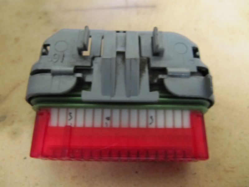
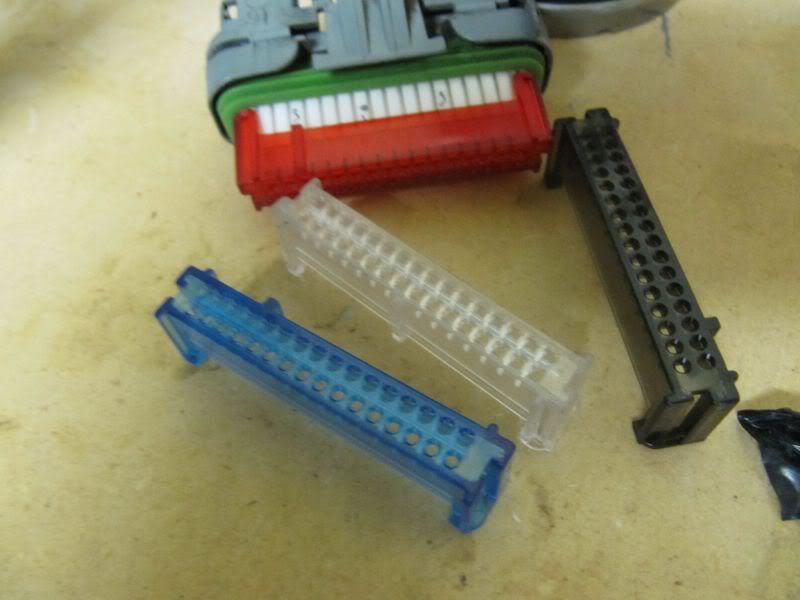
First thing I did was label my two PCM connectors for Red and Blue, not really necessary, but helped me so I wouldn't screw it up. I did this because the red/blue covers get installed at the end and this way I'll always know what they are until the last point. I don't want to install them sooner in case I need to take a wire out or I screw one up, this will be easier.
My approach on this is to get the PCM plugged in with all new things for the efi 24x connectors then I will wire in one lt1 connector (I'm calling the 4 main plugs into the PCM a connector) at a time. I will do each pin one at a time from each connector and hopefully not rush through this.
Now critical – don't forget LS1 firing order is different from LT1. LS1 = 1-8-7-2-6-5-4-3 and LT1 =1-8-4-3-6-5-7-2. Since you can't program for this, you have to swap the wires directly at the PCM. So that means where the LS1 harness says put in cylinder 7 (27), you would put in cylinder 4(29). That means cylinder 7 plugs into RED terminal 29 and cylinder 4 plugs into RED terminal 27. Do the same for cylinders 3 and 2.
The pin location I have below is how it should be plugged in to run a LT1. One thing efi doesn't have on their site is the colors of the harness and what represents each coil so I have added that here
A: Ignition Coil Harnesses:
1) Install the Bank 1 Coil harness. (This harness has 7 wires. 4 are for the coil control and the other 3 are for ground/low reference signal/and power)
Purple wire = Coil 1 = RED 26
Red wire = Coil 7 = RED 29
Lt Blue = Coil 3 = RED 67
Dk Green = Coil 5 = RED 68
and the low ref signal:
Brown wire = Bank 1 = RED 60
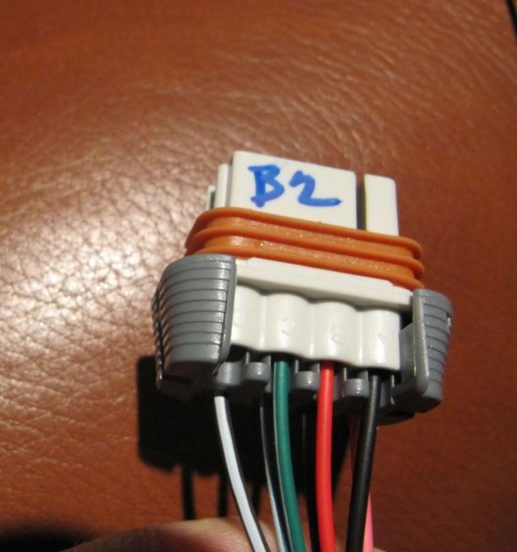
2) Install the Bank 2 Coil harness. (This also has 7 wires. 4 are for the coil control and the other 3 are for ground/low reference/and power) This harness should look exactly like the Bank1 harness except it will have a white stripe for the coils.
Purple/white =Coil 8 = RED 66
Red/white = Coil 2 = RED 69
Lt Blue/white = Coil 6 = RED 28
Dk Green/white = Coil 4 = RED 27
and the low ref signal:
Brown/white wire = Bank 2 = RED 61
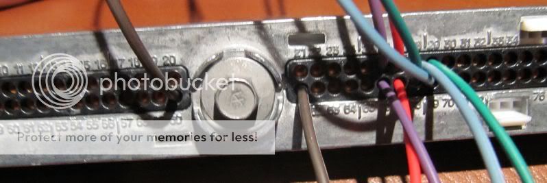
Here's the updated pic:
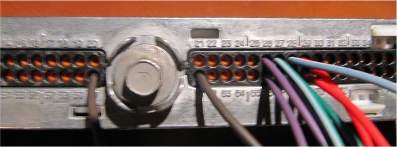
Once you get it all plugged in, you'll see how the wiring colors actually would have lined up for the LS1 firing order, but yours will have them off because of the swap for the firing order.
I labeled my bank 2 connector so i remember later and not screw it up when it's all loomed up.
more pics posts to follow as I go. won't be too quick but hopefully not too slow, want to get the car running again by mid May
One, familiarize yourself with the schematics for your car, your particular harness and the ls1 schematic. Also you must have a clear understanding of these connectors:
1)c100/c105 (c105 present in 95+cars) on right shock tower
2)c210/c220/c230 - inside car, passenger side (these 3 female connects go to your harness)
The above connectors bring power to your harness so it's crucial that you know exactly what they are and what their purpose is. The repin directions from EFI Connection only cover the PCM connectors, they don't get into the C connectors. For the C connectors, this is your friend here -> http://shbox.com/1/harness_connector_faces.htm. Just remember it's these C connectors that bring all the power to your harness, so you have to make sure they are pinned correctly to the PCM.
Now that we have the inventory of the schematics and the C connector layouts, we can proceed with the repin activities.
First thing I did was label my two PCM connectors for Red and Blue, not really necessary, but helped me so I wouldn't screw it up. I did this because the red/blue covers get installed at the end and this way I'll always know what they are until the last point. I don't want to install them sooner in case I need to take a wire out or I screw one up, this will be easier.
My approach on this is to get the PCM plugged in with all new things for the efi 24x connectors then I will wire in one lt1 connector (I'm calling the 4 main plugs into the PCM a connector) at a time. I will do each pin one at a time from each connector and hopefully not rush through this.
Now critical – don't forget LS1 firing order is different from LT1. LS1 = 1-8-7-2-6-5-4-3 and LT1 =1-8-4-3-6-5-7-2. Since you can't program for this, you have to swap the wires directly at the PCM. So that means where the LS1 harness says put in cylinder 7 (27), you would put in cylinder 4(29). That means cylinder 7 plugs into RED terminal 29 and cylinder 4 plugs into RED terminal 27. Do the same for cylinders 3 and 2.
The pin location I have below is how it should be plugged in to run a LT1. One thing efi doesn't have on their site is the colors of the harness and what represents each coil so I have added that here
A: Ignition Coil Harnesses:
1) Install the Bank 1 Coil harness. (This harness has 7 wires. 4 are for the coil control and the other 3 are for ground/low reference signal/and power)
Purple wire = Coil 1 = RED 26
Red wire = Coil 7 = RED 29
Lt Blue = Coil 3 = RED 67
Dk Green = Coil 5 = RED 68
and the low ref signal:
Brown wire = Bank 1 = RED 60
2) Install the Bank 2 Coil harness. (This also has 7 wires. 4 are for the coil control and the other 3 are for ground/low reference/and power) This harness should look exactly like the Bank1 harness except it will have a white stripe for the coils.
Purple/white =Coil 8 = RED 66
Red/white = Coil 2 = RED 69
Lt Blue/white = Coil 6 = RED 28
Dk Green/white = Coil 4 = RED 27
and the low ref signal:
Brown/white wire = Bank 2 = RED 61
Here's the updated pic:
Once you get it all plugged in, you'll see how the wiring colors actually would have lined up for the LS1 firing order, but yours will have them off because of the swap for the firing order.
I labeled my bank 2 connector so i remember later and not screw it up when it's all loomed up.
more pics posts to follow as I go. won't be too quick but hopefully not too slow, want to get the car running again by mid May
Last edited by merim123; 06-17-2013 at 09:30 PM. Reason: fixed errors
 04-25-2011, 10:40 PM
#2
After the correction in post #9 below, I took the rest of the operation to the garage. I printed these out and then started with the red connector on the LT1 and pinned it over to the Blue/Red as shown here:
http://www.eficonnection.com/coilper...ns_LS1_Red.jpg
http://www.eficonnection.com/coilper...s_LS1_Blue.jpg
One thing I noticed about these two guides is that they are as they need to be for the LT1 already, wish this was in excel format so I can customize it for my situation. maybe I'll do that here soon.
Here it is after I got the lt1 red connector done:
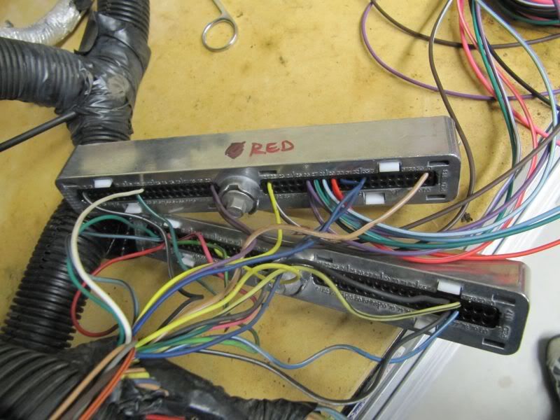
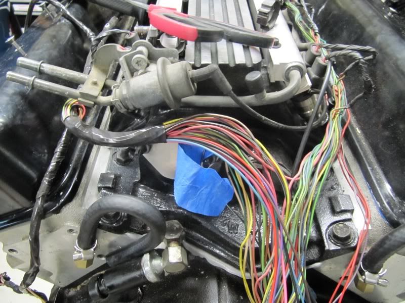
After repinning, there were still some connections left over in the harness that are no longer needed. I taped them off and labeled them so I don't forget later, but I will end up removing all the wires. Since my setup is a T56, I think I can get rid of all the 4l60e connections, but not sure if they are shared with anything on the t56 yet so I need to look through the manual just to be safe.
here's what was left from the red connector:
and this felt good, 1 down and 3 to go:
it felt so good though, that I kept on going and managed to get it all done in about one hour:
and now i have all the easy work done, looks rough in the pic, but not too bad at all:
So I got away from my original plan of doing all the new or added stuff first, but I think it's ok, because I get it more clearly now.
http://www.eficonnection.com/coilper...ns_LS1_Red.jpg
http://www.eficonnection.com/coilper...s_LS1_Blue.jpg
One thing I noticed about these two guides is that they are as they need to be for the LT1 already, wish this was in excel format so I can customize it for my situation. maybe I'll do that here soon.
Here it is after I got the lt1 red connector done:
After repinning, there were still some connections left over in the harness that are no longer needed. I taped them off and labeled them so I don't forget later, but I will end up removing all the wires. Since my setup is a T56, I think I can get rid of all the 4l60e connections, but not sure if they are shared with anything on the t56 yet so I need to look through the manual just to be safe.
here's what was left from the red connector:
and this felt good, 1 down and 3 to go:
it felt so good though, that I kept on going and managed to get it all done in about one hour:
and now i have all the easy work done, looks rough in the pic, but not too bad at all:
So I got away from my original plan of doing all the new or added stuff first, but I think it's ok, because I get it more clearly now.
Last edited by merim123; 04-26-2011 at 09:46 PM.
04-25-2011, 10:40 PM
#3
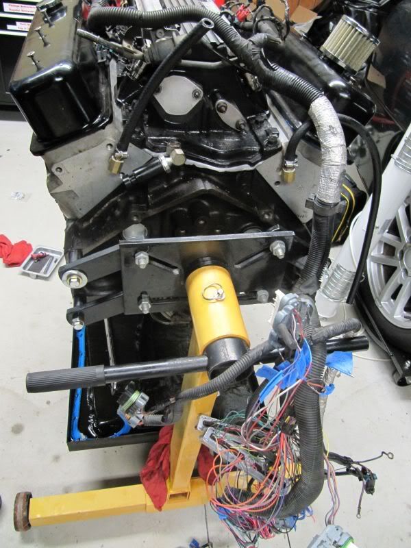
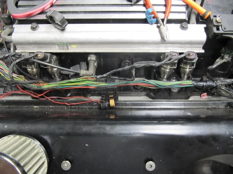
Made a little more progress tonight. Decided it was time to put the harness on the motor and get the injectors / maf /map sensor in place so that I can get the layout in the right place.
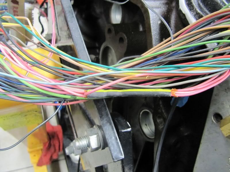
I then started stripping the loom and taking all the tape off, need to figure out where to go buy the electric tape like this but that doesn't have glue like electric tape, but it was all dry.
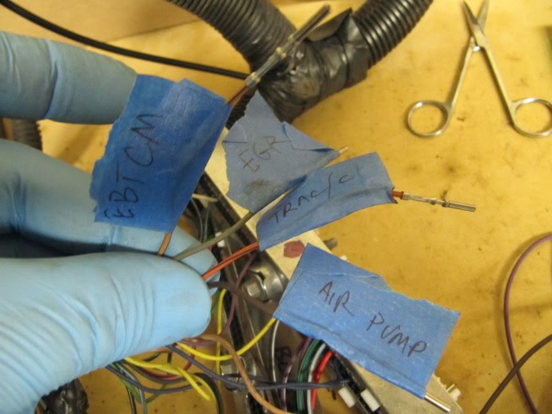
I was able to take out the EVAP and EGR connectors and traction control connectors. it's intimidating at first, but all you have to do is get one wire right at a time. I have some that are spliced like this that I will have to cut and cap off with some heat shrink so I don't have a short anywhere.
so still need to go chase some of the automatic trans pcm leads. Since my car is manual and staying manual, not sure why the lt1 manual harness has these in the pcm and the service manual says they are only for the auto trans. will keep going.
I then started stripping the loom and taking all the tape off, need to figure out where to go buy the electric tape like this but that doesn't have glue like electric tape, but it was all dry.
I was able to take out the EVAP and EGR connectors and traction control connectors. it's intimidating at first, but all you have to do is get one wire right at a time. I have some that are spliced like this that I will have to cut and cap off with some heat shrink so I don't have a short anywhere.
so still need to go chase some of the automatic trans pcm leads. Since my car is manual and staying manual, not sure why the lt1 manual harness has these in the pcm and the service manual says they are only for the auto trans. will keep going.
Last edited by merim123; 04-28-2011 at 11:14 PM.
04-25-2011, 10:40 PM
#4
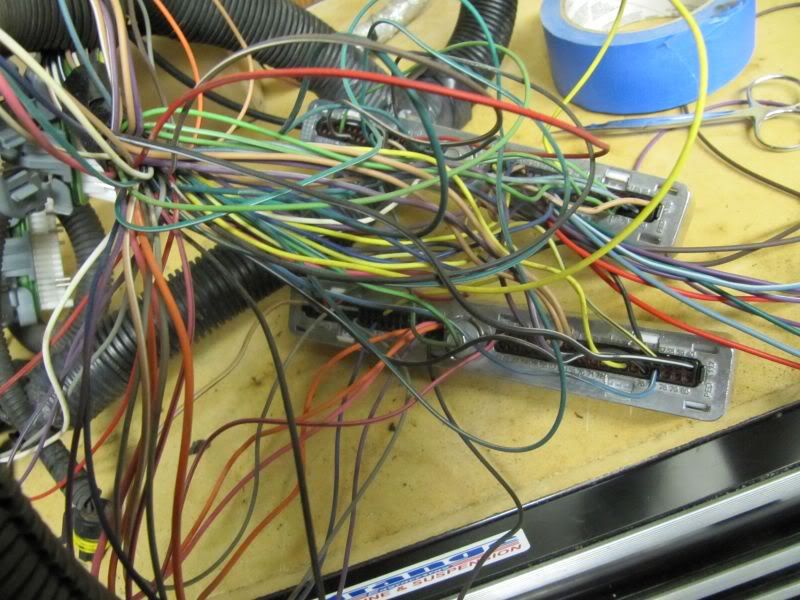
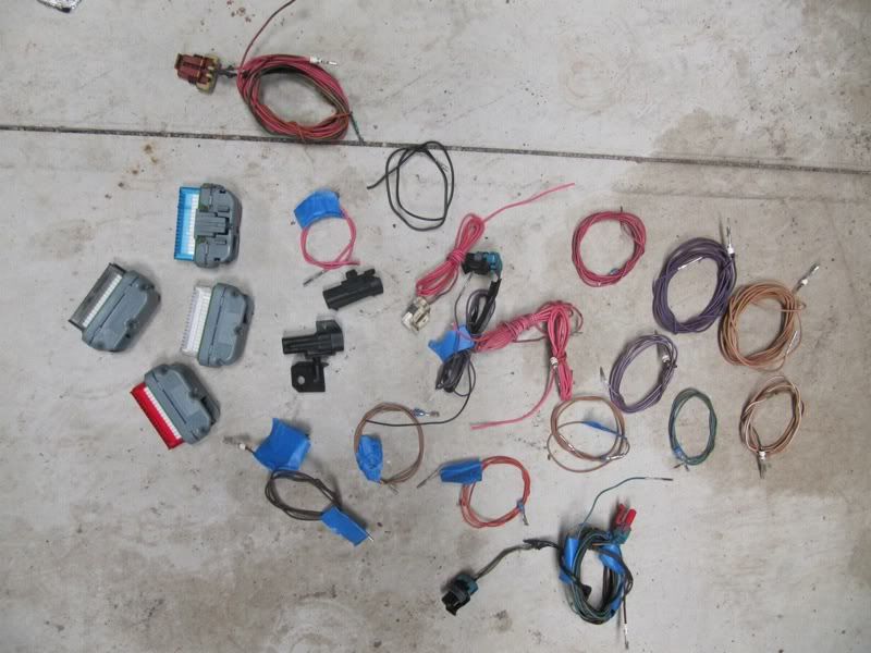
Finished chasing the rest of the wires and getting rid of them. This is everything I pulled out. I couldn't believe the pile but I did reuse some of the connectors for the crankshaft sensor and made sure I ran that correctly as well.
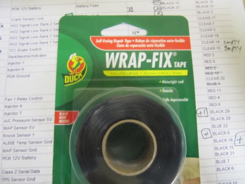
I then started cleaning and tightening the harness up and routing everything. I was looking locally for some non-adhesive tape and found this stuff at Menard's that should do the trick. I'm going to be using loom over this anyway but this stuff is pretty good. It really sticks to itself well but not anything else.
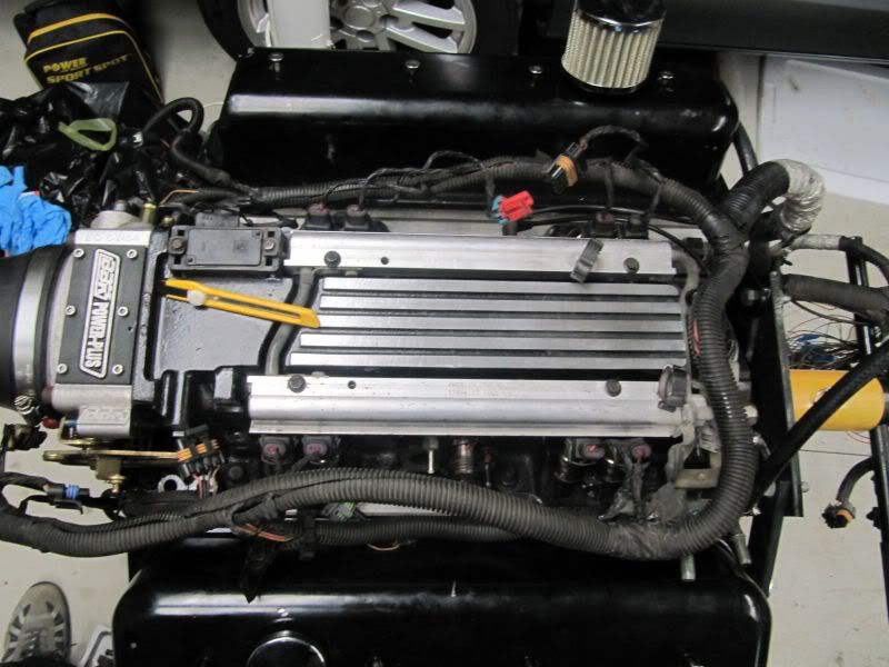
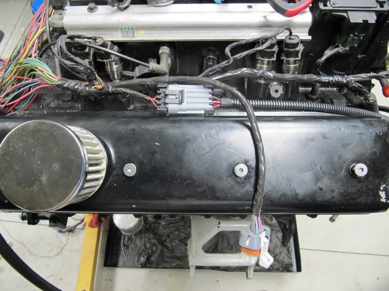
Then I started routing. I plugged all the sensors in to make sure I had good reach and started to do some quick small wraps to hold it and once it was held, i did the full wrap i wanted. Probably over did it a bit, but I like that it will look clean and I will put loom over it so this gives me a view of what it will look like with loom. Here's the first pass of the routing on the passenger side
And here it is buttoned up and tightened nicely. Finally starting to look like a harness again!
and the driver side
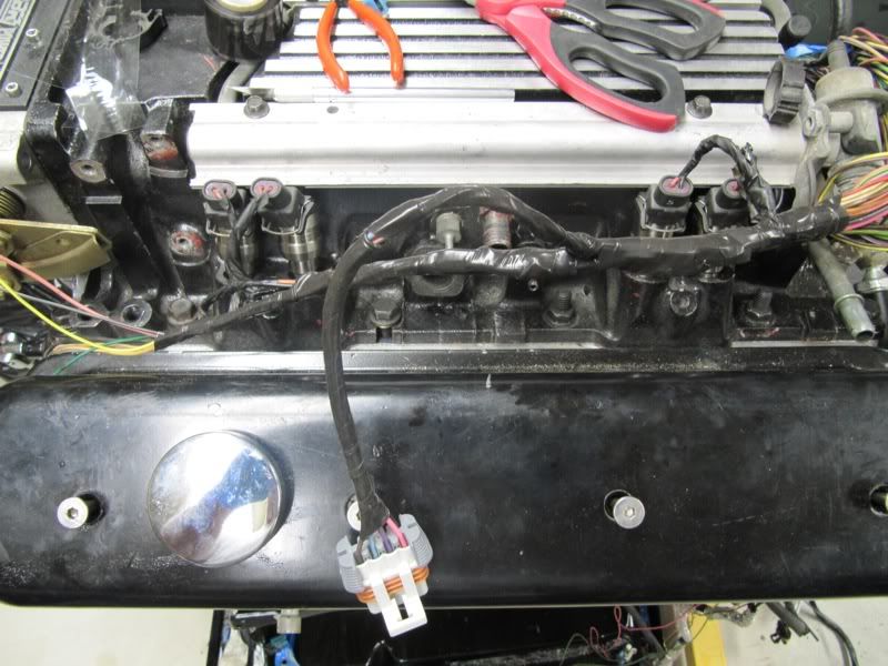
and from the rear with the driver side done first
I then started cleaning and tightening the harness up and routing everything. I was looking locally for some non-adhesive tape and found this stuff at Menard's that should do the trick. I'm going to be using loom over this anyway but this stuff is pretty good. It really sticks to itself well but not anything else.
Then I started routing. I plugged all the sensors in to make sure I had good reach and started to do some quick small wraps to hold it and once it was held, i did the full wrap i wanted. Probably over did it a bit, but I like that it will look clean and I will put loom over it so this gives me a view of what it will look like with loom. Here's the first pass of the routing on the passenger side
And here it is buttoned up and tightened nicely. Finally starting to look like a harness again!
and the driver side
and from the rear with the driver side done first
Last edited by merim123; 05-01-2011 at 06:24 PM.
04-25-2011, 11:19 PM
#7
Cool! Maybe if I decide to do it for my truck project I will just re-pin instead of springing for the harness. I know when I finished the Z28 my wallet was crying. Where can you acquire the tool for re-pinning?
I also wondered how I was going to mount the coils. I ended up making valve cover studs. The only downside to my <$15 mounting solution is that I have to pull the studs in order to get the valve covers off, sorta time consuming but its not like I have to take them off all the time.
While a friend sprung for the very nice looking coil brackets from EFI for his conversion, I could not justify the price tag for them.
Trending Topics
04-26-2011, 11:36 AM
#9
TECH Regular

Join Date: Jan 2005
Posts: 456
Likes: 0
Received 0 Likes
on
0 Posts
Be careful...
The RED wire (coil 7) belongs in cavity 29 (not 27).
The DK GRN/WHT wire (coil 4) belongs in cavity 27 (not 29).
The RED/WHT wire (coil 2) belongs in cavity 69 (not 67).
The LT BLU wire (coil 3) belongs in cavity 67 (not 69).
The way you have this pictured is just as an LS1 engine would be wired.
The RED wire (coil 7) belongs in cavity 29 (not 27).
The DK GRN/WHT wire (coil 4) belongs in cavity 27 (not 29).
The RED/WHT wire (coil 2) belongs in cavity 69 (not 67).
The LT BLU wire (coil 3) belongs in cavity 67 (not 69).
The way you have this pictured is just as an LS1 engine would be wired.
04-26-2011, 06:14 PM
#11
thanks mike. I just realized it myself. I was using the red/blue from your site and thought they were in ls1 order, so I flipped them. I wasn't thinking that this was already setup correctly for lt1, assumed it was ls1 order. i'll update all the pics and comments in thread 1. then off to the garage for more.
http://www.eficonnection.com/coilper...ns_LS1_Red.jpg
http://www.eficonnection.com/coilper...ns_LS1_Red.jpg
04-27-2011, 05:57 AM
#13
TECH Regular
Join Date: Jan 2005
Posts: 456
Likes: 0
Received 0 Likes
on
0 Posts
thanks mike. I just realized it myself. I was using the red/blue from your site and thought they were in ls1 order, so I flipped them. I wasn't thinking that this was already setup correctly for lt1, assumed it was ls1 order. i'll update all the pics and comments in thread 1. then off to the garage for more.
 04-27-2011, 09:55 PM
#15
Thank Rob. I'm taking the following out of the harness:
1- 4l60e components (I don't know if I have any since my car /harness is a t56 and every sensor was plugged in, so I'm not sure what I can really remove since it was all plugged in somewhere. I'm confused because the factory service manual says those connections are for a 4l60e but since I don't have one, Need to plug it all in and see where everything goes
2- egr/air/evap/rear o2
3 - opti connections
4 - lt1 ignition components
camaro corey - i got the depin tool from eficonnection, but you don't need it. the pcm harness you can depin by hand with a small flat head.