
How to: HSW Interface on a LT1
 12-07-2008, 01:47 PM
#1
12 Second Club
Thread Starter
iTrader: (2)

Join Date: Dec 2008
Location: Peoria, AZ
Posts: 371
Likes: 0
Received 0 Likes
on
0 Posts
This is something i wrote up for another nitrous site, after some confusion setting up the HSW interface, hopefully it can help someone
Install of a HSW Interface on a LT1, 1994 Camaro, Wide Open Throttle Activation of n2o
If you have any questions or run into problems with the install let me know, I found out pretty much every wrong way to wire it, and talked with Matt at HSW for a long time on how to properly configure it. I know the directions from HSW can be confusing and maybe not laid out in the best order so I have tried to make it as simple as possible. For the purposes of this “how to” we will cover the entire nitrous system wiring to make sure everything is correct. As with any electrical project it is recommended that you remove the cables from the battery and lay the wires out first before cutting and splicing to make sure that everything will go where you want it to. Measure twice, cut once!!!
Needed: 30 amp 4 pin relay, N2O solenoid, WOT switch, Arming switch, wire, crimpers, electrical tape, HSW interface
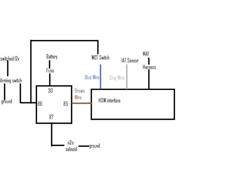
Here’s the Wiring diagram:
Install of a HSW Interface on a LT1, 1994 Camaro, Wide Open Throttle Activation of n2o
If you have any questions or run into problems with the install let me know, I found out pretty much every wrong way to wire it, and talked with Matt at HSW for a long time on how to properly configure it. I know the directions from HSW can be confusing and maybe not laid out in the best order so I have tried to make it as simple as possible. For the purposes of this “how to” we will cover the entire nitrous system wiring to make sure everything is correct. As with any electrical project it is recommended that you remove the cables from the battery and lay the wires out first before cutting and splicing to make sure that everything will go where you want it to. Measure twice, cut once!!!
Needed: 30 amp 4 pin relay, N2O solenoid, WOT switch, Arming switch, wire, crimpers, electrical tape, HSW interface
Here’s the Wiring diagram:
 12-07-2008, 01:48 PM
#2
12 Second Club
Thread Starter
iTrader: (2)
Join Date: Dec 2008
Location: Peoria, AZ
Posts: 371
Likes: 0
Received 0 Likes
on
0 Posts
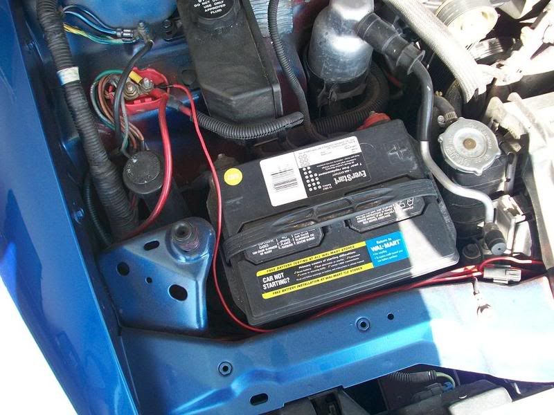
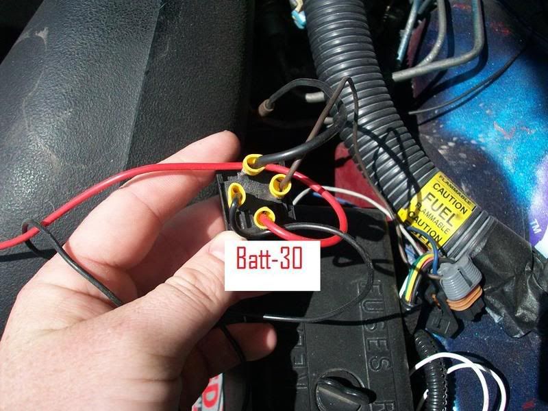
First we will start by running a fused wire from the battery to pin 30 on the relay. (Remove the fuse from the holder until all the wiring is completed to prevent accidental shorting)
Next we will run a wire from pin 87 on the relay to the nitrous solenoid; the other wire from the solenoid will be run to a good ground.
Next a wire is run from a switched (no power when the car is turned off) 12v source to the arming switch. This wire can be run directly to the fuse block, or spliced in with a switched 12v wire.
For my arming switch I used an HSW Camaro Ashtray plate
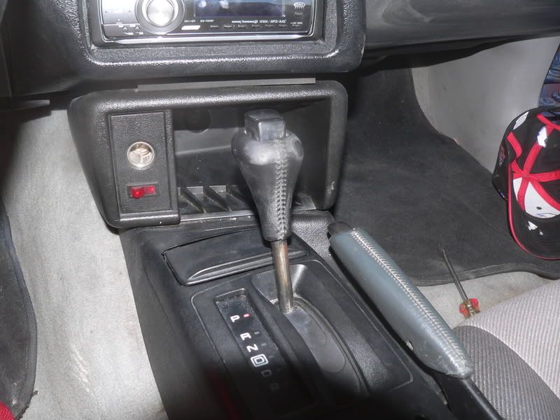
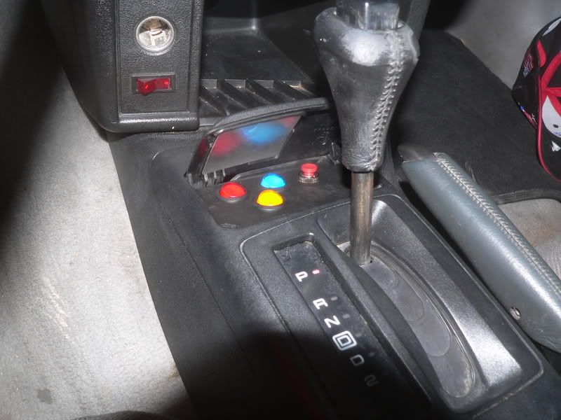
One wire from the arming switch runs to a good ground the other wire from the arming switch runs to pin 86 on the relay.
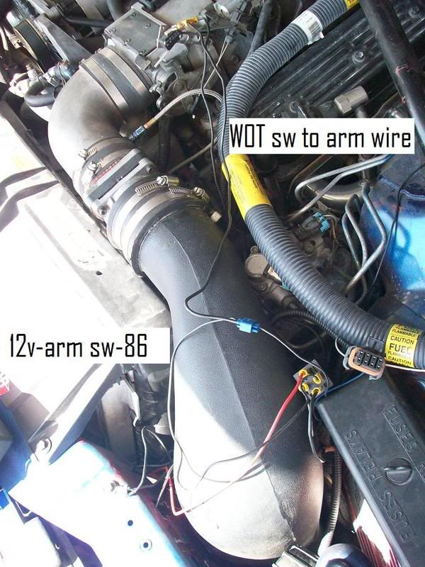
Now it is time to hook up the Wide open throttle switch (WOT sw) since this is how I have decided to activate the nitrous system. A wire will be run from one of the pins on the WOT sw and spliced into the wire that we just ran from the arming switch to the relay. This wire will provide 12v of power to the WOT switch for activation of the n2o system. For this I used a simple inline splicer, but this can be done with soldering or using any type of splicer.
Next we will run a wire from pin 87 on the relay to the nitrous solenoid; the other wire from the solenoid will be run to a good ground.
Next a wire is run from a switched (no power when the car is turned off) 12v source to the arming switch. This wire can be run directly to the fuse block, or spliced in with a switched 12v wire.
For my arming switch I used an HSW Camaro Ashtray plate
One wire from the arming switch runs to a good ground the other wire from the arming switch runs to pin 86 on the relay.
Now it is time to hook up the Wide open throttle switch (WOT sw) since this is how I have decided to activate the nitrous system. A wire will be run from one of the pins on the WOT sw and spliced into the wire that we just ran from the arming switch to the relay. This wire will provide 12v of power to the WOT switch for activation of the n2o system. For this I used a simple inline splicer, but this can be done with soldering or using any type of splicer.
12-07-2008, 01:48 PM
#3
12 Second Club
Thread Starter
iTrader: (2)
Join Date: Dec 2008
Location: Peoria, AZ
Posts: 371
Likes: 0
Received 0 Likes
on
0 Posts
Now we have the basics of the nitrous system set up, we can start installing the HSW interface
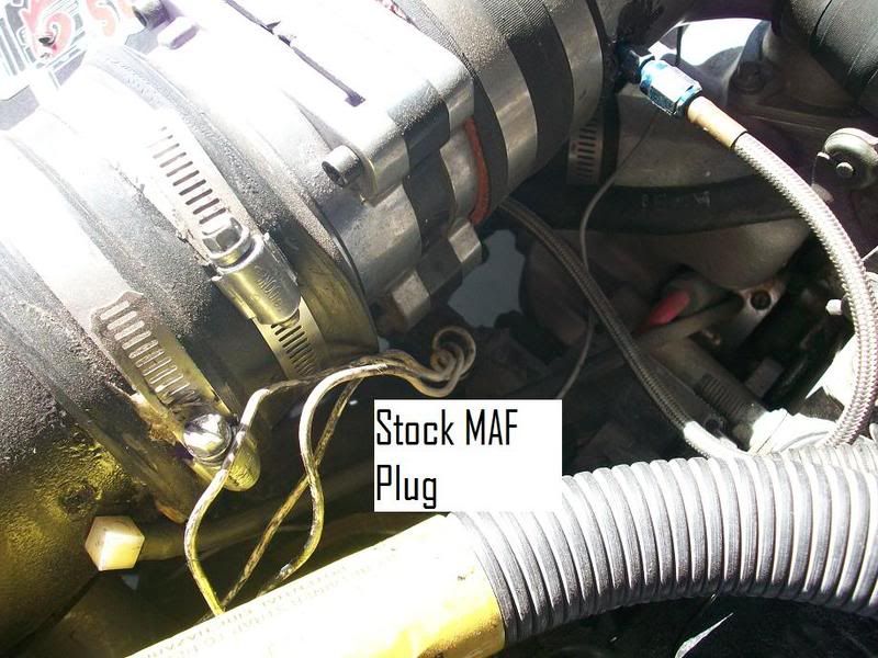
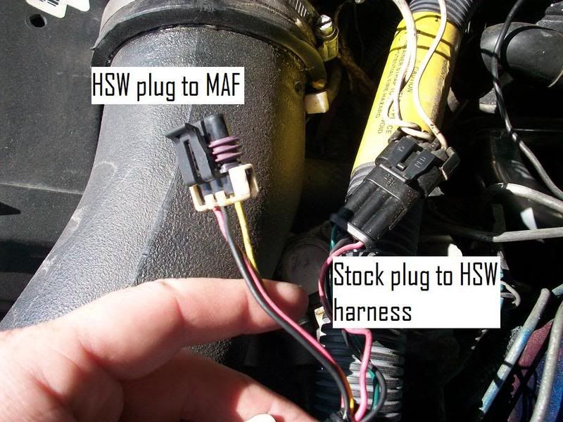
First we need to remove the stock wiring harness from the Mass Airflow Sensor (MAF)
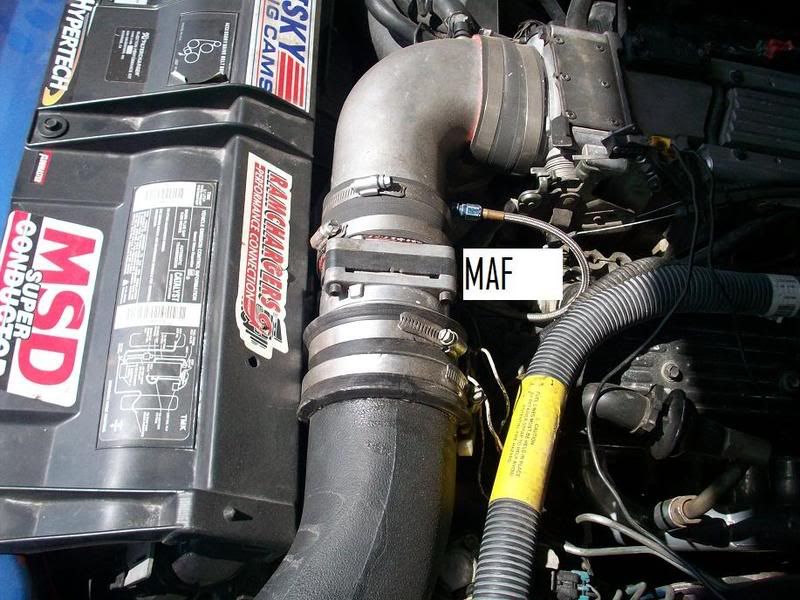
The stock MAF harness can now be plugged into the new HSW MAF harness and the other end of the HSW MAF harness can be plugged into the MAF.
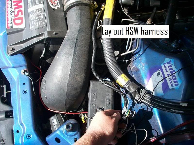
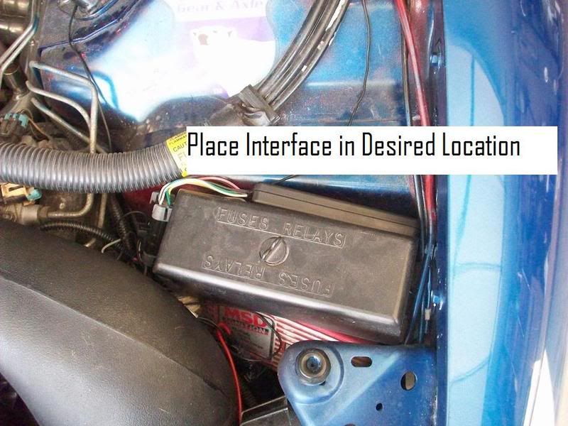
Here again I recommend laying out the HSW MAF harness so you can see how long it is and where you would like to mount the interface, I decided to put the interface behind the engine compartment fuse block.
First we need to remove the stock wiring harness from the Mass Airflow Sensor (MAF)
The stock MAF harness can now be plugged into the new HSW MAF harness and the other end of the HSW MAF harness can be plugged into the MAF.
Here again I recommend laying out the HSW MAF harness so you can see how long it is and where you would like to mount the interface, I decided to put the interface behind the engine compartment fuse block.
12-07-2008, 01:49 PM
#4
12 Second Club
Thread Starter
iTrader: (2)
Join Date: Dec 2008
Location: Peoria, AZ
Posts: 371
Likes: 0
Received 0 Likes
on
0 Posts
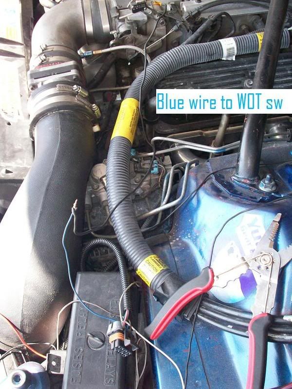
Once we have our location set for the HSW MAF Harness we can begin to wire everything up. We will start with the blue wire. The blue wire is now run to the other pin on the WOT.
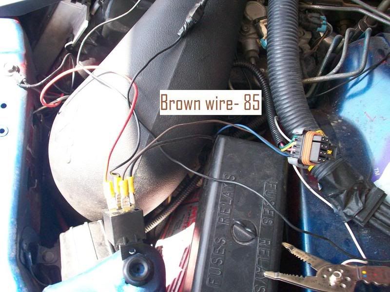
The brown wire is run to pin 85 on the relay
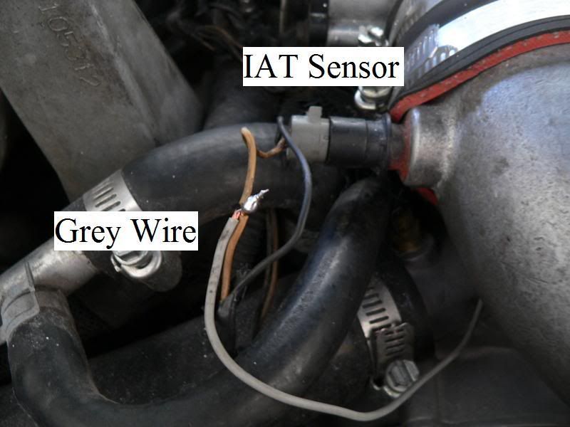
The grey wire is spliced in to the tan wire on the Intake Air Temp sensor (IAT) which is located on the passenger side of the 90 degree elbow going from the MAF to your throttle body. Here you can use an inline splicer or solder it in.
The white wire is optional, it is hooked to pin 13 on the PCM. It is used to control the top end fueling feature (discussed later) if you decide not to wire this up this feature will still work but it will rely on the MAF rather than rpm. I did not hook this up
The brown wire is run to pin 85 on the relay
The grey wire is spliced in to the tan wire on the Intake Air Temp sensor (IAT) which is located on the passenger side of the 90 degree elbow going from the MAF to your throttle body. Here you can use an inline splicer or solder it in.
The white wire is optional, it is hooked to pin 13 on the PCM. It is used to control the top end fueling feature (discussed later) if you decide not to wire this up this feature will still work but it will rely on the MAF rather than rpm. I did not hook this up
12-07-2008, 01:49 PM
#5
12 Second Club
Thread Starter
iTrader: (2)
Join Date: Dec 2008
Location: Peoria, AZ
Posts: 371
Likes: 0
Received 0 Likes
on
0 Posts
Configuring the Interface
Here’s is where the directions from HSW get very confusing, it is actually fairly simple and I will go in order section by section starting with the upper left section:
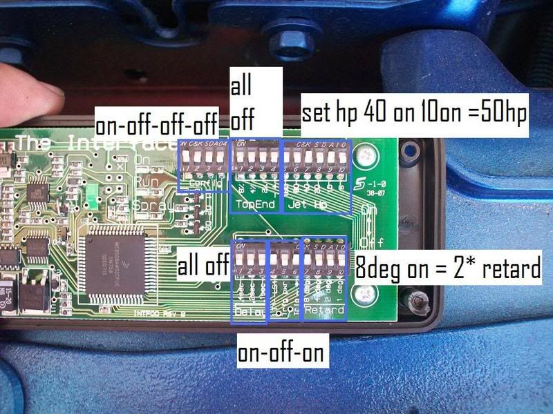
The first section is the configuration section, since we are using an LT1 we need to have these 4 switches set to On Off Off Off. Simple enough
The next section is the Top end fueling section, most people will not need to use this section and it can be left off. If you have a wide band o2 sensor and you notice that at high RPM’s your air/fuel ratio is going lean or rich you can use this section to correct the problems. If you need to add fuel because your mixture is going to lean, turn the +/- switch on and use the dip switches to control how much fuel you would like to add or subtract. For example if you only need to add 2%, turn the 2% switch on, if you need to add 10% turn the 2% and the 8% switches on 2+8=10. If you need to subtract fuel because your top end mixture is running to rich leave the +/- switch turned off and use the dip switches the same way as if you were adding fuel.
The next section is the Jet HP section. For the purposes of this install we have used a 50hp jet. This section works the same way as the top end section, for a 50hp shot turn on the 40 and 10 switches, for a 100 shot turn on the 80 and 20 switches.
The next section (bottom row left) is the delay section, this section you will probably not need and can be left turned off. This section will delay adding fuel if you notice on your wideband o2 sensor that you are having a rich spike in your mixture. This section works the same as the previous two, add up the milliseconds below the switches to get the correct total time you would like to delay the adding of fuel.
The next section tells the interface how we are activating the nitrous system. The first switch must be turned on, even though it says lt1-ls1 turn it on. Since we are using 12 volts from the arming switch to the WOT switch to activate our nitrous system we need to have the trigger power switch turned off and the +/- switch turned on.
The last section is the timing retard section. The directions from HSW can be confusing here and do not give you all the information. Ignore the deg mark next to the numbers under the dip switches, that is not how much timing you are going to pull. This feature tricks your IAT and pcm into pulling the timing for you. Here is a chart I made that shows which switch you need to turn on to pull how much timing on a stock pcm.
Timing pull required---------switch total to turn on
1deg 6
2deg 8
3deg 13
6deg 14
8deg 15
If you need to pull other than 1,2,3,6, or 8 degrees of timing you must use a program like tuner cat to go in and adjust your pcm. I can help you do this if needed
Here’s is where the directions from HSW get very confusing, it is actually fairly simple and I will go in order section by section starting with the upper left section:
The first section is the configuration section, since we are using an LT1 we need to have these 4 switches set to On Off Off Off. Simple enough
The next section is the Top end fueling section, most people will not need to use this section and it can be left off. If you have a wide band o2 sensor and you notice that at high RPM’s your air/fuel ratio is going lean or rich you can use this section to correct the problems. If you need to add fuel because your mixture is going to lean, turn the +/- switch on and use the dip switches to control how much fuel you would like to add or subtract. For example if you only need to add 2%, turn the 2% switch on, if you need to add 10% turn the 2% and the 8% switches on 2+8=10. If you need to subtract fuel because your top end mixture is running to rich leave the +/- switch turned off and use the dip switches the same way as if you were adding fuel.
The next section is the Jet HP section. For the purposes of this install we have used a 50hp jet. This section works the same way as the top end section, for a 50hp shot turn on the 40 and 10 switches, for a 100 shot turn on the 80 and 20 switches.
The next section (bottom row left) is the delay section, this section you will probably not need and can be left turned off. This section will delay adding fuel if you notice on your wideband o2 sensor that you are having a rich spike in your mixture. This section works the same as the previous two, add up the milliseconds below the switches to get the correct total time you would like to delay the adding of fuel.
The next section tells the interface how we are activating the nitrous system. The first switch must be turned on, even though it says lt1-ls1 turn it on. Since we are using 12 volts from the arming switch to the WOT switch to activate our nitrous system we need to have the trigger power switch turned off and the +/- switch turned on.
The last section is the timing retard section. The directions from HSW can be confusing here and do not give you all the information. Ignore the deg mark next to the numbers under the dip switches, that is not how much timing you are going to pull. This feature tricks your IAT and pcm into pulling the timing for you. Here is a chart I made that shows which switch you need to turn on to pull how much timing on a stock pcm.
Timing pull required---------switch total to turn on
1deg 6
2deg 8
3deg 13
6deg 14
8deg 15
If you need to pull other than 1,2,3,6, or 8 degrees of timing you must use a program like tuner cat to go in and adjust your pcm. I can help you do this if needed
12-07-2008, 01:50 PM
#6
12 Second Club
Thread Starter
iTrader: (2)
Join Date: Dec 2008
Location: Peoria, AZ
Posts: 371
Likes: 0
Received 0 Likes
on
0 Posts
Now we can plug the interface into the harness, put the fuse back in the wire from the battery to pin 30 on the relay and test the system. I suggest unhooking you bottle for initial testing. First turn the key to on not run, do not start the engine, the on light may be blinking on the interface that is okay. Arm your system, again ensuring that the bottle is unhooked. With the system armed push the WOT sw and listen for the solenoid to click and the spray light on the interface to come on. If you would like to test the n2o system make sure your rpm's are above about 3000 rpm before activating the n2o system.
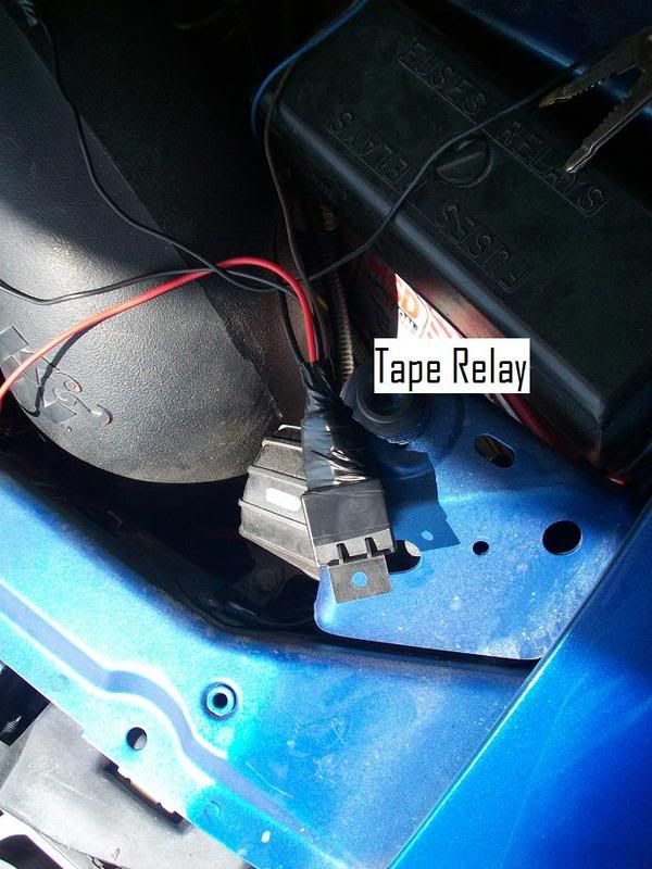
Now that we have tested everything I suggest wrapping the relay in electrical tape to prevent any wires coming lose or shorting against the body of the car
And finally close up the interface and stow it, and hide all the wires as you so choose.
Again if you have any questions please let me know and I will help as much as possible.
Doug “BEEF” T.


