

FPSS and FJO wiring question
 05-09-2006, 06:06 PM
#1

OK... well first and foremost... can i just put the FPSS right on the fuel rail and run the fuel line from it to the solenoid?
And then, what ground do I run through the FPSS? There are two grounds off the controller or do i run off the OTHER ground on the relay that does not go to the FJO?
And then, what ground do I run through the FPSS? There are two grounds off the controller or do i run off the OTHER ground on the relay that does not go to the FJO?

 05-09-2006, 08:07 PM
#3
Originally Posted by cleveland
you are correct about the inline fpss near the fuel rail, also, run the negative off the relay to the fpss and then to a good ground.
-Dan
-Dan
so the ground that does not go tothe FJO controller correct? i'll post pics of how im going to wire it in a bit...

Trending Topics
 05-11-2006, 04:07 PM
#12
Closed ex-Sponsor Account
iTrader: (1)

Join Date: Jul 2004
Location: Wichita Falls, TX
Posts: 2,797
Likes: 0
Received 0 Likes
on
0 Posts
Originally Posted by Dragframe
ok... wow... hard to follow... but looking like its similar to what i thought of last night. I show what i was thinking (probly same thing just easier layout) and see if you agree...
thanks for all your help and time!!
thanks for all your help and time!!
Good luck
Ricky
05-11-2006, 05:39 PM
#13

Could you Put the FPSS is series with the arming input of the FJO? This would probably be easier for me. are there any draw back's of connecting it that way?
Last edited by Oatmeal; 05-11-2006 at 10:47 PM.
05-11-2006, 06:21 PM
#14
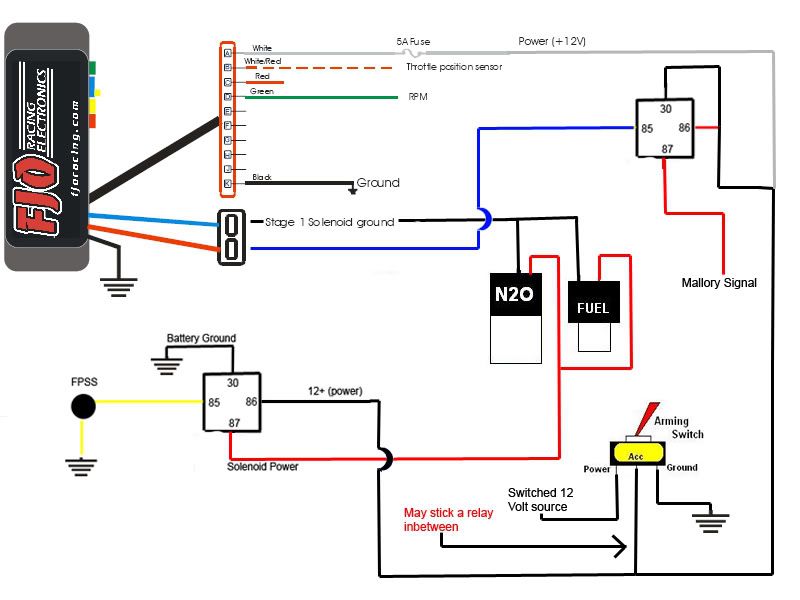
take a look at this... I would jsut set the stage two to a 100% while the stage one is firing the solenoids... wold work correct? and simple...
I see in your diagram you have the relays pulling power from the switch that arms the FJO... now isn't that too much current for a little switch and won't it burn it up?

I see in your diagram you have the relays pulling power from the switch that arms the FJO... now isn't that too much current for a little switch and won't it burn it up?
Last edited by Dragframe; 05-11-2006 at 06:33 PM.
05-11-2006, 07:13 PM
#15
Closed ex-Sponsor Account
iTrader: (1)
Join Date: Jul 2004
Location: Wichita Falls, TX
Posts: 2,797
Likes: 0
Received 0 Likes
on
0 Posts
Not to much current at all relays pull under 1 amp each and the controllers arming switch only pulls mili amps so its good. You drawing on terminal 30 will send a ground signal to your mallory box. I thought you said you needed a hot signal.???
Ricky
Ricky
05-11-2006, 07:46 PM
#16
Originally Posted by NXRICKY
Not to much current at all relays pull under 1 amp each and the controllers arming switch only pulls mili amps so its good. You drawing on terminal 30 will send a ground signal to your mallory box. I thought you said you needed a hot signal.???
Ricky
Ricky
oh yeah crap... so... how should i arange that relay for the mallory box so when the FJO grounds it will give the Mallory box power? My understanding of what terminal on the relay does what sucks. lol. I figured this would hold off power untill it was grounded...
and the rest works correct?
if you could jsut switch the numbers around in my lil replay in my pic and explain why it has to be that way it would be awesome!
Thanks for yor help.... this is a helluva learning experience... after we get hte replays figured out... imma double check the arrangment that i choose for switches with you then i should be ready to rock...
Last edited by Dragframe; 05-11-2006 at 08:00 PM.
05-11-2006, 10:45 PM
#17
Closed ex-Sponsor Account
iTrader: (1)
Join Date: Jul 2004
Location: Wichita Falls, TX
Posts: 2,797
Likes: 0
Received 0 Likes
on
0 Posts
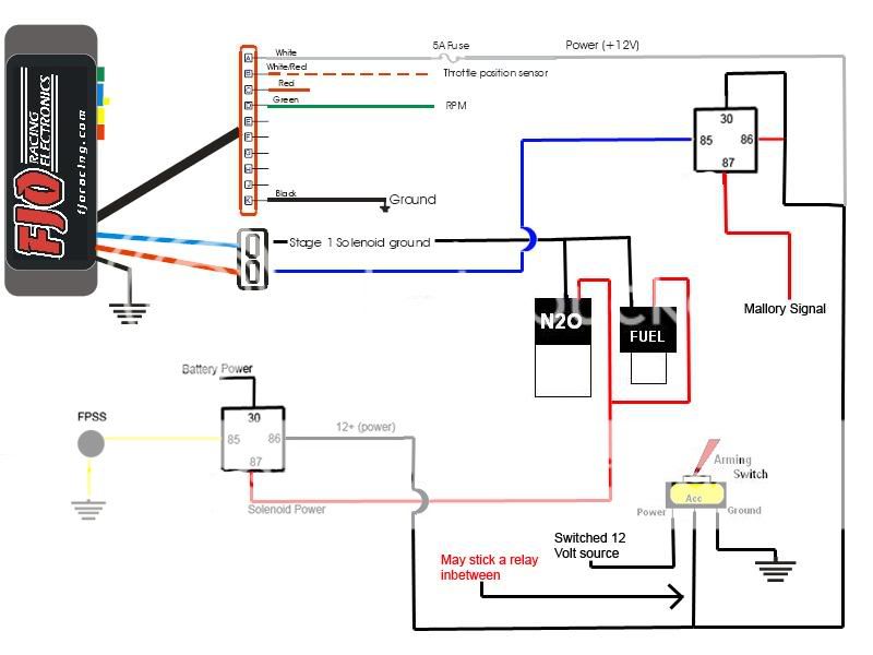
Take your 30 & 86 and just put those together as in my pic toggle switch send power to the coil terminal 86 and the common terminal 30. When the FJO grounds the coil terminal 85, then the relay clicks, 30 and 87 are put together and you have 12 volts on 87. loose ground or hot relay opens and terminal 87 goes dead.
hope this helps.
Ricky
hope this helps.
Ricky
 05-12-2006, 09:03 AM
#19
Closed ex-Sponsor Account
iTrader: (1)
Join Date: Jul 2004
Location: Wichita Falls, TX
Posts: 2,797
Likes: 0
Received 0 Likes
on
0 Posts
NOPE, now you have got all the noids amp draw going thro the arming switch. That switch is just for low amp control.
Do you not like the drawing I gave to you, it will work the way you need it to...
Do you not like the drawing I gave to you, it will work the way you need it to...
05-12-2006, 12:21 PM
#20
Originally Posted by NXRICKY
NOPE, now you have got all the noids amp draw going thro the arming switch. That switch is just for low amp control.
Do you not like the drawing I gave to you, it will work the way you need it to...
Do you not like the drawing I gave to you, it will work the way you need it to...
I guess a write up on relays would be a good amount of help.
As for my drawing... im not sure how it is much different than yours... Numbers look to be about the same on the relays and all... I guess my minimal understanding of relays is why! lol..
EDIT: ok... so if I make the 30 on the solenoid relay go to power instead of ground, I will be set? Like so...
Last edited by Dragframe; 05-12-2006 at 04:36 PM.