12v key on
 03-02-2011, 09:58 AM
#1
On The Tree
Thread Starter
iTrader: (2)
Join Date: Jul 2008
Location: bay area
Posts: 135
Likes: 0
Received 0 Likes
on
0 Posts

so im looking for the best wire to tap into so i can power a few things .. line lock, shift light, wide band A/F.. trying to make it a very clean wire setup so im not trying to tap into a bunch of diff wires. are all the 12v key on wires all the same gauge? was thinking i could run the 12v key on to a relay, then run a wire straight from the battery to the relay to power my key on stuff.. any ideas? thnaks
 03-02-2011, 10:05 AM
#2
This was covered a few posts down from here:
https://ls1tech.com/forums/stereo-el...ce-gauges.html
Driver's side fuse panel (interior):
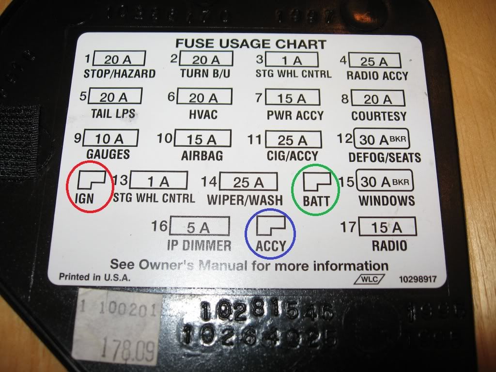
Red Circle = IGN = Switched 12V Power (has power when key is in the on position, but does not have power otherwise)
Green Circle = BATT = 12V Always Hot (has power regardless of key position)
Blue Circle = ACCY = 12V Retained Accessory Power (best example is the radio - this will energize when the car is turned on, and will stay powered even after the car is turned off, but will turn off once the door is opened)
These slots can be accessed by using a flat blade connector crimped on the end of a wire (then use the wire to power whatever you wish) - just shove the connector in the appropriate slot from the front of the panel.
https://ls1tech.com/forums/stereo-el...ce-gauges.html
Driver's side fuse panel (interior):
Red Circle = IGN = Switched 12V Power (has power when key is in the on position, but does not have power otherwise)
Green Circle = BATT = 12V Always Hot (has power regardless of key position)
Blue Circle = ACCY = 12V Retained Accessory Power (best example is the radio - this will energize when the car is turned on, and will stay powered even after the car is turned off, but will turn off once the door is opened)
These slots can be accessed by using a flat blade connector crimped on the end of a wire (then use the wire to power whatever you wish) - just shove the connector in the appropriate slot from the front of the panel.
 03-06-2011, 08:22 PM
#5
How can you tell the circuits are 15amp each?? I'm lost where your seeing this. I'm also trying to hook up my gauges, Meents has helped me so far. He has told me about the flat connectors I need and also the inline fuses. Since the only gauge I am hooking up has to have the keyed 12v source, which one should I hook it up to?? Its my trans temp gauge.
03-06-2011, 09:05 PM
#6
Keyed 12V source = IGN on the fuse panel shown above
The reason they are asking you to hook it up that way is so that the gauge only has power when the key is in the ON position - if you hooked it up to a 12V source that was hot all the time (like straight to the battery), the gauge would always be drawing power, and it would eventually run your battery down.
Those three slots on the driver's side fuse panel were specifically put there by GM to wire in aftermarket accessories.
Trending Topics
03-07-2011, 06:51 AM
#8
Without drawing a diagram, it would kinda look like:
Blade connector - 12 gauge wire - wire tap w/ wire for new accessory - fuse - accessory
So each new branch would get a wire tap, a fuse, and a wire run to the new accessory. I'm currently running around 4-5 different things off that one wire by doing that.
03-07-2011, 07:23 AM
#9
I connected a wire to the port then put the bare end to my tongue and touched a good ground to get an estimate of current flow. 
Seriously, I looked it up on the factory wiring schematics a few years ago.
I ran wires from each of the three add-on ports in the fuse box to small accessory fuse panels mounted under the dash behind the radio/HVAC controls. That way, when I need to add a new accessory, I already have whatever type of power I need in a readily accessible location.
03-07-2011, 03:50 PM
#11
9 Second Club
iTrader: (10)
Join Date: Apr 2009
Location: Joliet,IL and Las Vegas 50/50
Posts: 1,230
Likes: 0
Received 3 Likes
on
3 Posts
^I think mine is there last time I looked.
If you are running three gauges could you run all the gauges off of one fuse to eliminate multiple fuses. I don't think those gauges pull much more than an amp each. The only downside I see is if the fuse blows then you all three go down until the fuse is replaced.
If you are running three gauges could you run all the gauges off of one fuse to eliminate multiple fuses. I don't think those gauges pull much more than an amp each. The only downside I see is if the fuse blows then you all three go down until the fuse is replaced.
03-07-2011, 06:23 PM
#12
The one you want is the red circle out of the 3 shown. As for running more than one wire, you shouldn't have to. What you can do is run a larger gauge wire (like 12 or 14 gauge) from that slot, and then just run it under the dash for easy access. Any time you want to run a new accessory, just install a wire tap along that existing line so that you can make a branch off of the first line you ran.
Without drawing a diagram, it would kinda look like:
Blade connector - 12 gauge wire - wire tap w/ wire for new accessory - fuse - accessory
So each new branch would get a wire tap, a fuse, and a wire run to the new accessory. I'm currently running around 4-5 different things off that one wire by doing that.
So, see if this sounds ok.. I already have some 16 gauge wire from a boat project. My 2 gauges are in the place of the vents above the head unit (pretty nice piece from 6LE). Go ahead and run the wire from the fuse box up to the 2 gauges. Splice both gauges 12v wire into the 16 gauge wire from the fuse box. Inbetween the gauges and the splice, add a inline fuse? Or could I put the fuse on the 16 gauge?
And another question, the trans temp gauge has a 12v light. If I just ran the light to the ignition, that just means it would be on all the time. Would that be a problem other than probably burning the bulb out quicker??
Sorry guys for all the trouble.. I just really don't understand wiring. I'm slowly getting what you are saying though.
03-07-2011, 06:45 PM
#13
I wanted my gauge lights to come on when the rest of the gauges were on (that is when the headlights are turned on) - in order to do that, you'll want to install a tap on the GREEN wire on the back of the dimmer switch (next to the headlight switch) and run that wire to the wire on the gauge for the light.
As for the fuse question, I'd probably just fuse the wire straight off the slot if all you are powering is the gauges. Although it will be a single point of failure, it is also one less thing to worry about wiring since you'll have one instead of two fuses.
As for the fuse question, I'd probably just fuse the wire straight off the slot if all you are powering is the gauges. Although it will be a single point of failure, it is also one less thing to worry about wiring since you'll have one instead of two fuses.
03-07-2011, 07:33 PM
#14
I wanted my gauge lights to come on when the rest of the gauges were on (that is when the headlights are turned on) - in order to do that, you'll want to install a tap on the GREEN wire on the back of the dimmer switch (next to the headlight switch) and run that wire to the wire on the gauge for the light.
As for the fuse question, I'd probably just fuse the wire straight off the slot if all you are powering is the gauges. Although it will be a single point of failure, it is also one less thing to worry about wiring since you'll have one instead of two fuses.
As for the fuse question, I'd probably just fuse the wire straight off the slot if all you are powering is the gauges. Although it will be a single point of failure, it is also one less thing to worry about wiring since you'll have one instead of two fuses.
Thanks so much for the help meents. You have pretty much walked me through this process step by step.
I'm assuming by your signature and username, are you the Tom Meents that drives the monster truck??
 03-09-2011, 07:04 PM
#16
Meents, I'm installing the gauges tomorrow since I'm off and have been trying to think this through the best I can. I have two more questions for ya real quick.
First, when tapping into the GREEN wire behind the dimmer switch, how exactly does this need to be done? What I'm asking is, when I cut the GREEN wire, it will be in 2 pieces. So, how exactly do I need to tie my 12v lighting wire from the gauge into this. I didn't think a regular wire tap would work if its what I'm thinking it is.
Second, when I run my 14 gauge wire from my fuse box, I'll have the inline fuse somewhere between it and where I tie it into my 2 gauges 12v key on wire. How do I need to tie both the 12v wires into the single 14 gauge wire??
Thanks so much..
03-09-2011, 09:46 PM
#18
When you use a wire tap (at least the ones I'm thinking of), what they do is go around the existing wire, and you put the additional wire right next to it, as shown in the picture below:
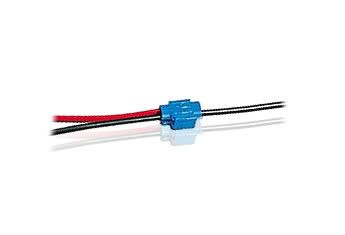
With those wires in place, you'll take a pair of pliers and clamp down on the metal tang that sticks out of it, driving it into both wires. That tang looks like it would cut the wire, but if you look closely, it is shaped in such a way that it will pierce through the wire insulation, but won't actually cut the conductor - it will contact the conductor in each wire, and that's what makes the electrical connection.
If you want to keep it simple, you could do something similar with the wire you are running off of the fuse panel...put a fuse in line, and then use two separate wire taps on that wire to run one wire to each gauge. You could also run one wire into one end of a crimp-on, butt style connector, and two wires to the other side, crimp everything and call it a day.
What you'll want to make sure you have a handle on is the appropriate wire gauge for the wire taps you will be using - typically, one size of wire tap will be for 10-12 gauge wire (so all wires will have to be that size), another will handle 14-16 gauge, and the smallest will handle 18-22. What you will probably want to do is just use 14 gauge off of the fuse panel, and 14 or 16 gauge wire to each of the gauges. They really won't draw much power at all, so wire size isn't a huge concern here.
03-09-2011, 09:49 PM
#19
Oh...and as for the switched 12V power, there is one available at the ASR switch - on my 2002, it is the pink wire. You'd have to verify that the brown wire is the correct wire for 98s, but that could be as simple as just installing a wire tap on that wire and seeing if everything works like it should. If it doesn't, just remove the wire tap, tape over the insulation where the tang pierced the wire, and try again.
