


LS1 Rear Mid-Engine AWD (C5 Corvette donor)

Thread Starter
Registered User
Joined: May 2013
Posts: 22
Likes: 0
You could be right tonypaul. It can be a little confusing. I'll try to mock something up in Photoshop later to clarify.
In the meantime, let's see...
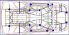
The rear diff will be under but in front of the engine (if you are facing the belts/pulleys - looking toward the rear of the car). I believe the front of the engine (where the belts are) will basically be sitting on top of the rear diff. As mentioned before, the LS1 will have a dry sump so it will be able to sit lower and (hopefully) allow enough clearance for the rear drive shaft. I know there are a couple of big assumptions in there. Of course it is difficult to tell exactly how it will all line up until I have the parts. It would be nice to get exact dimensions of the engine/tranny to try to mock this up but I don't know where to get that info. Anyone else know?
Anyway, the engine and transmission are both mounted together normally but flipped around backwards which puts the output shaft of the transmission turning the normal direction but pointing toward the front of the vehicle instead of the rear. This effectively has the shaft turning in the wrong direction. The shaft is connected to the V-Dirve which directs the power back toward the rear of the vehicle which fixes the reverse rotation problem. The t-case is mounted to the other shaft of the V-Drive which is pointing toward the rear of the vehicle. This puts the t-case in the correct orientation with the rear shaft running straight through the t-case and the front shaft pointing toward the front of the vehicle. Both of these are now running in the correct rotation due to the V-Drive and the power split is corrected returning to a rear-biased 35/65 front/rear split. So, we run the rear driveshaft from the t-case to the rear diff. We shouldn't have to do anything with this diff because the driveshaft is now turning in the correct direction. We run the front driveshaft to the reverse rotation diff in the front. We need a reverse rotation diff here because it is in the front and we don't want the gears running on the coast side.
Have I overlooked anything?
Mike
In the meantime, let's see...
The rear diff will be under but in front of the engine (if you are facing the belts/pulleys - looking toward the rear of the car). I believe the front of the engine (where the belts are) will basically be sitting on top of the rear diff. As mentioned before, the LS1 will have a dry sump so it will be able to sit lower and (hopefully) allow enough clearance for the rear drive shaft. I know there are a couple of big assumptions in there. Of course it is difficult to tell exactly how it will all line up until I have the parts. It would be nice to get exact dimensions of the engine/tranny to try to mock this up but I don't know where to get that info. Anyone else know?
Anyway, the engine and transmission are both mounted together normally but flipped around backwards which puts the output shaft of the transmission turning the normal direction but pointing toward the front of the vehicle instead of the rear. This effectively has the shaft turning in the wrong direction. The shaft is connected to the V-Dirve which directs the power back toward the rear of the vehicle which fixes the reverse rotation problem. The t-case is mounted to the other shaft of the V-Drive which is pointing toward the rear of the vehicle. This puts the t-case in the correct orientation with the rear shaft running straight through the t-case and the front shaft pointing toward the front of the vehicle. Both of these are now running in the correct rotation due to the V-Drive and the power split is corrected returning to a rear-biased 35/65 front/rear split. So, we run the rear driveshaft from the t-case to the rear diff. We shouldn't have to do anything with this diff because the driveshaft is now turning in the correct direction. We run the front driveshaft to the reverse rotation diff in the front. We need a reverse rotation diff here because it is in the front and we don't want the gears running on the coast side.
Have I overlooked anything?
Mike
You could be right tonypaul. It can be a little confusing. I'll try to mock something up in Photoshop later to clarify.
In the meantime, let's see...
The rear diff will be under but in front of the engine (if you are facing the belts/pulleys - looking toward the rear of the car). I believe the front of the engine (where the belts are) will basically be sitting on top of the rear diff. As mentioned before, the LS1 will have a dry sump so it will be able to sit lower and (hopefully) allow enough clearance for the rear drive shaft. I know there are a couple of big assumptions in there. Of course it is difficult to tell exactly how it will all line up until I have the parts. It would be nice to get exact dimensions of the engine/tranny to try to mock this up but I don't know where to get that info. Anyone else know?
Anyway, the engine and transmission are both mounted together normally but flipped around backwards which puts the output shaft of the transmission turning the normal direction but pointing toward the front of the vehicle instead of the rear. This effectively has the shaft turning in the wrong direction. The shaft is connected to the V-Dirve which directs the power back toward the rear of the vehicle which fixes the reverse rotation problem. The t-case is mounted to the other shaft of the V-Drive which is pointing toward the rear of the vehicle. This puts the t-case in the correct orientation with the rear shaft running straight through the t-case and the front shaft pointing toward the front of the vehicle. Both of these are now running in the correct rotation due to the V-Drive and the power split is corrected returning to a rear-biased 35/65 front/rear split. So, we run the rear driveshaft from the t-case to the rear diff. We shouldn't have to do anything with this diff because the driveshaft is now turning in the correct direction. We run the front driveshaft to the reverse rotation diff in the front. We need a reverse rotation diff here because it is in the front and we don't want the gears running on the coast side.
Have I overlooked anything?
Mike
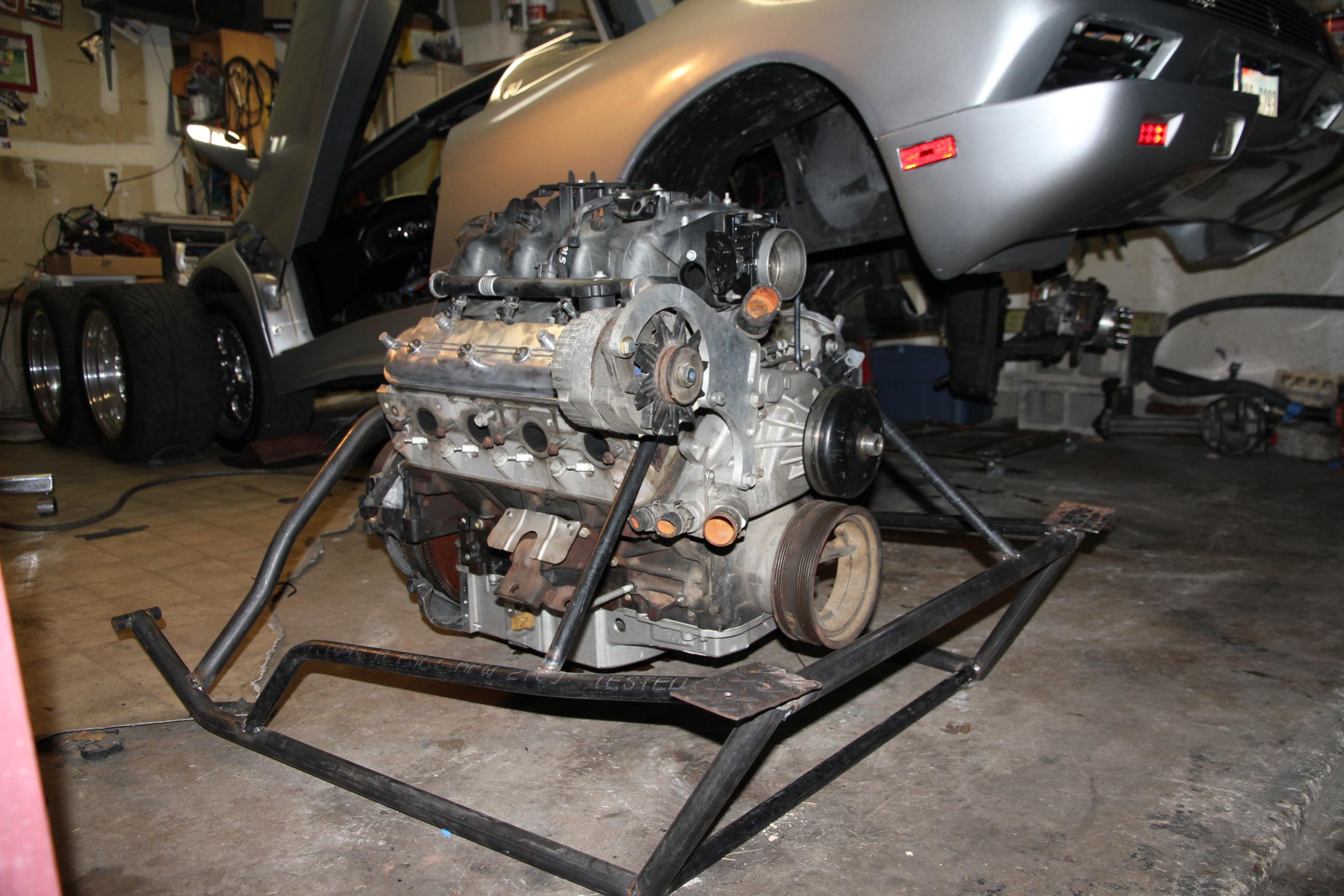
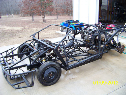
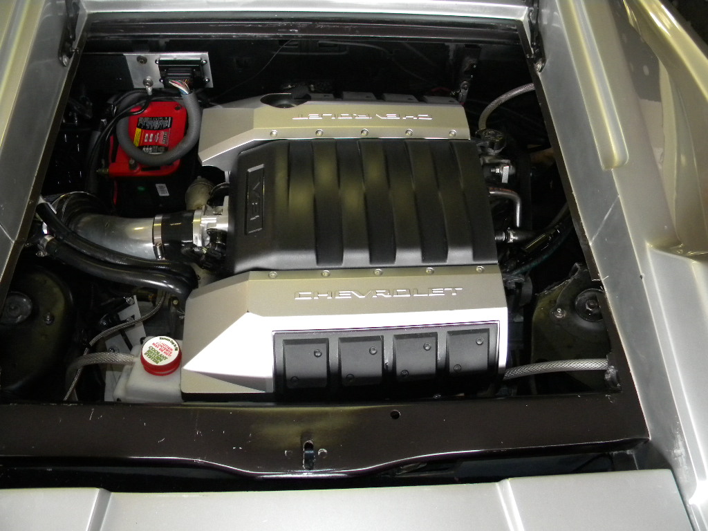
Here is a pic of when I was trying to mock up the reverse rotated ls3. You can see where I had to place the diff right between the front of the oil pan and the balancer. And that was about 1" behind (towards the rear of the car) the axle centerline. I figured I could make make up the 1" to far back with the c/v axles:
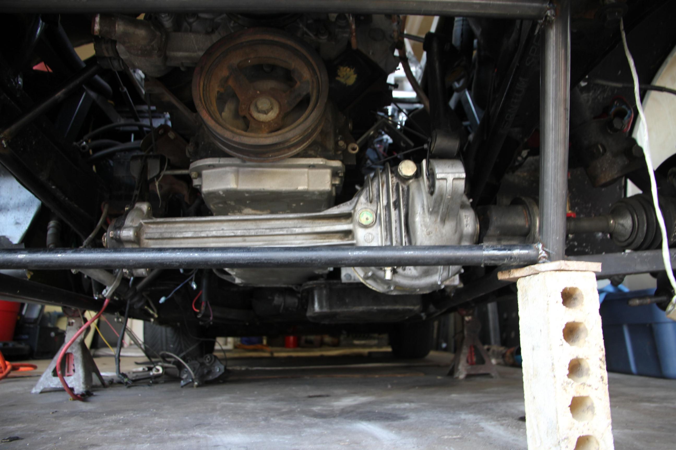
Here a couple other pics to give you a idea of what I was trying to do:
I just think your not going to have all the room you need mainly in the rear diff area and under the car for a drive shaft coming off a Vdrive. Also have found a Vdrive that fit/work? Some are a chain drive that doesnt change the rotation and some a gear driven that change the rotation. The ones I have been around in jet/racing boats are noisy as hell....
Over all its a cool concept and I could see it happening on sand rail or something but in a kit car I cant see it fitting. I hope you can figure it out~
For some reason the pics I wanted to load are not loading....
But are are a few to give you some ideas:
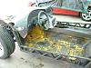
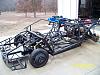
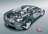
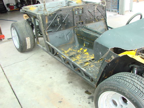
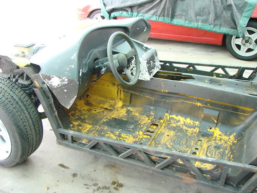
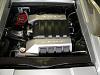
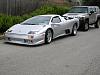
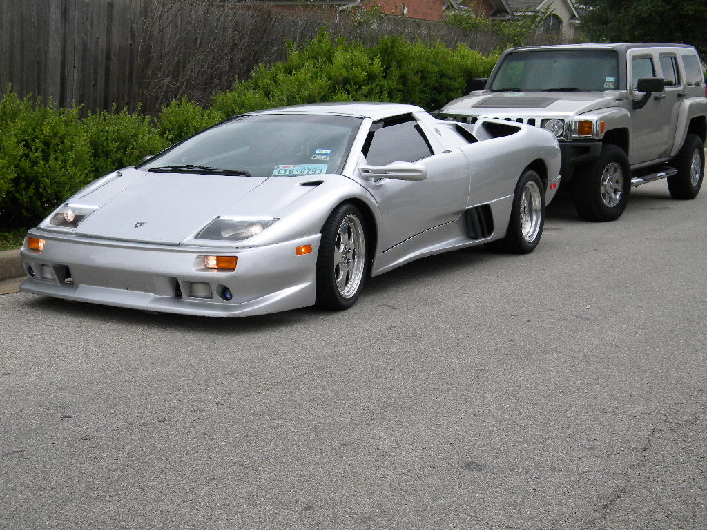
First 2 are of my Diablo, even though its on a streched Fiero chassis it might give you some idea of how little space there is to work with. The others are just for inspiration~~

But are are a few to give you some ideas:
First 2 are of my Diablo, even though its on a streched Fiero chassis it might give you some idea of how little space there is to work with. The others are just for inspiration~~

Thread Starter
Registered User
Joined: May 2013
Posts: 22
Likes: 0
I do have a set of Naerc plans but I haven't decided if I am going to go that route yet.
I am fairly flexible about engine placement. The description I gave you was just an off-the-cuff. Is there a reason the rear diff has to be in front of the harmonic balancer? rather stretch the frame than make the passenger cabin smaller but I'd rather not do either. Are you saying the LS1 is larger than the V12 in the Murcielago and that is why it won't fit? That seems hard for me to believe. Can't I just keep moving the engine toward the back of the car until it fits? This really has nothing to do with AWD by the way. This problem has to be solved no matter what. Other people have used the LS1 in a lambo kit haven't they? I can't be the first...I guess I'll have to go dig up some examples.
Yes, I have found two gear-based V-Drives that are used in racing applications that we think will work. One was the casalev pictured in this thread. I hope they aren't THAT noisy. I hadn't thought of that. That would be a bummer.
Thanks. I hope I can make it work but even if I can't, I will build something cool. I am just hoping to build something REALLY cool.
Mike

Registered User
Joined: Apr 2013
Posts: 1
Likes: 0
While I applaud your motivation but I just cant begin to tell you how big of project this is going to be. Im not here to bash you or tell you its a bad idea, its just a way bigger of project than you can imagine.
...First - just completing ... is almost impossible for someone who doesnt personally have a strong skill set in welding and fiberglass/paint work and a large investment of tools and a good working space. ........will have to depend alot on someone else's skills and schedule (i.e. free time) to help you with your project will greatly slow down your build. ...
...Second- The money.... In your head right now it seems very doable, a little money here a little money there and its done.... ...The way these things work is something always comes up in these builds, lose a job, family issues, health, wives, girlfriends, (sometimes both) ect, ect. ......
.....unmotivate alot of people and they end up selling the whole unfinished project for $4000.00 on craigslist....
...
In closing, Im not trying to bash you in anyway, maybe just prepping you for whats ahead. My advice- Find someone elses' unfinished replica project and keep it simple.
I'm just going to jump in here, because my heart sank when I just read BigPines project. And then I read Tony's comments, which truly encapsulated all the negative emotions that I was feeling.
I myself have profited from TWO cars that were someone else's similar projects. In both cases, they were begun by someone with greatest of ambition and enthusiasm; both died on the vine after about 3 years of work, and 3-5 years of sitting and "waiting." They already had $80,000 and $65,000 invested in them, and I bought one for $12,000 and the other for $7500.
TP is absolutely correct -- UNPREDICTED life circumstances come up, and that is a guarantee. Furthermore, when you rely on someone else, you immediately have set yourself up for failure, because they, too, will have life circumstances, PLUS they have their own lives to lead. They will drop out of the project because they must -- not because they want to.
Like TP says, I'm not here to bash your ideas and dreams, but my heart truly sinks because I know the outcome.
I come from the Porsche forum, where I have witnessed over the past 3 years at least a dozen turbo projects that started similarly, but then fizzled -- and these were just the ones that guys posted; there were probably a couple dozen others that similarly fizzled.
Adding a turbo to a Porsche is EASY in comparison; in fact, it truly can be done in 3-5 days! But STILL, these dozen projects failed to sustain -- and in fact, I bought someone's whole turbo kit, already sorted out and tailor made to just bolt on, from one of the failure projects. Very cheaply, too. The biggest factors? Time, money, "social circumstances ("...job, girlfriends, marriage, kids, etc...."), and unforeseen mechanical complications during the build.
SUGGESTION: Look around for someone's abandoned project (yes, check Craigslist around the nation); buy it cheap! Really really bargain it down, and WAIT a few months if they won't budge, because they WILL budge. Typically, the wife starts pressuring to get it out of the yard or to make space in the garage, or worse yet, if you have it tying up someone else's garage.
Even more typically, the owner gets tired of the project, loses interest, or finds another BETTER car that is running. In fact, that one car that I got that already had $80K in it (with receipts) which I got for $12K? -- I could have got it for less, if I had just really lowballed them. But, there was no one to give me advice about this subject.
Do not be ashamed of lowballing! I already have another $10K in that $80K car, and it STILL is going to need about another $3-5K or so! BUT, it is driving and on the road.
Don't be another statistic because you think you are "not like those hundreds ahead of you!"
Thread Starter
Registered User
Joined: May 2013
Posts: 22
Likes: 0
Thanks stasha. I sincerely appreciate your guys' concern for me but honestly this is a hobby and a dream. In the end, I may in fact abandon this madness and buy someone else's failed dream but that isn't my first choice. However, all options are on the table and that is exactly why I will ultimately be successful in whatever I end up doing.
I know you guys don't know me but this is my personality. I am a risk taker. I am an entrepreneur. I always try to do something unique, special, different, better and it usually pays off for me. I would rather work on this thing for 10 years and ultimately get what I want (or exhaust all efforts trying) than to be driving something in 2 years that I am not proud of. If I went the cheap, easy option like everyone is trying to tell me, I would probably be unsatisfied and end up selling it.
No offense but if everyone thought like this, there would be no inventions, no progress, no innovation, no excellence, no excitement.
So you see, I have to look into this option as it is my first choice. If it doesn't work out, it doesn't work out. I'm not going to commit suicide over it or anything. Look, I haven't even spent one dime on this project yet and look at all the fun I have had and all the things I have learned. It has already been worth it to me.
Thread Starter
Registered User
Joined: May 2013
Posts: 22
Likes: 0
Thanks for the extra pictures tonypaul. I like the extra reinforcement on the sides of the frame like the custom replica chassis have.
You are right, there is less room in the engine area than I thought. I still think I should be able to move the engine back as far as I need to in order to get it to fit but I guess I'll find out. I will also look around for other LS1 builds. I know this has to have been done before.
You are right, there is less room in the engine area than I thought. I still think I should be able to move the engine back as far as I need to in order to get it to fit but I guess I'll find out. I will also look around for other LS1 builds. I know this has to have been done before.
Last edited by BigPines; May 17, 2013 at 09:18 AM.
TECH Addict
Joined: Sep 2009
Posts: 2,481
Likes: 5
From: PA/MD
One more thought....how about using a fwd tranny, then turning the whole setup sideways so your axles become your driveshafts to the front and rear?
That would solve the v drive output/transfer case problem, and could get your drivetrain lower and just infringe of your rear.
That would solve the v drive output/transfer case problem, and could get your drivetrain lower and just infringe of your rear.
LS1 Tech Stories
The Best V8 Stories One Small Block at Time

Gas Monkey Built a 6-Wheel Ferrari Testarossa With a Corvette LT4 Engine
Verdad Gallardo
7 Most Reliable High-Performance Engines GM Has Ever Built
Verdad Gallardo
Amazing '71 Camaro Restomod Is Modern Muscle Car Under the Skin
Verdad Gallardo
6 Common C5 Corvette Failures and What's Involved In Repairing Them
Pouria Savadkouei
Retro Modern Bandit Pontiac Trans AM Comes With Burt Reynolds' Autograph
Verdad Gallardo
Top 10 Greatest Cadillac V Series Performance Models Ever, Ranked
Pouria Savadkouei
Top 10 Most Powerful Chevy Trucks Ever Made!

Hennessey's New Supercharged Silverado ZR2 Has 700 HP
Verdad Gallardo
Coachbuilt N2A Anteros Is an LS2-Powered C6 Corvette In Italian Clothes
Verdad Gallardo Thread Starter
Registered User
Joined: May 2013
Posts: 22
Likes: 0
Yep, I have considered this too. I probably couldn't use the LS1 in such a configuration though because the engine would sit sideways and there probably wouldn't be room for it.
If I went this route, I would probably grab a complete powertrain/AWD set-up from a Cadillac STS. I think I would then need to swap the front and rear diffs to get them spinning in the correct direction. Of course, that puts me back to square one on the power split problem. I would end up with a 65/35 front/rear biased power split. So back to basically having a front wheel drive car.
If I went this route, I would probably grab a complete powertrain/AWD set-up from a Cadillac STS. I think I would then need to swap the front and rear diffs to get them spinning in the correct direction. Of course, that puts me back to square one on the power split problem. I would end up with a 65/35 front/rear biased power split. So back to basically having a front wheel drive car.
TECH Addict
Joined: Sep 2009
Posts: 2,481
Likes: 5
From: PA/MD
I think the ls4 in the fwd Impala sits sideways, so you could spin the whole drivetrain sideways to run the axles as drive shafts and the engine would end up sitting front to back like normal, instead of transverse.
I have a LS4 in my Lambo Diablo Roadster, but in the normal transverse setting.
Problem is the 4t65ehd in stock form is really pretty weak. These transmissions are known as "when they break not if they are going to break". But they can be beefed up to handle alot.
A person would have to get a real good diff or even weld up the spider gears on the diff to get it to work. This would be a very inexpensive and alot easier way to do what he is wanting to do. He could run a $320.00 Microsquirt and a $350 transcontroller (like me) and just find a front & rear diff with suspension. Fab up some c/v axles and it would be done.......
Not a bad idea~~~~~
Thread Starter
Registered User
Joined: May 2013
Posts: 22
Likes: 0
Oh, light bulb! That is a VERY interesting idea. So the trans-axle would become a center differential. I never would have thought of that myself.  I will definitely explore this option. It would be a lot easier and cheaper. As will all options, there are a couple of concerns/trade offs.
1) As mentioned earlier in the thread, the space in the engine compartment between the rear diff and firewall is very limited. We may not have enough room to get the trans-axle to the inside of the rear diff with enough room to connect the two together. I am willing to try to figure something out though.
2) Unless the trans-axle had limited slip (I'll have to check if any FWD trans-axles I am interested in do), it wouldn't work well. For instance, as soon as the rear wheels lost traction, the front wheels would no longer have power. Likewise, if the front wheels start spinning, the rear wheels would basically have no power. You are right tonypaul, welding the spider gears may work to solve this problem too but I'd rather avoid that if possible as I think it may cause other problems.
3) This would really be a full-time 50/50 power split with no AWD on demand like most systems. However, I don't think that is necessarily a terrible thing and for the benefits in cost & complexity over the other main idea, I think I would be willing to accept it.
Thanks guys! This is exactly why I am posting here. Thank you mark21742 for thinking outside the box! Now I have some more research to do.
Mike
I will definitely explore this option. It would be a lot easier and cheaper. As will all options, there are a couple of concerns/trade offs.1) As mentioned earlier in the thread, the space in the engine compartment between the rear diff and firewall is very limited. We may not have enough room to get the trans-axle to the inside of the rear diff with enough room to connect the two together. I am willing to try to figure something out though.
2) Unless the trans-axle had limited slip (I'll have to check if any FWD trans-axles I am interested in do), it wouldn't work well. For instance, as soon as the rear wheels lost traction, the front wheels would no longer have power. Likewise, if the front wheels start spinning, the rear wheels would basically have no power. You are right tonypaul, welding the spider gears may work to solve this problem too but I'd rather avoid that if possible as I think it may cause other problems.
3) This would really be a full-time 50/50 power split with no AWD on demand like most systems. However, I don't think that is necessarily a terrible thing and for the benefits in cost & complexity over the other main idea, I think I would be willing to accept it.
Thanks guys! This is exactly why I am posting here. Thank you mark21742 for thinking outside the box! Now I have some more research to do.
Mike
Last edited by BigPines; May 17, 2013 at 06:38 PM.
TECH Addict
Joined: Sep 2009
Posts: 2,481
Likes: 5
From: PA/MD
I'd weld the spiders, or put a spool in the transaxle, maybe a locker in the rear diff, and an opened carrier front diff. You could set up and mod run 4wd s-10 front irs suspension in the front and rear of your car pretty cheaply and use the tierods in the rear for alignment adjustment.
By the way, thinking outside the box is what I do lol....I'm currently building a 66 mustang for my 74 year old mother with a fwd 3.2 v6 going in it out of an 04 Acura tl
By the way, thinking outside the box is what I do lol....I'm currently building a 66 mustang for my 74 year old mother with a fwd 3.2 v6 going in it out of an 04 Acura tl
The biggest problem I see to get over is that the 4t65ehd has an output of what a 3.29? Now you got to run that through another set of gears by connecting it to a front andrear diff.... Work around that and the rest should be pretty smple`
Staging Lane
Joined: Jul 2012
Posts: 84
Likes: 0
From: Bakersfield, CA
I think I understand your description but a basic diagram with dimensions would clarify a lot. It seems your CG is going to be very high with the crankshaft CL being so far above the rear axle CL. My reasoning for not using the corvette transmission is it doesn't make sense to reinvent the wheel to mount the transmission directly to the engine when GM has spent a ton of money figuring that out. Especially if you are going to come out of the tailshaft of the transmission with a drive line. If you are bolting the transfer case directly to the trans I'd bet there is more commercially available to remove the tailshaft from a 4L60 or 4L80 and mate it directly to a transfer case via the 4x4 OE applications.
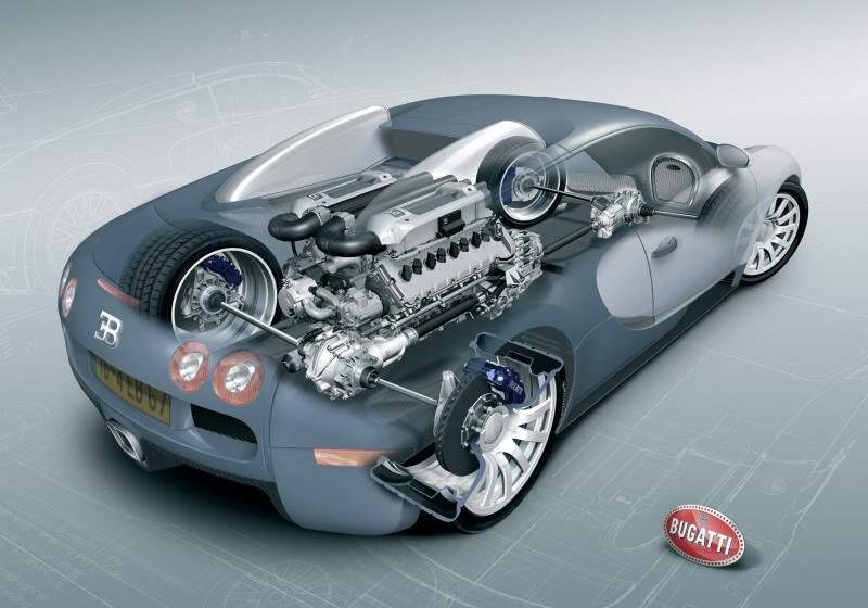
Another idea to throw out there but what about using the proven internals of a commercially available transfer case but machine a custom housing integrating the rotation reversal with spur gears. Two power outputs one forward one rearward. There is also the idea Nissan used in the GTR in which power goes to the rear via a drive line which powers the transaxle which has a forward output that transfers power to the front diff via a drive shaft parallel to the primary. You could mount the transfer case directly to the front diff keeping the transmission on the engine.
Another idea to throw out there but what about using the proven internals of a commercially available transfer case but machine a custom housing integrating the rotation reversal with spur gears. Two power outputs one forward one rearward. There is also the idea Nissan used in the GTR in which power goes to the rear via a drive line which powers the transaxle which has a forward output that transfers power to the front diff via a drive shaft parallel to the primary. You could mount the transfer case directly to the front diff keeping the transmission on the engine.
Thread Starter
Registered User
Joined: May 2013
Posts: 22
Likes: 0
I'd weld the spiders, or put a spool in the transaxle, maybe a locker in the rear diff, and an opened carrier front diff. You could set up and mod run 4wd s-10 front irs suspension in the front and rear of your car pretty cheaply and use the tierods in the rear for alignment adjustment.

In any event, I see no reason to put a locker in the rear diff. Limited slip is easy to get in a rear diff and I would definitely think that would be the right option. Also, that may not even be necessary or desirable if I keep the C5 Traction Control system. Can you explain why a locker in the rear of an AWD sports car would be desirable over limited slip or some other traction control system? I assume you are saying the locker could be engaged and disengaged manually by the driver? This one confuses me.
Actually, S-10 parts have been used in replicas before because they are stout and can have large disc brakes. That is definitely an option but it may be more expensive than using the existing C5 front suspension in conjunction with a diff like the Ford 8.8. My understanding is the C5 front spindles are easy to convert to use with axles since they are the same as the rears. Honestly, I haven't looked into this enough yet (it wasn't my biggest problem) so you may be right. Again, all options are on the table.
I think I understand your description but a basic diagram with dimensions would clarify a lot. It seems your CG is going to be very high with the crankshaft CL being so far above the rear axle CL. My reasoning for not using the corvette transmission is it doesn't make sense to reinvent the wheel to mount the transmission directly to the engine when GM has spent a ton of money figuring that out. Especially if you are going to come out of the tailshaft of the transmission with a drive line. If you are bolting the transfer case directly to the trans I'd bet there is more commercially available to remove the tailshaft from a 4L60 or 4L80 and mate it directly to a transfer case via the 4x4 OE applications.
Another idea to throw out there but what about using the proven internals of a commercially available transfer case but machine a custom housing integrating the rotation reversal with spur gears. Two power outputs one forward one rearward. There is also the idea Nissan used in the GTR in which power goes to the rear via a drive line which powers the transaxle which has a forward output that transfers power to the front diff via a drive shaft parallel to the primary. You could mount the transfer case directly to the front diff keeping the transmission on the engine.
Another idea to throw out there but what about using the proven internals of a commercially available transfer case but machine a custom housing integrating the rotation reversal with spur gears. Two power outputs one forward one rearward. There is also the idea Nissan used in the GTR in which power goes to the rear via a drive line which powers the transaxle which has a forward output that transfers power to the front diff via a drive shaft parallel to the primary. You could mount the transfer case directly to the front diff keeping the transmission on the engine.
I don't think the center of gravity is going to be any higher with either of the two main ideas than any other replica build out there do you? Most replicas use a Fiero, MR2 or Porsche rear or do something similar to what tonypaul did using a FWD treansaxle to drive the rear wheels. The CG would probably be a bit better with the first idea (using a V-Drive). Not sure if the difference is material or not for the kind of driving I will typically be doing. As always I am interested in hearing opinions.
As mentioned earlier in this thread. I really can't mount the t-case directly to the tranny for a number of reasons and I have no plans to run a drive shaft directly off the tranny and make a FWD car. [Unless I was able to pull off your custom t-case housing suggestion]
Are you building a replica? If not, what are you building? I did a search here to try to figure out your perspective but I couldn't find anything. Could you point me to a thread describing your build?
I actually thought of your suggestion to basically encapsulate the selected t-case internals into a custom housing which would also reverse the rotation but I figured it would probably be cost prohibitive. On the other hand, given that the V-Drive itself is going to run anywhere from $1,500 to $4,000 depending on what I get and the V-Drive option requires two extra connection points which waste space and money in additional parts, this is also definitely worth a look. Does anyone know of a shop that does this rare kind of work?
The Nissan GT-R is an amazing feat of engineering. I don't think I will be able to come anywhere near matching it with this home build. So you are saying in conjunction with creating a custom reverse rotation t-case, I mount it directly to the front diff? That does simplify things a bit. For one, there would be only two drive shafts (vs. up to four)! No small feat. It would also put that t-case somewhere where it will not conflict/interfere with the cab like I wanted. This would also probably allow me to use the C5 engine/tranny in their stock configuration including utilizing the torque tube. It would indeed be an elegant solution to a complicated problem. This is definitely worth looking into. Do you have a suggestion for the best way to mount the t-case directly to the front diff?
A big thank you to everyone for your ideas/suggestions. I think this it totally doable. Not sure how it is going to happen yet. I am still doing a lot of research at this stage.
Staging Lane
Joined: Jul 2012
Posts: 84
Likes: 0
From: Bakersfield, CA
My build is no where near as ambitious as yours from an engineering standpoint. There are pics of it in my garage gallery. The T-case would need some design work for sure but if it were my project I'd look into using parts of an existing t-case for inspiration as far as layout, oil capacity, shaft layout, lubrication concerns etc. If you run spur gears meshed the driven will be reverse rotation. If you need to keep the same rotation an idler or a chain drive like a FWD transmission uses would be tough enough. Mounting the t-case to the diff would be easiest with a diff housing that has a pinion that drops out like a 9" ford as it would have a flat plane with bolt bosses already in the design. A simple adaptor would be suitable to mount the housing. If you want to go that route I'd get a spicer power transmission parts book. You may even be able to mod a V drive to have fore and aft outputs instead of only one on the input side.
I've got nothing for your original question, but I always
thought it would be bad-*** to get a pair of cop Impalas,
put a V8 up front and a V8 out back and there's your
50/50 and 4 independent corners, with a whole mess of
power (and 4-wheel steering if you were up to that).
thought it would be bad-*** to get a pair of cop Impalas,
put a V8 up front and a V8 out back and there's your
50/50 and 4 independent corners, with a whole mess of
power (and 4-wheel steering if you were up to that).
Thread Starter
Registered User
Joined: May 2013
Posts: 22
Likes: 0
jimmyblue, Ha! Yeah, I guess it wouldn't get that great of gas mileage would it? Come to think of it, four wheel steering is something I should definitely throw into my project requirements. Why not? My requirements are already complicated enough people are saying it can't/shouldn't be done. If I am going to do the impossible anyway, I may as well go for broke right?
markbsae, your truck is really cool. Great job! I like what you are doing with it.
So to summarize where I am right now. We have two seemingly feasible ideas that meet the AWD requirements of this project:
1) Use a standard C5 drivetrain mounted backwards with an appropriate divorced AWD 1:1 t-case. I am leaning towards using the Borg Warner 4472 because it is cheap and widely available. I would also consider using the NP149 because it can handle a lot more torque but it is not as widely available and it is larger, heavier and more expensive. In order to fix the problem of having a default 65/35 front/rear power bias due to the reversed position of the t-case, either a V-Drive or a modification to the t-case would be necessary. I would prefer a modification to the t-case in order to reduce the number of components and simplify installation but to keep the costs down, I may not be able to do that.
Pros:
- Mechanical AWD, no extra electronics to worry about
- Optimum center of gravity due to position of engine, tranny & t-case
- Good weight balance front/rear
Cons:
- Multiple components required which may be difficult to fit
- Relatively expensive due to the power bias fix (V-Drive or modified t-case)
- The power bias fix may be noisy. The greater the angle between the V-Drive shafts, the quieter it will be
2) Use a FWD transaxle as a center differential. I would probably go with the 4T65E-HD and hope it could withstand the abuse I would be throwing at it. From what I can tell, this transaxle did not come in limited slip so I would have to add an aftermarket solution like a Quaife unit http://www.quaifelsd.com/ to make this work as I don't want to lock the center diff.
Pros:
- Mechanical AWD, no extra electronics to worry about
- Full time 50/50 front/rear power split without additional components
- Simple design with fewer parts
- Relatively cheap
Cons
- Gearing would be difficult to get correct since we would have to multiply the center diff gearing with the front/rear diff gearing
- May be a tight squeeze to get the rear driveshaft in
- Unable to use C5 4L60-E tranny
- Would need to figure out new tranny electronics
- May not be able to use the C5 LS1 without modifications. may have to go to an LS3/LS4
- The axle shafts of the transaxle would not be centered so I would have to offset the rear diff at the very least
- The open diff in the transaxle would be a problem. I would have to add a limited slip at an additional cost
- Center of gravity not as good as option #1
I am still leaning toward solution #1 because it will probably result in the best finished product and it may even end up being cheaper because I can use the C5 engine & tranny. However, I still haven't ruled out #2.
Regarding modifying the t-case for #1, I think this is doable. I have looked around and seen people doing custom stuff with t-cases - mostly for rock crawlers but the principals should be the same.
Regarding gearing for solution #2, I believe with custom transaxle chain gears this could work but as the tranny shifted, the ratio would change and I'm not sure how to calculate or deal with that. The only other way I can think of to solve this problem is use some kind of external gear reduction which I don't really have room for and it would increase the cost.
A possible third option I thought of is try to leverage a Torsen center diff like what the Audi's and VWs use. The older versions are mechanical with no electronics. I would have to figure out how to hook this up and I'm not sure how to do that because I don't fully understand how they work yet. Still looking into that option.
Last edited by BigPines; May 23, 2013 at 11:04 PM.
Thread Starter
Registered User
Joined: May 2013
Posts: 22
Likes: 0
I just found that Kevin Lyons (kevkev60 on this forum) built an amazing Diablo replica using pretty much the exact method I am leaning toward (#1 above). His version is not AWD since he says AWDs are "boring" to drive - so he didn't have a transfer case. However, he did use the C5 engine and tranny mounted backwards with a Casale V-Drive to get a driveshaft back to a C4 rear diff. He says it worked awesome! This is very encouraging. If I can't get the AWD to work for some reason, this is what I will do. Not a bad fall back position.