


How Boom tubes work?
Thread Starter
TECH Enthusiast
iTrader: (2)
Joined: Mar 2005
Posts: 624
Likes: 0
From: Trabuco Canyon, CA
I read in GM Hitech that a boom tube creates venturis that induce a scavenging effect. I tried to find out more specific technical information on this by searching here and the web, but was unsuccessful.
I know there are some real pro engineers in here, and I've got some real specific questions.
First my setup: I'm building an '03 vette longblock with all the usual bolt-ons, a 4.08 rear, and after I get the flow numbers for the heads I'm expecting a healthy cam around 230. This is for my street car/toy with a full cage that I plan on dragging out to every motorsport event that my time and $ will allow. My original intention was:
1.75" primary HEADERS w/ 3" collectors
->
X-pipe
->
dual 3" Catalytic converters
->
dual 3" perforated core, glass pack, RV mufflers (as long as possible, hoping to fit dual 31"x7"). [Small 3" resonator mufflers B4 or after?]
->
Dual Side exit Pipes (Boom Tubes?)
Edit: filling in answers as they come:
?????????????????????????????????????????????????? ????????????
Do the tubes have to be cut on a slant to achieve/enhance any scavenging effect?
Is it still as affective at the end of a full exhaust system? ANYONE????
Does the length of the boom tubes matter? Longer = more scanvenge/balance effect
Do they increase or decrease sound at all? Longer = Quieter (at least a little)
Is their performance affected by their location relative to the back wheel or the vertical plane of the side of the car? At the very least the frequencies that are enhanced are affected.
Are two boom tubes on opposite sides of the car as affective as a single larger one on one side? A single larger one could create more downforce.
?????????????????????????????????????????????????? ?????????????
& Any recommendations/advice on the rest of my proposed system are sought and welcome
Last edited by GIGAPUNK; Jun 9, 2006 at 08:19 PM.
TECH Fanatic
Joined: Jun 2002
Posts: 1,979
Likes: 3
From: Upstate NY
No offense, but you're doing fine up to the cats. Behind them you might want to look at a different setup.
I'm not sure what "venturi effect" boom tubes have since venturi implies reducing the cross-section rather than increasing it drastically. With an increase in pipe size (boom tube?) the flow slows down, and accordingly the pressure at that point increases. I don't want an increase in the (back)pressure at the end of my tailpipes, and if I did, I could just stuff a potato in the pipe.
Look for free flowing mufflers. 31 inch long RV muflers might not be the best for flow and low weight. Consider any of the Dynomax Ultraflow or similar Magnaflow 3 in. straight-thru styles. Dynomax quotes flow rates of their better mufflers. You coud also use small "bullets" after the mufflers as resonators to get rid of some of the more objectionable frequencies. Some trial and error for best placement might be needed.
Another aproach is that used by Corsa where they use resonance cancelling techniques with very little flow restriction. Try their website. This technology was developed in the 60s by at leat one OEM but used sparingly.
One last thought: Look at the 2006 Z06 (LS7) exhaust with 3 inch duals with mufflers that have two selectable flow paths. They use a valve to direct the flow to the lowest restriction (loudest) path under high exhaust flow conditions like full throttle and rpm above 3500. This system will support a lot more than the 505 hp now offered. You could rig a throttle switch up to open the system at wide open throttle. I think we'll start seeing more of this
My $.02
Thread Starter
TECH Enthusiast
iTrader: (2)
Joined: Mar 2005
Posts: 624
Likes: 0
From: Trabuco Canyon, CA
From an article in GM Hitech:
"The side-exit Dr. Gas Boom Tube Mufflers and X-pipe are identical to those used on the Winston Cup cars and Craftsman truck series. They provide a slight decibel reduction while using Naca ducts to reduce more backpressure than dumps."
where are the naca ducts? in the deviding runners?
"The Boom Tubes are designed merely to increase exhaust gas velocity using Naca ducts (which create a sort of Venturi effect) as opposed to straight-piping, and offer only a slight decibel reduction."
The boom tubes are the fancy flat exhaust tip. Dr. Gas is famous for making them, usually placed immediately after his x-pipes:
Last edited by GIGAPUNK; May 6, 2006 at 02:14 PM.
Thread Starter
TECH Enthusiast
iTrader: (2)
Joined: Mar 2005
Posts: 624
Likes: 0
From: Trabuco Canyon, CA
Old SStroker. These were the mufflers I was looking at:
http://store.summitracing.com/partde...5&autoview=sku
and only $52!
They actually are dynomax. Presuming that they are a single perforated tube all the way through (if any one can confirm or disprove this I'd appreciate it because dynomax also has a line of perforated/chambered mufflers), I was under the impression that a perforated tube flowed almost equally well to an uperforated tube. And that having a longer muffler would have no adverse affects on flow, but would provide greater sound suppression. Granted they may be heavy, I can't get anyone at dynomax or summit to quote me a weight. A quiet exhaust is very important to me, (I've already lost my liscence once for too many tickets: Me being an idiot 90%, Flowmaster 10%) So even if they are heavy at least the weight is in the best possible location
The dyno max mufflers above are actually 3.5" in and out C/C. I've thought about using 3.5" collectors --> x --> cats to these -->gentle taper to 3.0" and then bullets --> exit.
Several sources I trust have said that at the VERY BACK of an exhaust system it is safe to step down a little bit in size because the exhaust gasses have cooled enough (therefore condensed enough) to not be restricted by a slightly small pipe. Perhaps your venturi idea plays in here as well as necking down would create a lower pressure zone by picking up the velocity. Plus if I ever decide to go turbo I already have a huge system waiting for it.
I also have been told and believe, that it is difficult to get a street/quiet system out of a true 3.5" system that goes from collector to exit.
And thanx for the heads up on Corsa's techniques, Looks like I've got some more reading!
Last edited by GIGAPUNK; May 6, 2006 at 02:18 PM.
TECH Fanatic
Joined: Jun 2002
Posts: 1,979
Likes: 3
From: Upstate NY
Oops! I wasn't thinking of NASCAR-style boom tubes but the style seen on the street. I apologize for thinking that of you, GIA. 
If I recall, Cup cars try to dump their exhaust in a low pressure area of the car when it's at speed. Perhaps they are creating that low pressure area by vehicle shape.
If I recall, Cup cars try to dump their exhaust in a low pressure area of the car when it's at speed. Perhaps they are creating that low pressure area by vehicle shape.
You'd have a really hard time running those on the street because there wide and hold alot of heat under the car. The floor boards and rockerpanels of our race trucks would show sighns if the heat and smoke eventually burning the paint off...Not a good idea with carpet and a fiberglass body
Trending Topics
Thread Starter
TECH Enthusiast
iTrader: (2)
Joined: Mar 2005
Posts: 624
Likes: 0
From: Trabuco Canyon, CA
CTS thanx for the input. It's always good to get real practical know how in here!
Fortunately there's no carpet in my ride and there is a decent amount of airspace below the rear seat just in front of my rear tire. The heat issue sounds like a good reason to go with two out opposite sides though. Also I'm dealing with a 1998 240sx that is all steel. Sounds like the side, stock ground effects are gunna have to go. I don't much like that melted plastic smell!
I noticed that Dr. Gas reccomends coating them. Now we know why.
LS1 Tech Stories
The Best V8 Stories One Small Block at Time

Topdon ONE vs. Artidiag 800 BT2: Which is the Diagnostic Tablet For You?
Pouria Savadkouei
Gas Monkey Built a 6-Wheel Ferrari Testarossa With a Corvette LT4 Engine
Verdad Gallardo
7 Most Reliable High-Performance Engines GM Has Ever Built
Verdad Gallardo
Amazing '71 Camaro Restomod Is Modern Muscle Car Under the Skin
Verdad Gallardo
6 Common C5 Corvette Failures and What's Involved In Repairing Them
Pouria Savadkouei
Retro Modern Bandit Pontiac Trans AM Comes With Burt Reynolds' Autograph
Verdad Gallardo
Top 10 Greatest Cadillac V Series Performance Models Ever, Ranked
Pouria Savadkouei
Top 10 Most Powerful Chevy Trucks Ever Made!

Hennessey's New Supercharged Silverado ZR2 Has 700 HP
Verdad Gallardo
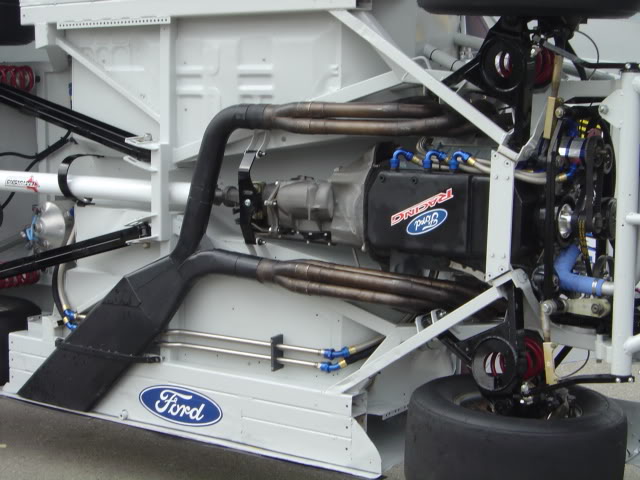
Theres a few different types of systems that teams will run..the one pictured is not a boom tube but a Y speedway fan, boom tubes made of 3x4 oval tube are hardly ran anymore also a x pipe or H pipe is common..Teams will make the system as large as possible for tracks like Daytona and Taladega and they will almost act like a belly pan belive it or not types or exhaust will show some differences in the wind tunnel.Open chambers in the middle of the "Y" are common also Some of the old school stuff will have multiple x's in it to suck the exhaust out very important on plate motors.And these things are very heavy an have to have multiple mounts and saftey straps.
Looking at that picture I get a kick out of seeing an old T-10 tranny those things havent been ran in 20 years...
Looking at that picture I get a kick out of seeing an old T-10 tranny those things havent been ran in 20 years...
Thread Starter
TECH Enthusiast
iTrader: (2)
Joined: Mar 2005
Posts: 624
Likes: 0
From: Trabuco Canyon, CA
So, I found these
Boom tubes
2 1/2 x 4" ID oval inlet
11" x 1 1/4" outlet
35 3/4" to 42" from center of inlet to ends
These came from a NEXTEL cup team
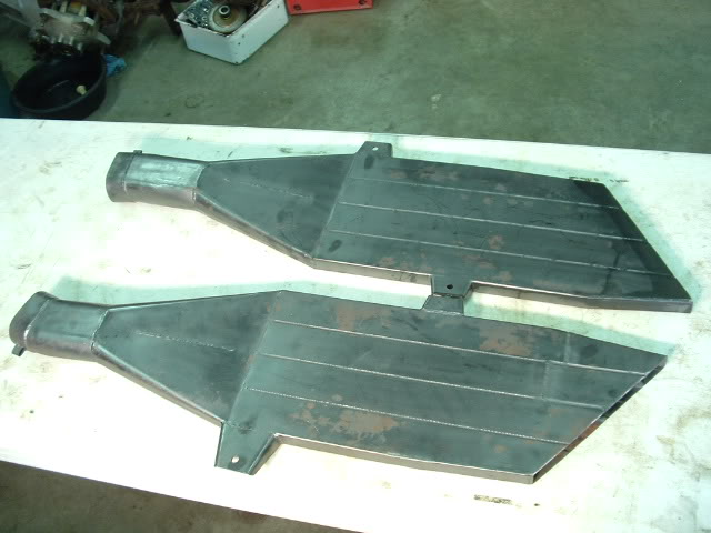
What kind of track would they be used on?
2.5x4" inlet! That equates to like a 4.1" round tube, dual!!! Are nextel exhaust system actually that big?
Could these work at the end of an LS1 system that expanded out at say 10 degrees from 3"or 3.5 " to 4"? I know that a gradual expasion like that is best for airflow when you are trying to get optimum flow from/to big catalytic converters, but would you get the expansion = high pressure "plug" that oldsstroker was threorizing about? Or would an abrupt change in size work better (like a step hedder)?
Boom tubes
2 1/2 x 4" ID oval inlet
11" x 1 1/4" outlet
35 3/4" to 42" from center of inlet to ends
These came from a NEXTEL cup team
What kind of track would they be used on?
2.5x4" inlet! That equates to like a 4.1" round tube, dual!!! Are nextel exhaust system actually that big?
Could these work at the end of an LS1 system that expanded out at say 10 degrees from 3"or 3.5 " to 4"? I know that a gradual expasion like that is best for airflow when you are trying to get optimum flow from/to big catalytic converters, but would you get the expansion = high pressure "plug" that oldsstroker was threorizing about? Or would an abrupt change in size work better (like a step hedder)?
Originally Posted by CTSmechanic
You'd have a really hard time running those on the street because there wide and hold alot of heat under the car. The floor boards and rockerpanels of our race trucks would show sighns if the heat and smoke eventually burning the paint off...Not a good idea with carpet and a fiberglass body
TECH Fanatic
Joined: Jun 2002
Posts: 1,979
Likes: 3
From: Upstate NY
Originally Posted by GIGAPUNK
So, I found these
Boom tubes
2 1/2 x 4" ID oval inlet
11" x 1 1/4" outlet
35 3/4" to 42" from center of inlet to ends
These came from a NEXTEL cup team

What kind of track would they be used on?
2.5x4" inlet! That equates to like a 4.1" round tube, dual!!! Are nextel exhaust system actually that big?
Could these work at the end of an LS1 system that expanded out at say 10 degrees from 3"or 3.5 " to 4"? I know that a gradual expasion like that is best for airflow when you are trying to get optimum flow from/to big catalytic converters, but would you get the expansion = high pressure "plug" that oldsstroker was threorizing about? Or would an abrupt change in size work better (like a step hedder)?
Boom tubes
2 1/2 x 4" ID oval inlet
11" x 1 1/4" outlet
35 3/4" to 42" from center of inlet to ends
These came from a NEXTEL cup team
What kind of track would they be used on?
2.5x4" inlet! That equates to like a 4.1" round tube, dual!!! Are nextel exhaust system actually that big?
Could these work at the end of an LS1 system that expanded out at say 10 degrees from 3"or 3.5 " to 4"? I know that a gradual expasion like that is best for airflow when you are trying to get optimum flow from/to big catalytic converters, but would you get the expansion = high pressure "plug" that oldsstroker was threorizing about? Or would an abrupt change in size work better (like a step hedder)?
The inside area of the 11 x 1-1/4 is just about the same a s 4.00 round tube, but the surface area of all the sides and dividers is more like the surface area of a 9-3/4 round tube! All that surface causes flow restriction, so the cross-sectional area seems just about right for the inlet.
My "plug" comment assumed a rapid and extreme change in section, like 3 in tube dumping into a 5 inch tube with no transition. That really doesn't apply here.
The gradual transition from round/oval to flat should keep the flow attached pretty well and cause almost no backpressure. The only real reasons I see for these flat outlets on a street car are the cool factor and ground clearance for a very low stance. Ground clearance is critical on the Cup car as well as the aero effect the flat tubes might provide. I'm fairly confident that various outlet shapes, positions and even angle of attack are tested in the tunnel as CTS said. It seems they might be a good way to put (ballast)weight very low on the vehicle if you omade them out of thick steel. NASCAR probably has a max. steel gage for them! 1/8 inch thick ones would weigh about 40 pounds. If you made them from 1/4 inch thick steel and thinned it out near the ends to look like thinner sheet metal, you could get maybe 75-80 pounds a couple inches off the pavement. That helps drop CG height. Nah, they wouldn't try that.
You mentioned using smaller pipes the farther away from the engine you get because the temp is cooling, the gasses are becoming denser and need less flow area. Yes, of course. A large temperature drop occurs across mufflers, especially 31 inch long ******. Depending on your fwhp, you might consider dropping from 3 inch to 2.5 inch after the last major bend beyond the muffler outlet. This will be a little quieter. You could use smaller "boom tubes" also, say 9-1/2 x 1-1/4 or thereabouts.
Last edited by Old SStroker; May 8, 2006 at 08:03 AM.
I belive those pictured are Superspeedway pipes...they cah unbolt the tips from a x pipe to increase or decrease extersions off the headers.those right there have a little a aero in'em.As far as weight I dont belive there can be a material to thick everything on the cars are desighned to be as lite as possible everything to the engine tail pipes and suspension..The frame rails inwhich the exhaust is bolted to holds tungsten blocks to be used as ballast.You want to be able to plave that weight anywhere you need to to achive the proper nose weight or subtract nose weight...weh ad a car built a few years ago that required almost 500 pounds of ballast once it was completly assembled...good thing she did'nt make it to the end without crashin or we would of had some explaining to do...
Teching In
Joined: Jan 2006
Posts: 18
Likes: 0
From: ShenZhen, China
I always considered them a necessary evil in the circle track days for getting more ground clearance in the turns on speedways.
Dr. Gas and BSR probably have a lot of info available about the outlet design and advantages / tuning, but my guess is that you will not see anything at normal highway speeds. Should be loud though...
Phase
Dr. Gas and BSR probably have a lot of info available about the outlet design and advantages / tuning, but my guess is that you will not see anything at normal highway speeds. Should be loud though...
Phase