
basement 4l60e buildup (photos)
 02-01-2007, 09:19 PM
#21
Launching!
iTrader: (1)
Join Date: Aug 2002
Location: Tulsa, OK
Posts: 246
Likes: 0
Received 0 Likes
on
0 Posts

I have rebuilt mine a couple of times, mainly due to broken accumulator spring and cracked piston. This caused the 3-4 clutchs to go bad. The easy part is taken them apart, the more difficult part is putting them back together. Mylar (sp?) sheets are wonderful for helping installing new seals. The 4 teflon rings are fun as well. Looks like you are doing a very good job keep up the great work! 
 02-11-2007, 04:59 PM
#22
Launching!
Thread Starter
iTrader: (2)
Join Date: May 2005
Location: Rochester Mn
Posts: 285
Likes: 0
Received 0 Likes
on
0 Posts
Ladies and gents...
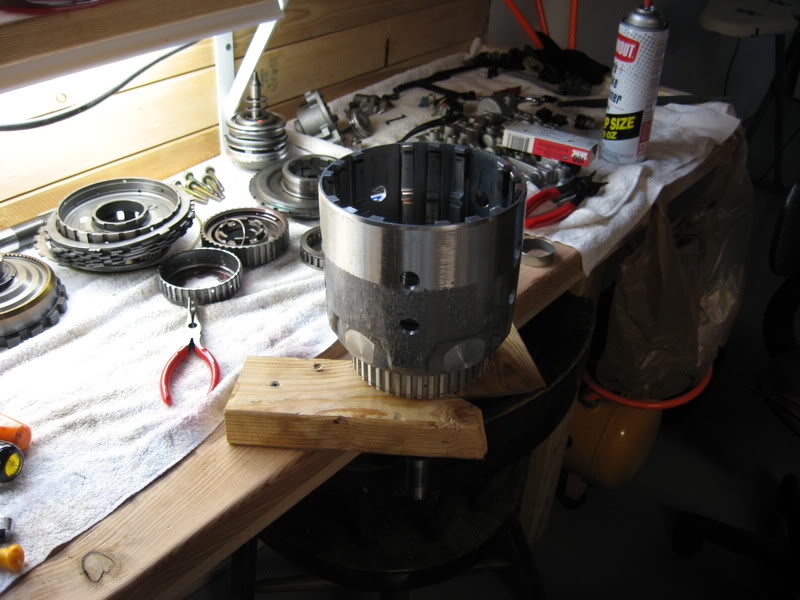
Took the low - reverse, and input drum apart today. Took some more pictures, I think I figured out why this trans was taken out of the car it was in.
Heres the low/reverse drum. Theres a plastic thrust washer on top. Take that off and flip it over. Then pull the extra grande snap ring.
Reach in and grab all the clutches and metals you can get ahold of. The pressure plate will be the large metal piece that comes out first. These look nice, they still have their original writing on them!
The bronze bushings in the drum look nice too.
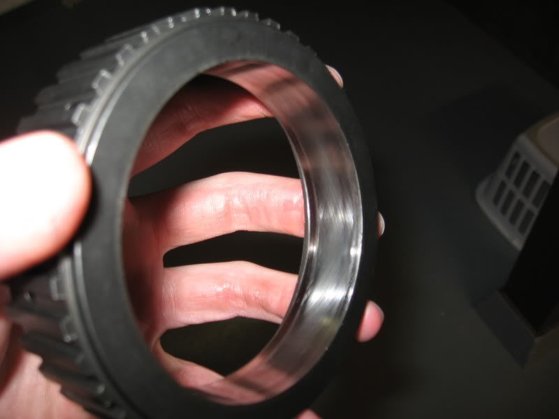
The area of the drum that the band grabs looks nice and smooth as well. Closest thing to a real straight edge I have...
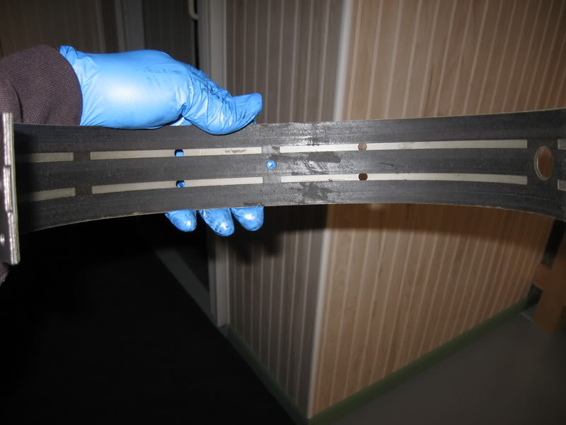
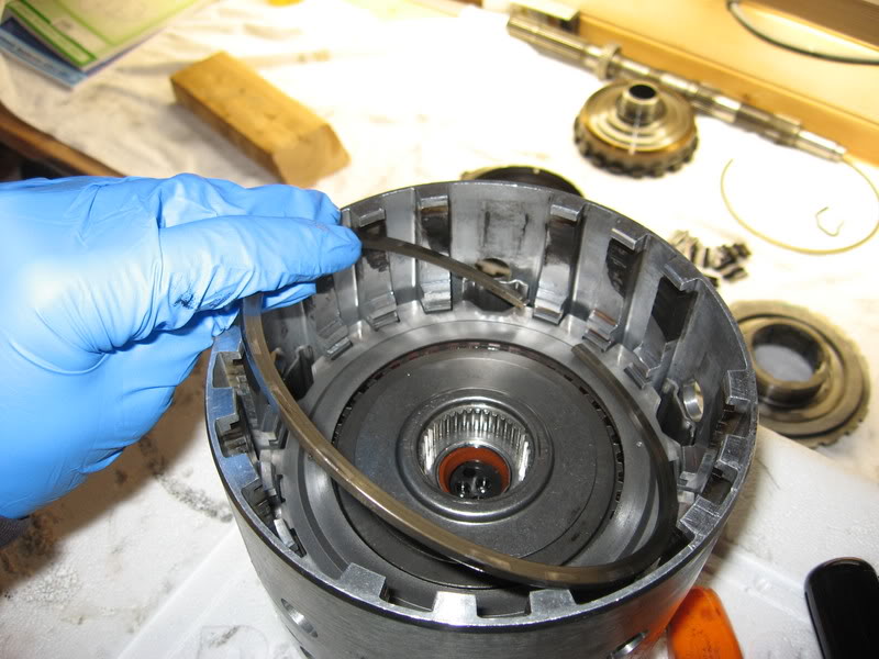
Here's a quick shot of the band, which has a few rips.
You may have noticed that I chose to leave the pistons and junk in the bottom of the drum. I figured the rest of the piece looked good so I'd leave it alone for now.
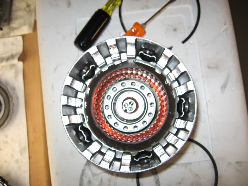
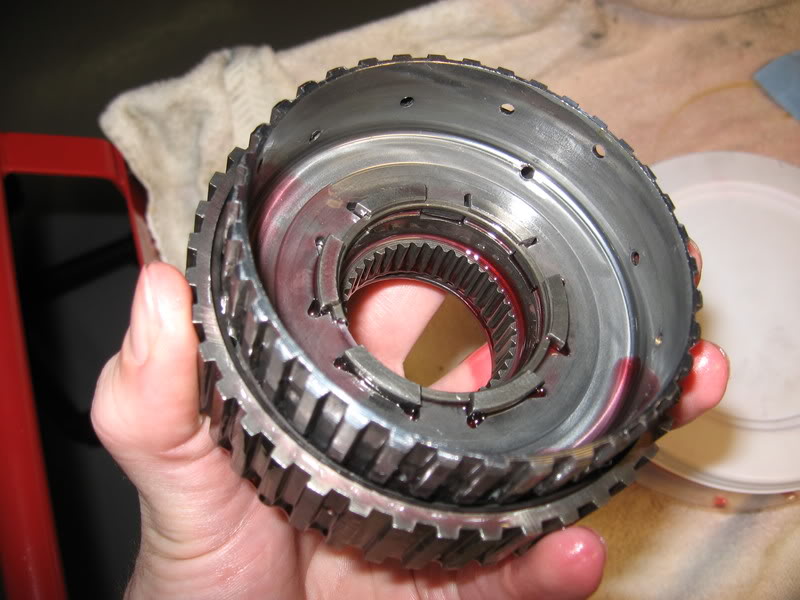
Next is the input drum (which houses the forward clutches, and 3/4 clutches).
I just punched a hole in a foam cooler and worked from there. Use a magne to pull the thrust bearing and endplay (selective) washer.
Selctive washer (GM has a sense of humor)
Took the low - reverse, and input drum apart today. Took some more pictures, I think I figured out why this trans was taken out of the car it was in.
Heres the low/reverse drum. Theres a plastic thrust washer on top. Take that off and flip it over. Then pull the extra grande snap ring.
Reach in and grab all the clutches and metals you can get ahold of. The pressure plate will be the large metal piece that comes out first. These look nice, they still have their original writing on them!
The bronze bushings in the drum look nice too.
The area of the drum that the band grabs looks nice and smooth as well. Closest thing to a real straight edge I have...
Here's a quick shot of the band, which has a few rips.
You may have noticed that I chose to leave the pistons and junk in the bottom of the drum. I figured the rest of the piece looked good so I'd leave it alone for now.
Next is the input drum (which houses the forward clutches, and 3/4 clutches).
I just punched a hole in a foam cooler and worked from there. Use a magne to pull the thrust bearing and endplay (selective) washer.
Selctive washer (GM has a sense of humor)
02-11-2007, 05:00 PM
#23
Launching!
Thread Starter
iTrader: (2)
Join Date: May 2005
Location: Rochester Mn
Posts: 285
Likes: 0
Received 0 Likes
on
0 Posts
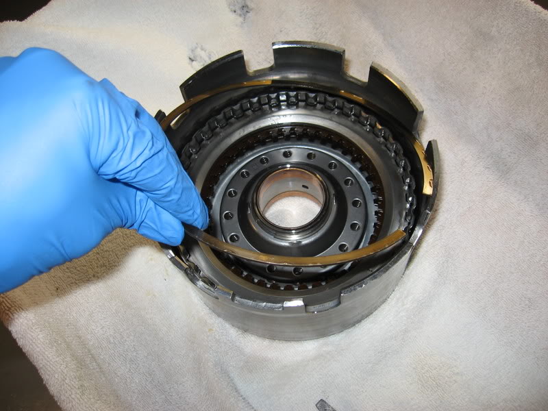
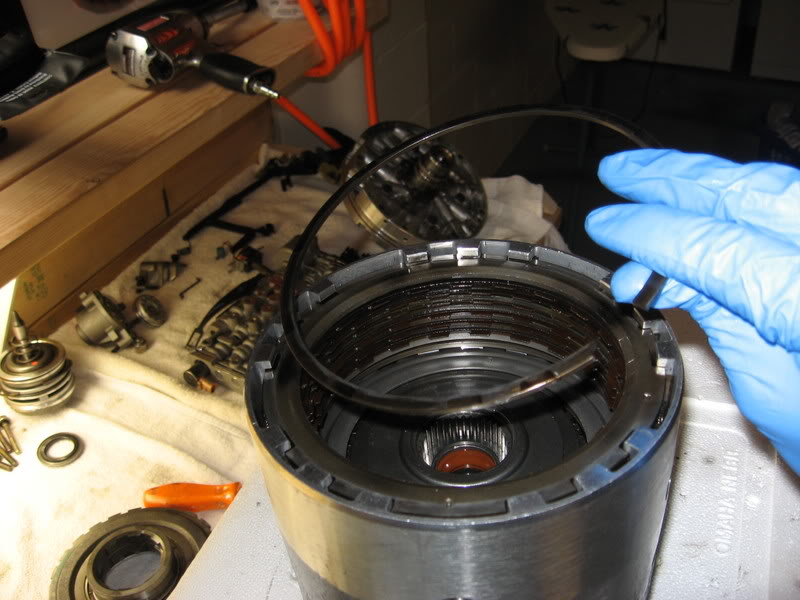
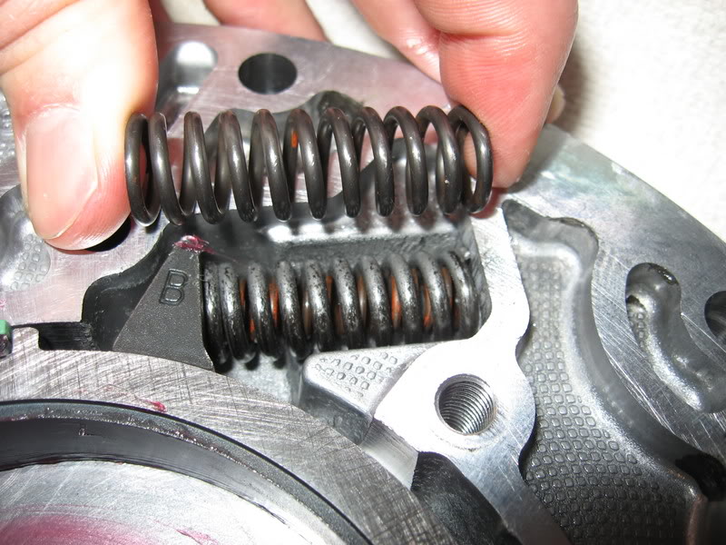
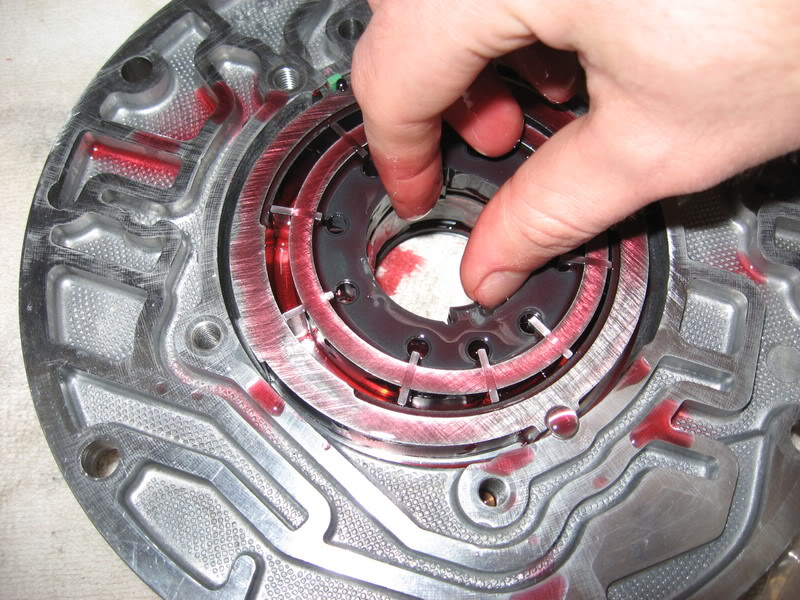
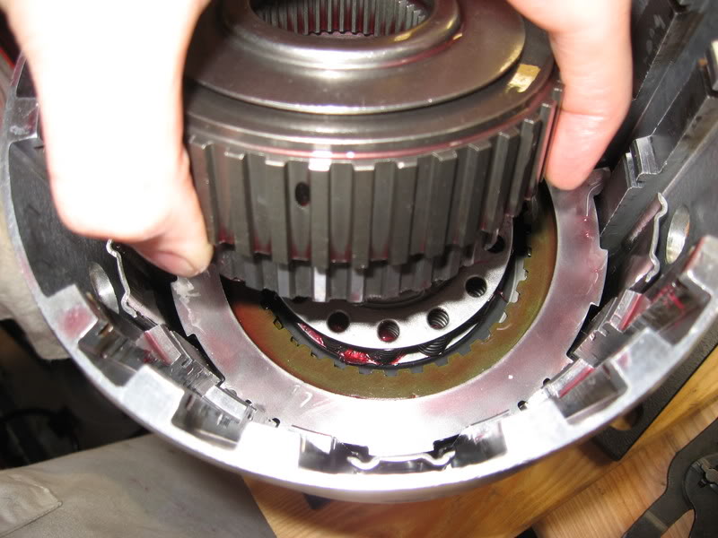
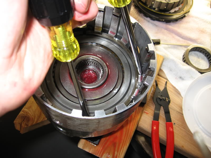
Here I popped out the snap ring to pull the 3/4 clutches. Just use a big flat blade.
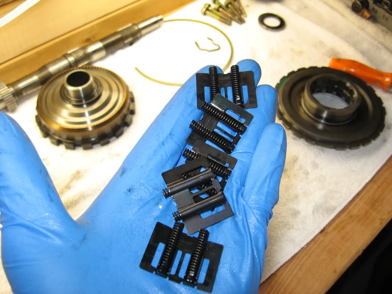
Grab these boost springs (5) from around the 3/4 clutches and put them in a safe place.
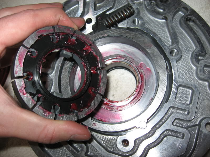
Reach in and grab the 3/4 clutches and pull them out.
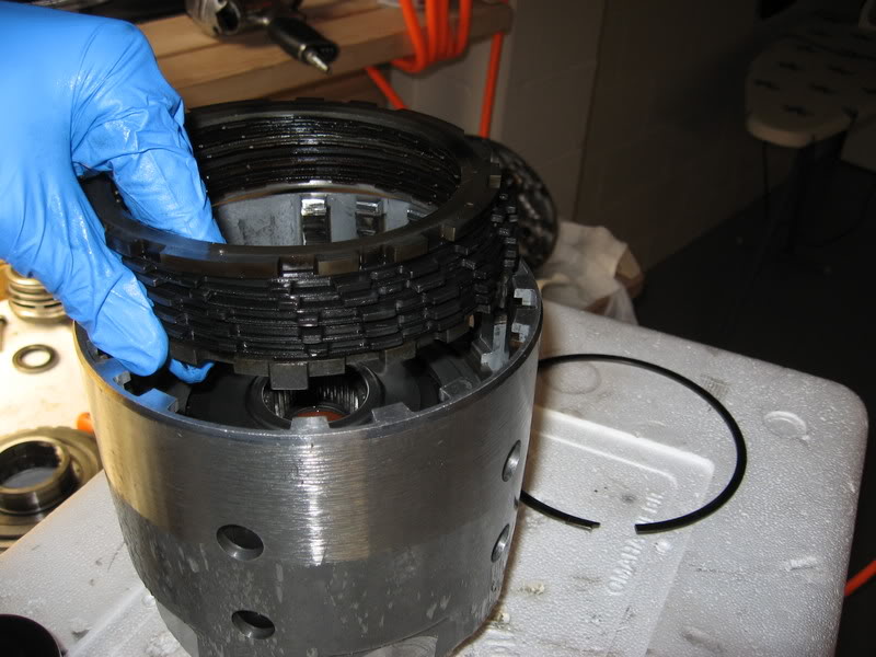
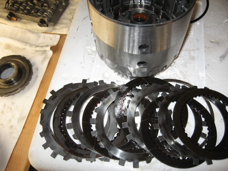
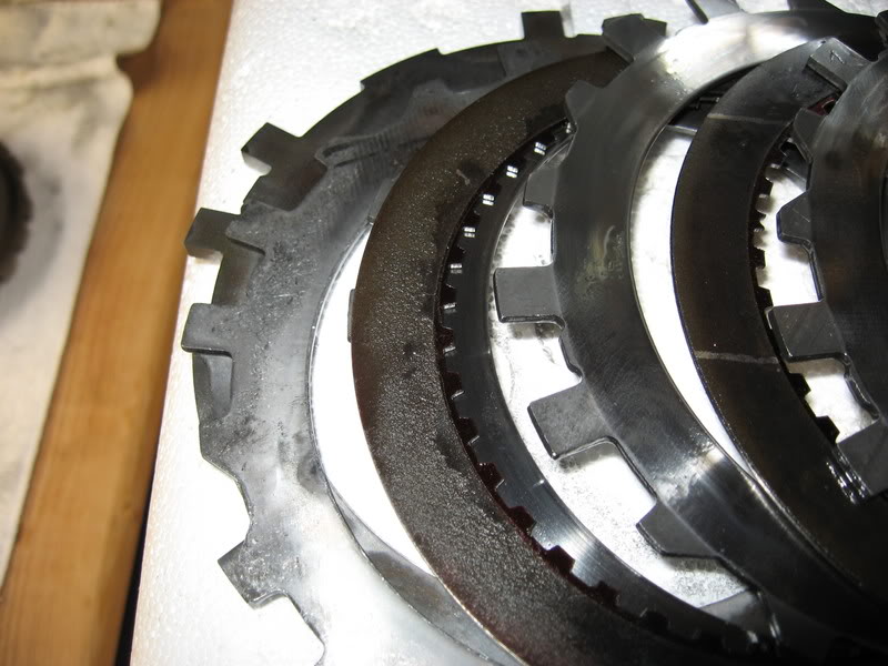
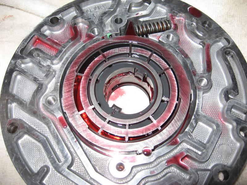
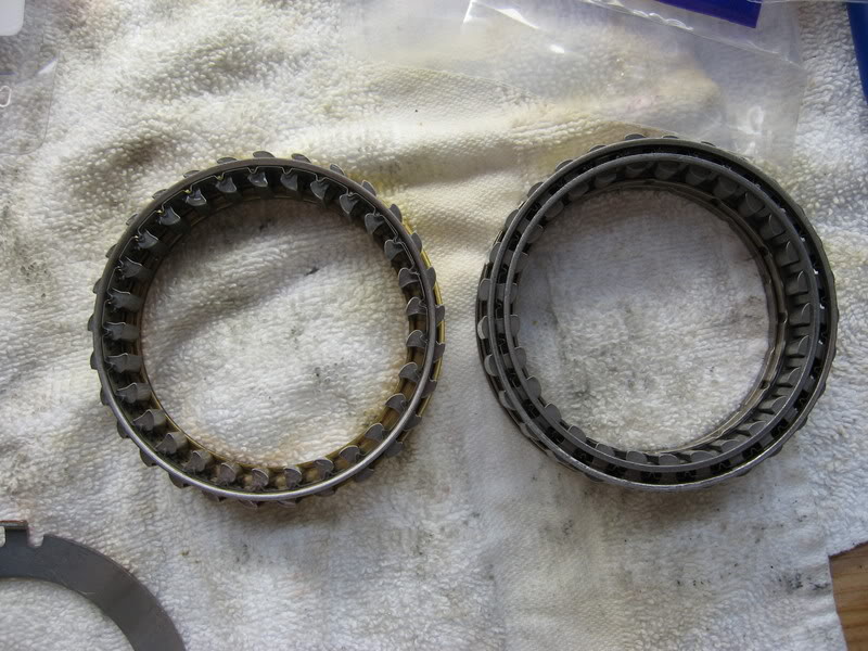
Here I've layed the clutches out so you can see how shitty they are.
They've alse beat on the input drum itself. There are some marks and nicks in the drum as seen.
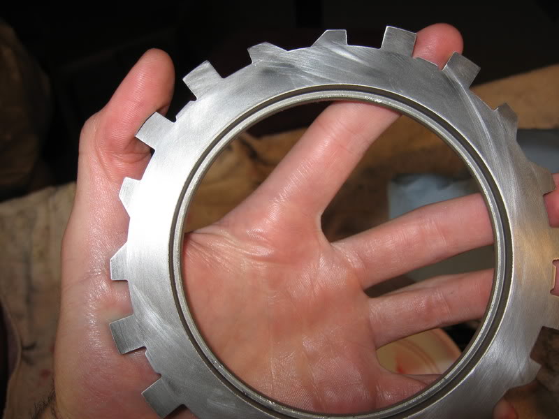
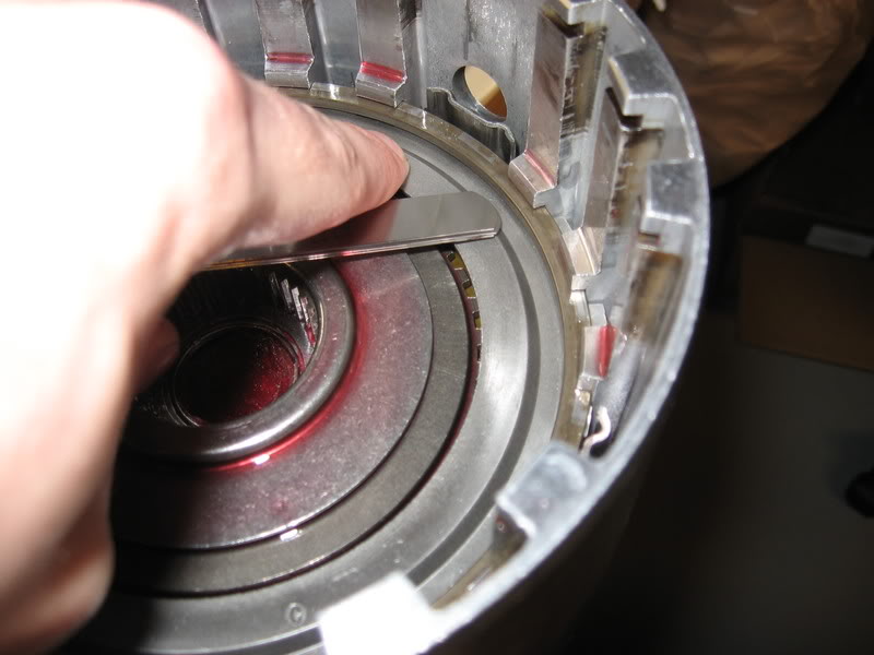
Next step is to pull the second big snap ring that holds the forward clutches.
In this picture you can also see the orange oil seal and thrust bearing which I put in a safe place.
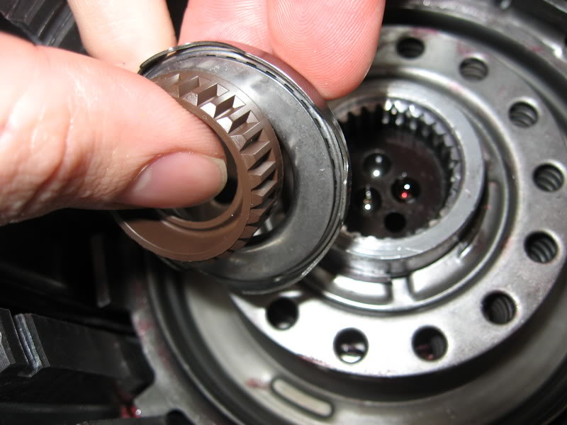
Pull out the input sprag and the forward clutch pressure plate together.
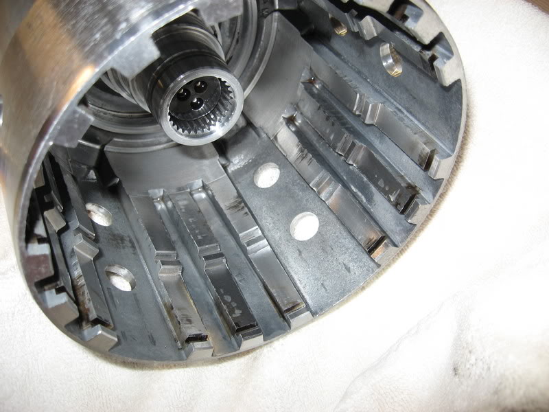
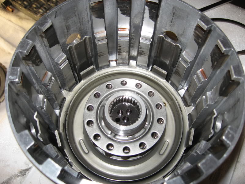
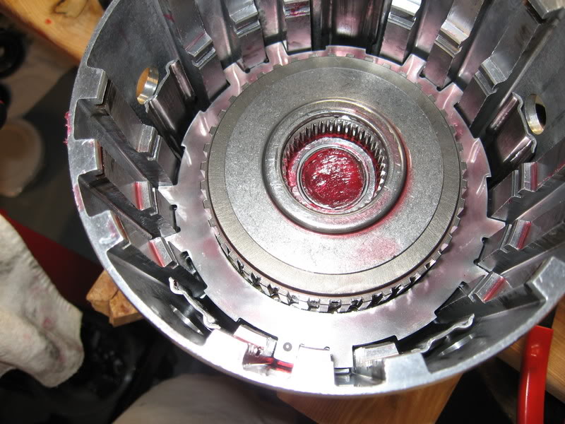
Here's a straight on shot into the drum while the forward clutches are still in it
(notice the two different sizes).
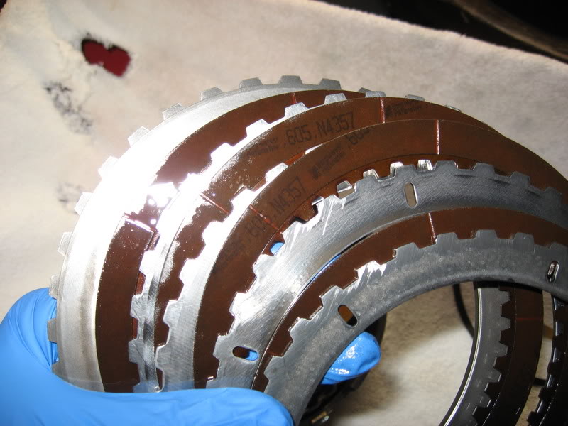
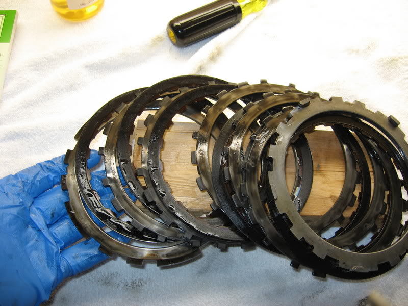
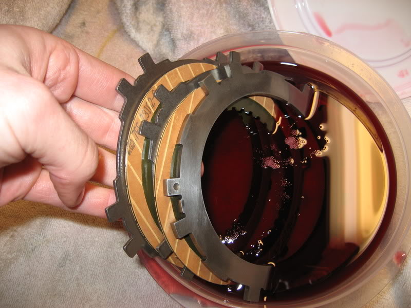
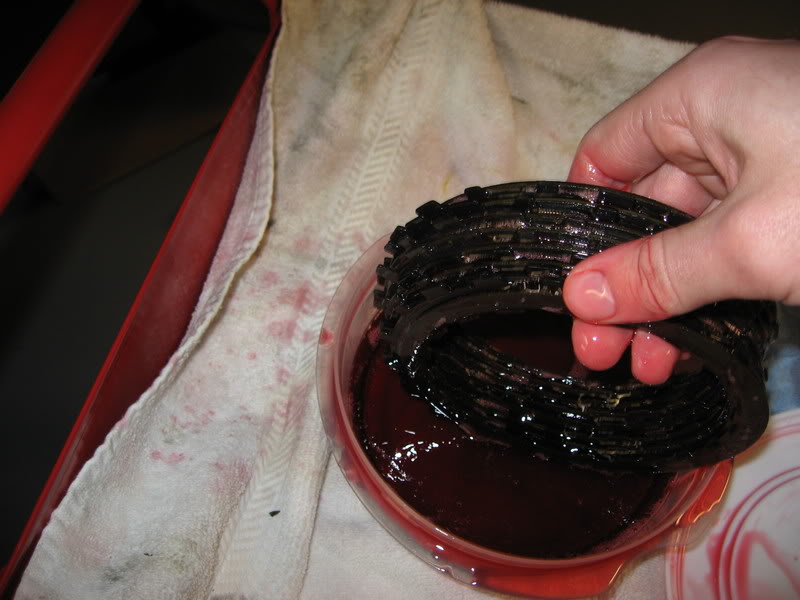
I layed the forward clutches out so you can see how wrecked they look. They're pretty much all black and a few are pitted. All the steels look like ***.
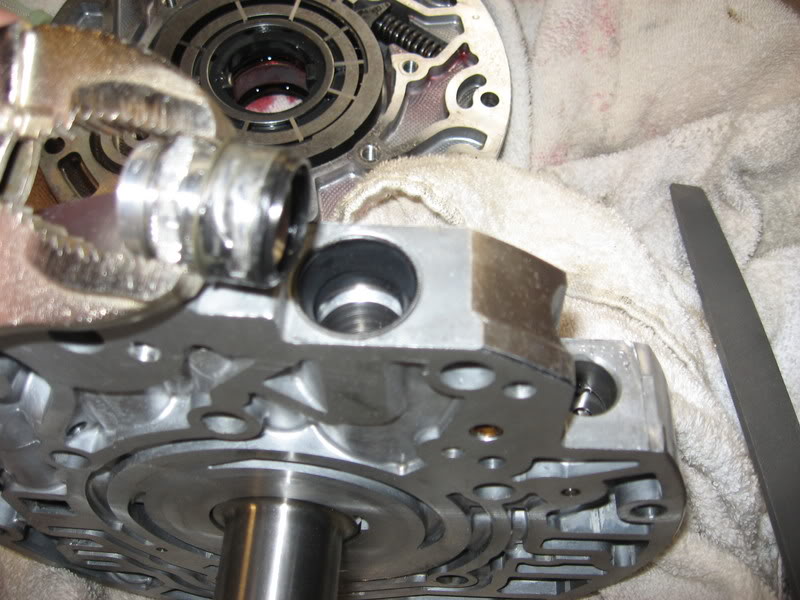
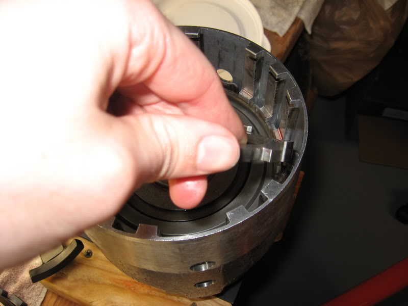
You'll need some tools to pull the pistons out of the back of the drum. These are kind of expensive so you may want to improvise
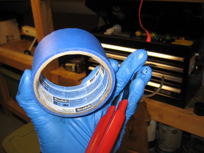
Pull the snap ring by placing your masking tape on the spring, pushing really hard and nabbing that bastard snap ring. Finish by banging the drum on the ground (nicely) to get the candy.
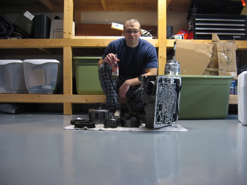
Finish by having a Premium Grain belt
I'll be ordering a kit next - now that I see what parts of the trans need to be addressed.
I apologize for the intervals between my posts, I'm trying guys!
~Nick
Grab these boost springs (5) from around the 3/4 clutches and put them in a safe place.
Reach in and grab the 3/4 clutches and pull them out.
Here I've layed the clutches out so you can see how shitty they are.
They've alse beat on the input drum itself. There are some marks and nicks in the drum as seen.
Next step is to pull the second big snap ring that holds the forward clutches.
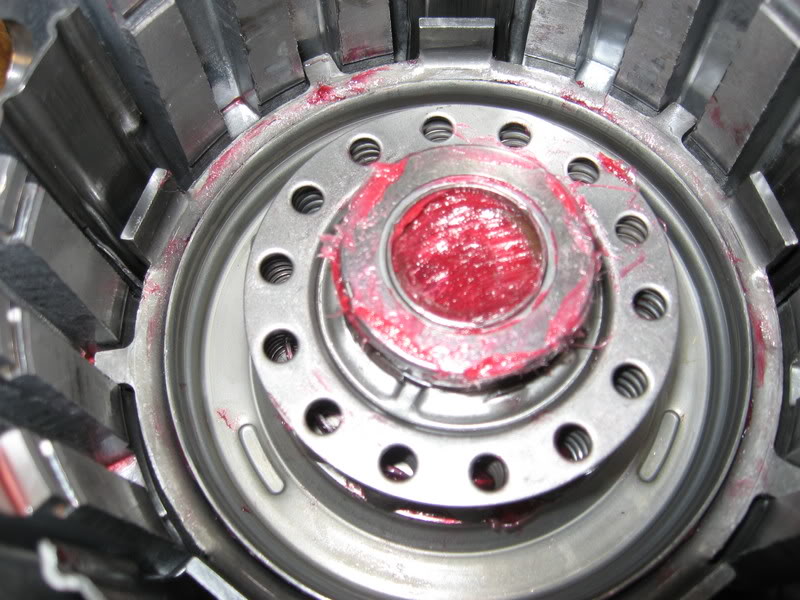
In this picture you can also see the orange oil seal and thrust bearing which I put in a safe place.
Pull out the input sprag and the forward clutch pressure plate together.
Here's a straight on shot into the drum while the forward clutches are still in it
(notice the two different sizes).
I layed the forward clutches out so you can see how wrecked they look. They're pretty much all black and a few are pitted. All the steels look like ***.
You'll need some tools to pull the pistons out of the back of the drum. These are kind of expensive so you may want to improvise
Pull the snap ring by placing your masking tape on the spring, pushing really hard and nabbing that bastard snap ring. Finish by banging the drum on the ground (nicely) to get the candy.
Finish by having a Premium Grain belt
I'll be ordering a kit next - now that I see what parts of the trans need to be addressed.
I apologize for the intervals between my posts, I'm trying guys!
~Nick
02-11-2007, 07:14 PM
#24

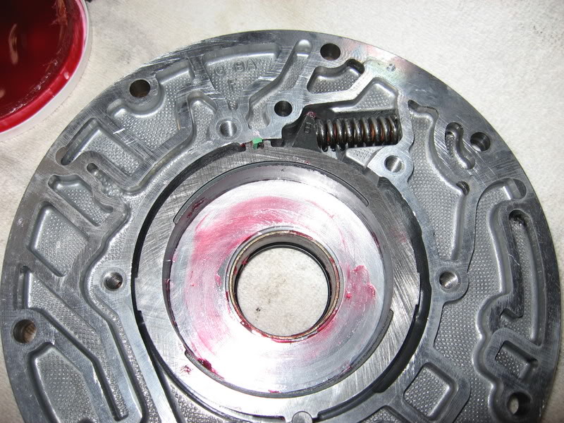
I was reading a ATSG book and it said to leave out the boost springs for a better 2-3 shift.Has anybody done that?
As many of the LS1 people I have noticed tend to do
__________________

Last edited by Ragtop 99; 11-23-2007 at 01:28 PM.
 02-13-2007, 12:23 AM
#25

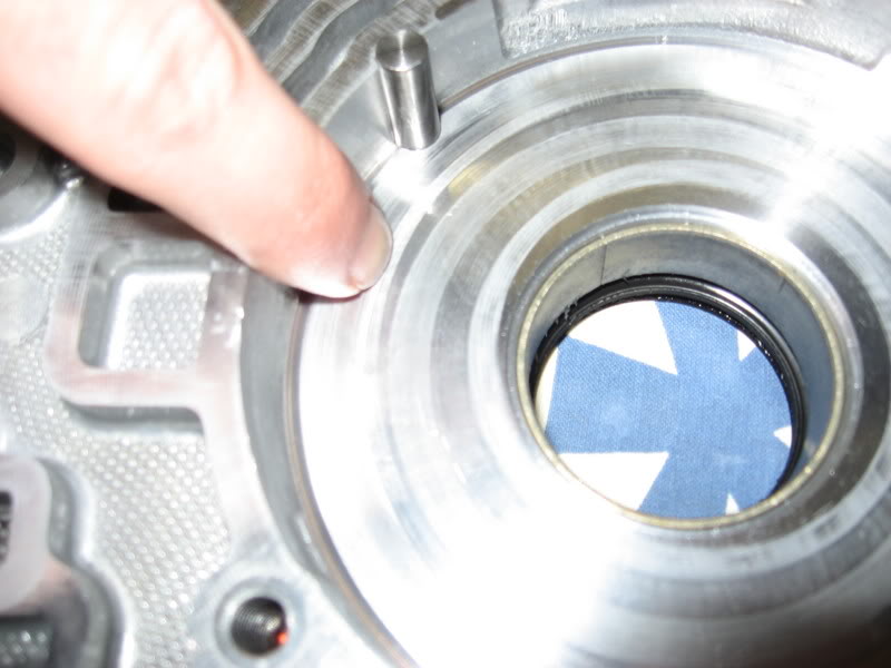
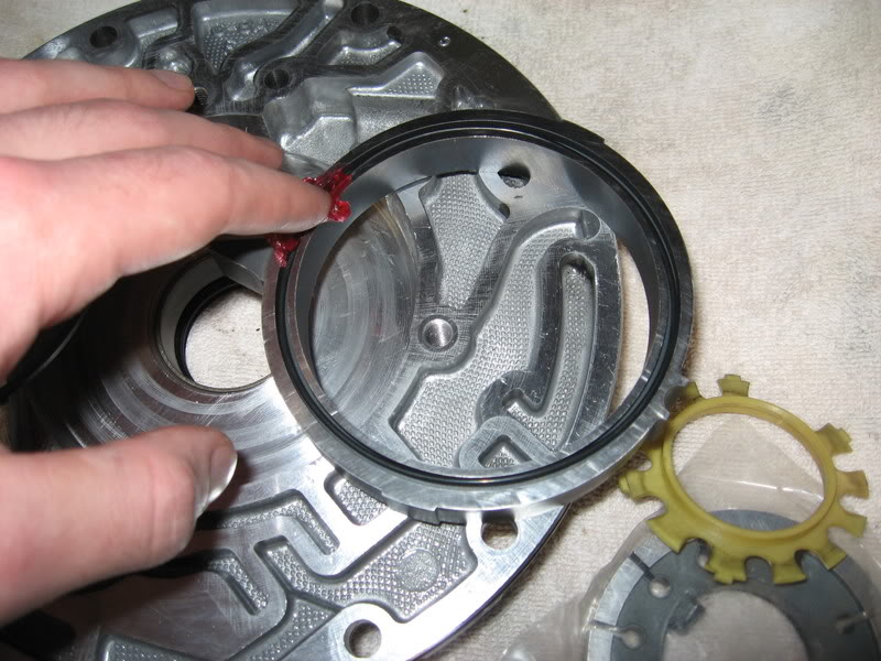
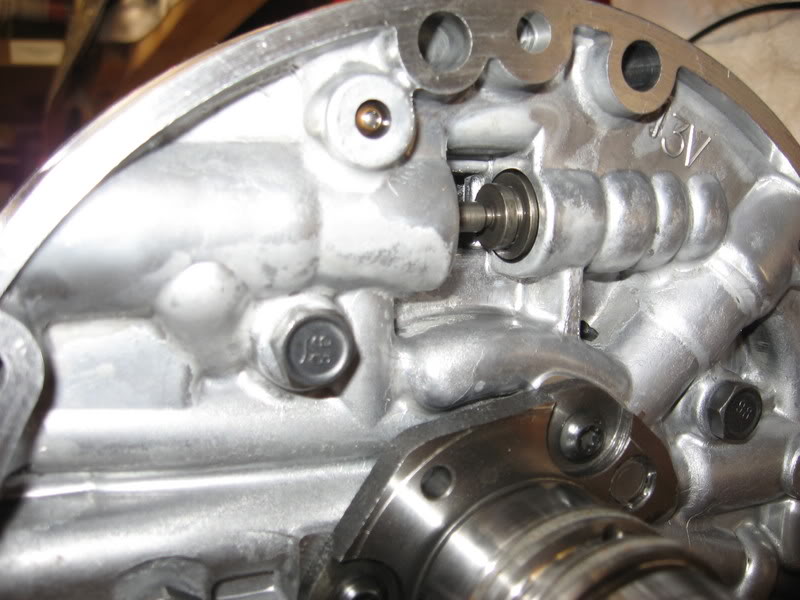
Once the case is Jet washed and rinsed thoroughly, you can start with a small aggressive file to remove "flashing" from the case in the passages and openings everywhere. If any bolt holes need to be repaired, do it now. Next with a large flat non aggressive file, do the valve body area all the way out to the pan gasket area. You want to remove high spots. Do the same to the fornt of the case where it mates with the engine block, and the area at the back of the case where the tail housing connects. Again, you want to remove high spots. Take 400 grit sand paper (go easy when sanding) and sand the area where the front pump o-ring contacts the case, go around not front to back when sanding. Do this where the low/reverse piston sits in the case, again, go around not front to back when sanding, and do the 2-4 servo area, again, you want to remove high spots, this will make sure the seals do not cut themselves on installation. If you find powdered metal in the 2-4 servo area, you will need to clean it with some solvent. Take a small flat non aggressive file to the front pump gasket area, and make sure that it is flat, no high spots. Remove checkball in the capsule over the low/reverse apply feed holes in the rear of the case, leave the capsule just remove the checkball. This makes for a better reverse engagement. Make sure the 3rd accumulator checkball capsule is in good shape (no rust), and there is no debris in it. It sits behind the 2-4 band apply servo. Remove & install the new selector shaft seal. Install the rear bronze case bushing with the flat area where the tangs come together toward the bottom of the case. Use air to blow everything clean. Wear safety glasses when doing this. Case is now ready to start parts installation.
Last edited by PBA; 02-13-2007 at 07:55 AM.
02-13-2007, 11:40 AM
#26

For better working conditions I'd get an engine stand, you can mount the trans bellhousing up using the three tabs on top of the case. Or a bench with a 3" hole drilled in it. The bench with a hole also works well for holding the input, and pump while working on them. I have a bench with two holes. One for standing the trans up in and one for working the pump, input and whatever else.
And if you get a shift kit like the transgo 4L60E HD2-B or any of their kits that have the stronger 3-4 and forward springs you're going to NEED a spring depressor to put that clip back on. Plus you won't need the helper springs especially if you use more frictions in the 3-4 clutch, they will be too short.
And if you get a shift kit like the transgo 4L60E HD2-B or any of their kits that have the stronger 3-4 and forward springs you're going to NEED a spring depressor to put that clip back on. Plus you won't need the helper springs especially if you use more frictions in the 3-4 clutch, they will be too short.
02-13-2007, 12:48 PM
#27
Launching!
Thread Starter
iTrader: (2)
Join Date: May 2005
Location: Rochester Mn
Posts: 285
Likes: 0
Received 0 Likes
on
0 Posts
8a8mfh,
I plan on drilling a couple holes in my bench when I put the input back together, I'd also like to get one of those fixture supports so I could just rotate the trans about it's axis from my bench. Money and time... we'll see.
I hear you on the spring compressor, I'm going to look into getting one (maybe a rental) when it comes time to put those parts back in.
I've ordered my kit now and should have it for next weekend. I went with Dana at probuilt, he was very helpful (that's all the name dropping I'll do).
I took some pictures of the hard parts to get a better idea of the type of prep work I have ahead of me.
here we go...
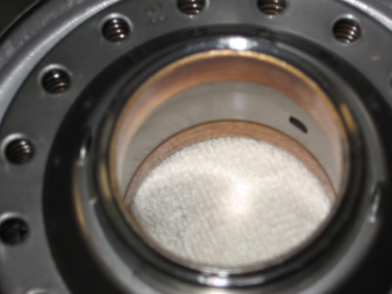
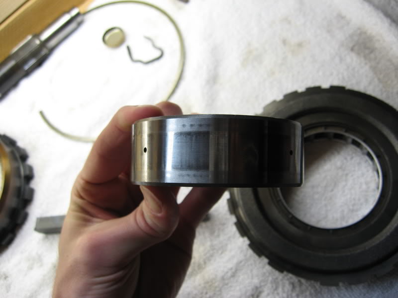
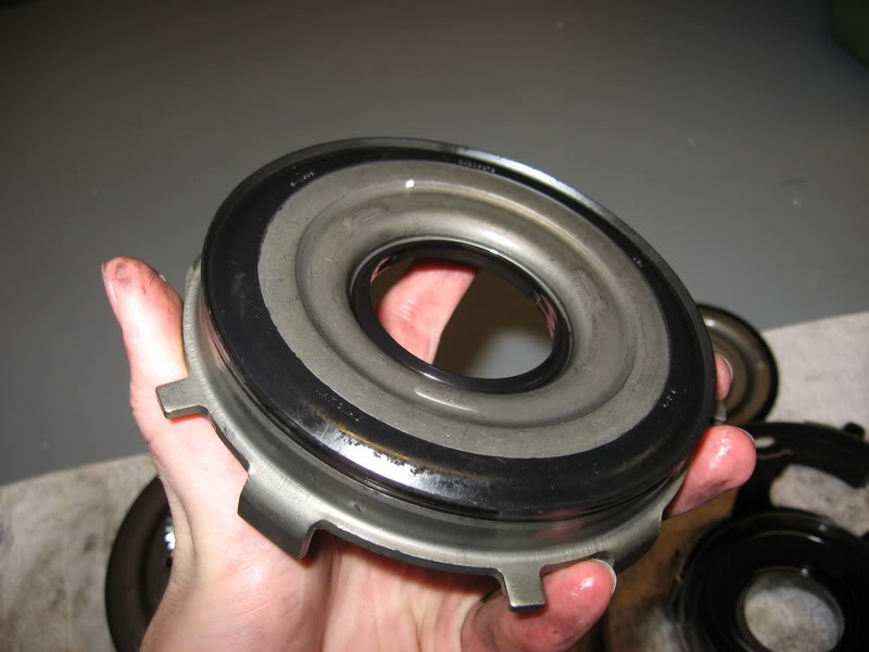
This is a shot of the inside surface of the low roller clutch - nice and smooth
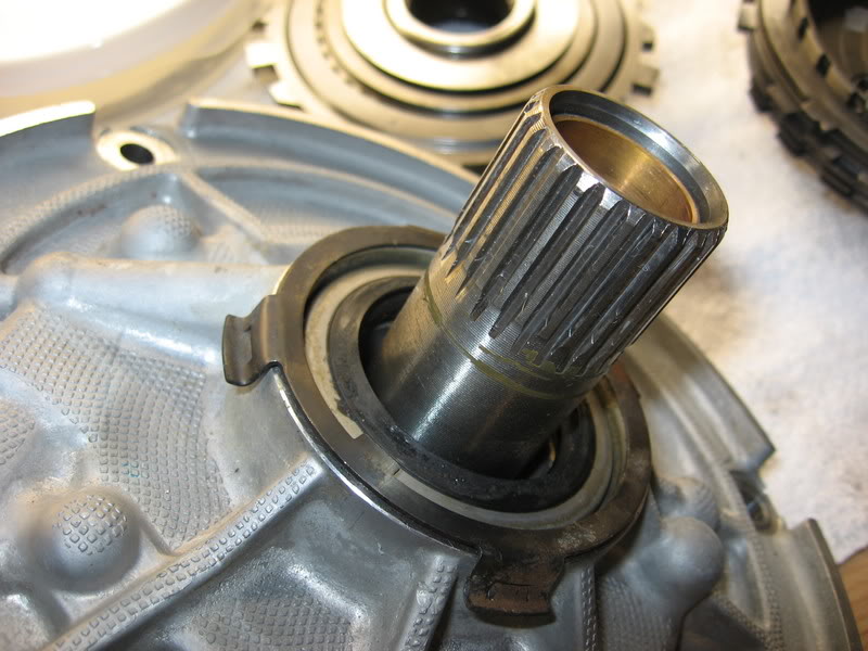
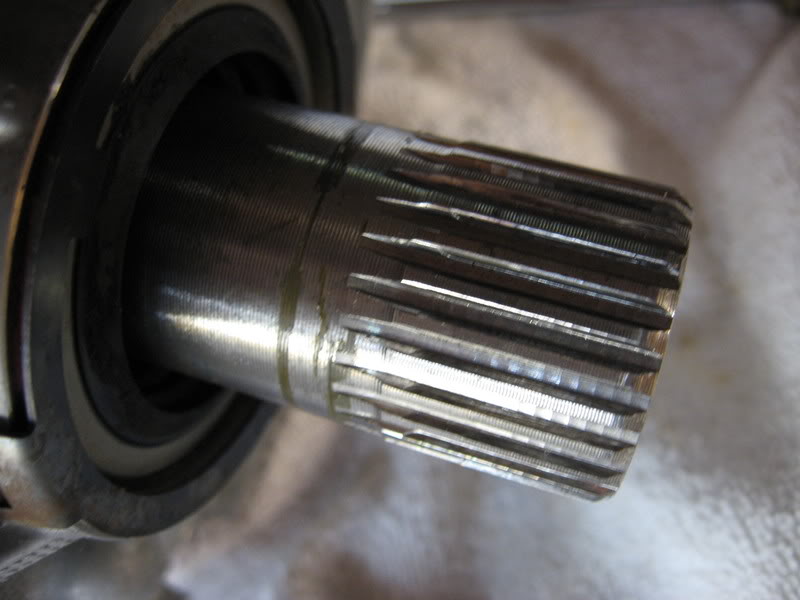
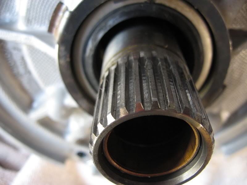
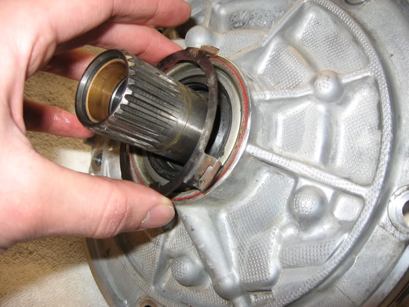
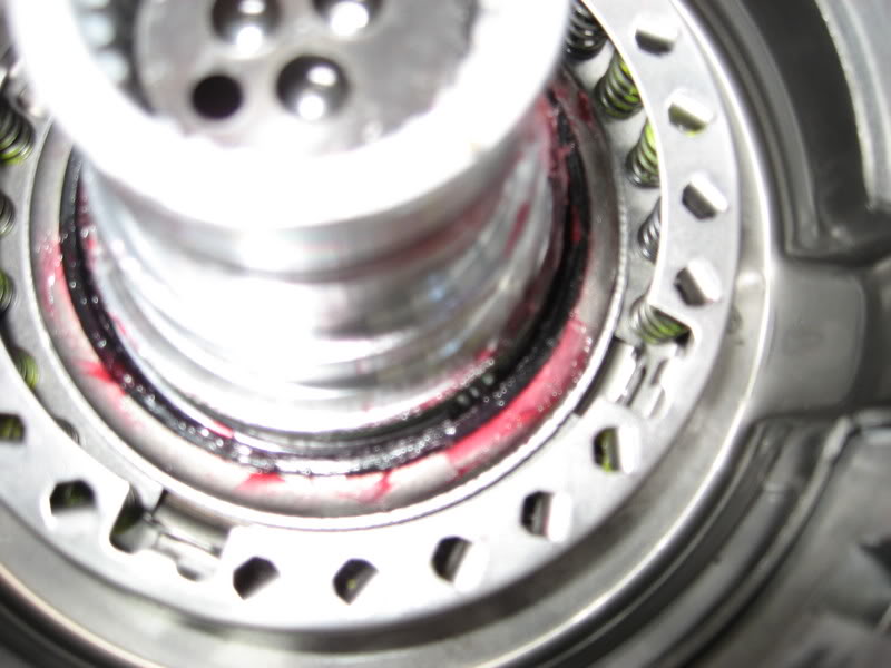
next I took the pump halves apart to check for galling in the pump. First though, there are a few shots of the stator splines to show thier condition. These have a tendency to wear. We'll see if the boss thinks I need a new one...
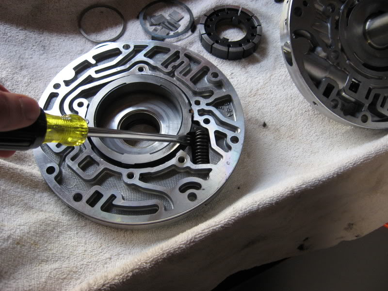
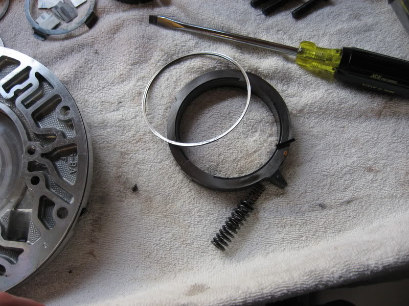
Next is the seal retainer ring, I just pulled it off by hand - a screwdriver would also work nicely.
Here is the stator half - all cleaned up
This is the pump half - I put some of the 13 veins back in for demonstation purpose, but it's clear how it works.
Using a nice large flat blade, you can pry the slide springs up and pull the slide. Then everthing comes out
The inside of the pump should be smooth, not worn. Mine had an ever so slight grove in it that I could feel if I pressed hard with my finger nail. We'll see what the boss says...
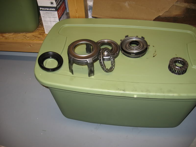
Moving right along. Next I took the input sprag assembly apart to check it's health. There's a caged assembly inside after you pop the snap ring.
The inner race should be a mirror finish and the outer race should be rougher. First shot is the inner, second is the outer.
Because my forward clutches were toast, it was reccomended that I check my forward piston for lip seal damage or cracking. I didn't see any - but my eyes arent exactly trained
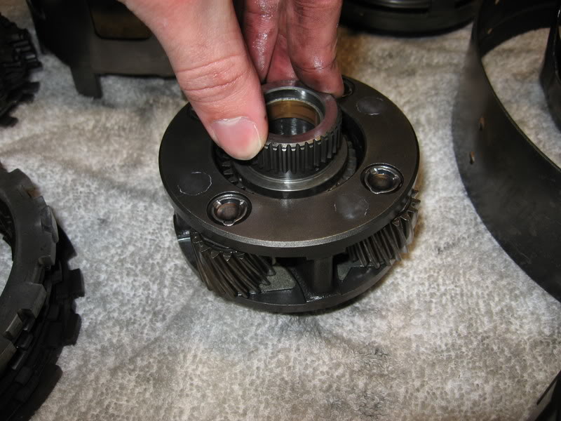
miscellaneous shot - checking the planetary for wear. Push the sun gear and twist. I should be smooth and free.
Enjoy,
Nick
I plan on drilling a couple holes in my bench when I put the input back together, I'd also like to get one of those fixture supports so I could just rotate the trans about it's axis from my bench. Money and time... we'll see.
I hear you on the spring compressor, I'm going to look into getting one (maybe a rental) when it comes time to put those parts back in.
I've ordered my kit now and should have it for next weekend. I went with Dana at probuilt, he was very helpful (that's all the name dropping I'll do).
I took some pictures of the hard parts to get a better idea of the type of prep work I have ahead of me.
here we go...
This is a shot of the inside surface of the low roller clutch - nice and smooth
next I took the pump halves apart to check for galling in the pump. First though, there are a few shots of the stator splines to show thier condition. These have a tendency to wear. We'll see if the boss thinks I need a new one...
Next is the seal retainer ring, I just pulled it off by hand - a screwdriver would also work nicely.
Here is the stator half - all cleaned up
This is the pump half - I put some of the 13 veins back in for demonstation purpose, but it's clear how it works.
Using a nice large flat blade, you can pry the slide springs up and pull the slide. Then everthing comes out
The inside of the pump should be smooth, not worn. Mine had an ever so slight grove in it that I could feel if I pressed hard with my finger nail. We'll see what the boss says...
Moving right along. Next I took the input sprag assembly apart to check it's health. There's a caged assembly inside after you pop the snap ring.
The inner race should be a mirror finish and the outer race should be rougher. First shot is the inner, second is the outer.
Because my forward clutches were toast, it was reccomended that I check my forward piston for lip seal damage or cracking. I didn't see any - but my eyes arent exactly trained
miscellaneous shot - checking the planetary for wear. Push the sun gear and twist. I should be smooth and free.
Enjoy,
Nick
02-18-2007, 08:33 AM
#28
The low/reverse inner rece looks good. Stator support teeth are in fair shape, not bad. The pump looks good, with very little wear. Take a file to both halves for high spots. The input sprag looks like it wore well. The inner race (hard to tell from the picture) looks nice & smooth (which it should be) the outer race looks like it wore well, just use 36 grit (outer race only) going around, not front to back to roughen it up. The reverse input clutches wore perfectly. The area where the 2-4 band rides on the reverse input drum is bad, you will need to replace the drum. Make sure that the next drum (new or used) is perfectly flat where the drum rides. Even a lot of the new GM or aftermarket drums are not flat, so check for this, otherwise you will be back into the unit very soon.
02-28-2007, 04:21 PM
#29
Launching!
Thread Starter
iTrader: (2)
Join Date: May 2005
Location: Rochester Mn
Posts: 285
Likes: 0
Received 0 Likes
on
0 Posts
I'm glad you're amused Todd.
I'll see what I can do about video.
The teflon seals in my kit do not need to be sized according to Dana, they interlock.
I will be going through the valve body and installing the transgo kit.
I have a beast shell.
I also have a lip seal installer.
If you have a way to check planetarys that you feel I should know, I'd appreciate it if you added it to the thread.
Maybe next I'll do a thread on R&R for your enjoyment.
Nick
Originally Posted by WE TODD DID
This thread is hilarious! Wait till you try to put the pistons back in the drums with the roll of masking tape! Be sure to get some video of that, rather than pictures! Also, what are you going to do about ring sizers, or updating the valve body? What about an updated shell? Do you have a lip seal installer? How about the rear planet which are notorious for coming apart? Do you know how to check for worn planets? You definitely picked a hell of a transmission to try for your first time! Hopefully you have some good experience R&Ring it because I have a feeling that you're gonna have it out a few times! Btw, a cheap version of a piston compressor is about $100
03-01-2007, 06:51 PM
#30
Originally Posted by VORTECFCAR
I'm glad you're amused Todd.
I'll see what I can do about video.
The teflon seals in my kit do not need to be sized according to Dana, they interlock.
I will be going through the valve body and installing the transgo kit.
I have a beast shell.
I also have a lip seal installer.
If you have a way to check planetarys that you feel I should know, I'd appreciate it if you added it to the thread.
Maybe next I'll do a thread on R&R for your enjoyment.
Nick
I'll see what I can do about video.
The teflon seals in my kit do not need to be sized according to Dana, they interlock.
I will be going through the valve body and installing the transgo kit.
I have a beast shell.
I also have a lip seal installer.
If you have a way to check planetarys that you feel I should know, I'd appreciate it if you added it to the thread.
Maybe next I'll do a thread on R&R for your enjoyment.
Nick
03-10-2007, 08:55 AM
#32
Launching!
Thread Starter
iTrader: (2)
Join Date: May 2005
Location: Rochester Mn
Posts: 285
Likes: 0
Received 0 Likes
on
0 Posts
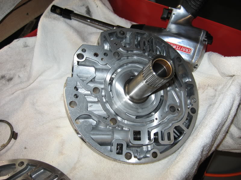
I've been tinkering again guys, here are some pics of pump reassembly and assorted stuff. I have most of this weekend free so I plan to get quite a bit done. This is just to wet the appetite.
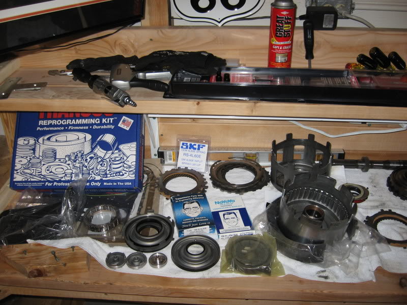
Heres a complehensive shot of my rebuild kit. There's quite a bit of stuff here! clutches, steels, seals, pump, pistons, sprags, and input drum to name a few
My first order of business was putting the pump back together. I got a new slide and all the pump goodies. Heres a shot of the slide oring being put together before it goes back into the pump
Before reassembly I made sure the slide sits with .001-.002 clearance dry to the pump half. Then I put down some trans gel, put the green swiper and pivot pin in.
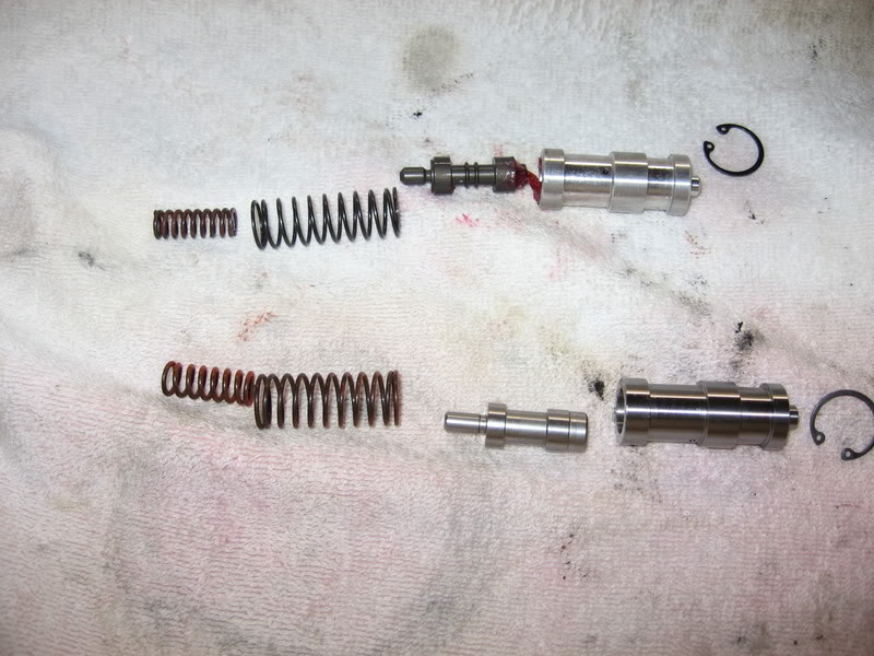
This is a shot of took to compare the new spring in the pump to the old spring I took out. The new spring is a pretty tough egg. I had to get creative to get it into place.
Heres a shot of the new pump going in. Theres a plastic piece the gets some trans gel and goes down. Be sure and place the new ring on the bottom to support the veins (see next shot).
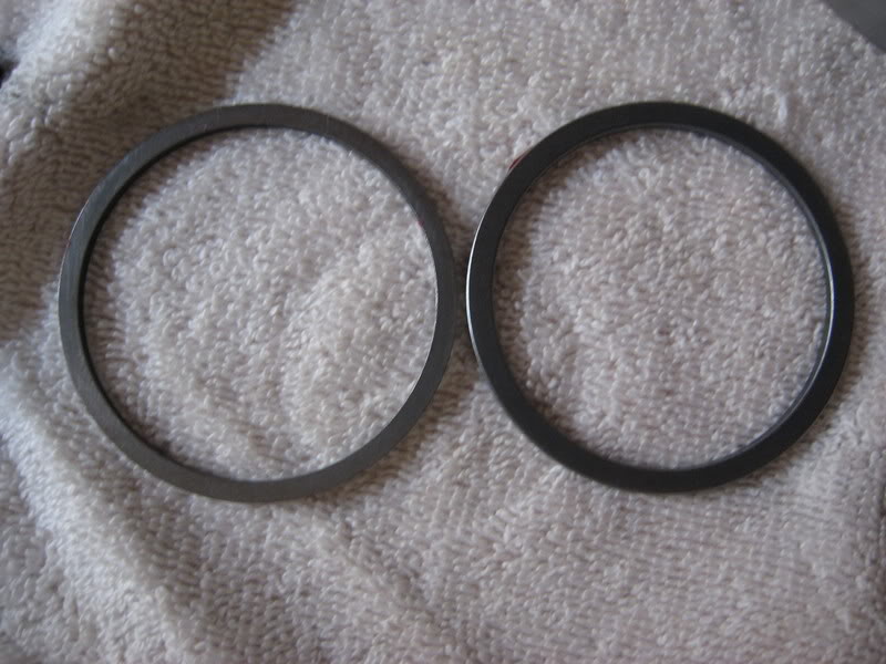
This is just a quick comparo shot I took of the new hardened ring vs. the stocker. Supposidly the stock has a tendency to break.
Heres the pump with the veins back in and me spinning it to make sure it moves freely. I put some trans fluid on it for good measure. My fingers are where the two fingers of the torque converter will grab.
This is just a completed shot of the pump half.
Heres a complehensive shot of my rebuild kit. There's quite a bit of stuff here! clutches, steels, seals, pump, pistons, sprags, and input drum to name a few
My first order of business was putting the pump back together. I got a new slide and all the pump goodies. Heres a shot of the slide oring being put together before it goes back into the pump
Before reassembly I made sure the slide sits with .001-.002 clearance dry to the pump half. Then I put down some trans gel, put the green swiper and pivot pin in.
This is a shot of took to compare the new spring in the pump to the old spring I took out. The new spring is a pretty tough egg. I had to get creative to get it into place.
Heres a shot of the new pump going in. Theres a plastic piece the gets some trans gel and goes down. Be sure and place the new ring on the bottom to support the veins (see next shot).
This is just a quick comparo shot I took of the new hardened ring vs. the stocker. Supposidly the stock has a tendency to break.
Heres the pump with the veins back in and me spinning it to make sure it moves freely. I put some trans fluid on it for good measure. My fingers are where the two fingers of the torque converter will grab.
This is just a completed shot of the pump half.
03-10-2007, 09:12 AM
#33
Launching!
Thread Starter
iTrader: (2)
Join Date: May 2005
Location: Rochester Mn
Posts: 285
Likes: 0
Received 0 Likes
on
0 Posts
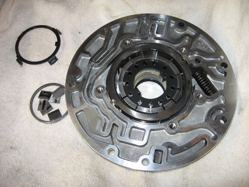
This next series will be valve inspection, filter replacement, and seal replacement.
The first one here is of the seal that holds the trans filter. This thing is a little tricky. Take my advice and use a half inch pipe threaded into the seal with a 90 degree bend on one end. Whack the 90 with a hammer and the seal should come right out. Here's a shot of what you can try if you don't have a 90 and pipe (stator half of the pump).
Here's the first valve lineup I took out. I had some help from buddy Chucky so I was able to get some two handed shots
You can check these by putting them in their respective bores without the springs and then looking down the bore to see how much light is around the valves. Also notice what a good pump holder your new beast sunshell makes.
The next few shots will just be of the various valve lineups. This should give you an idea of what it's like to take the pump apart completely. These valves go in many different ways without a fuss, so watch what you're doing!
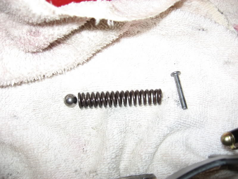
THERE's ONLY ONE RIGHT WAY.
captured spring and ball. Pull the pin and be careful.
Stay Tuned!
The first one here is of the seal that holds the trans filter. This thing is a little tricky. Take my advice and use a half inch pipe threaded into the seal with a 90 degree bend on one end. Whack the 90 with a hammer and the seal should come right out. Here's a shot of what you can try if you don't have a 90 and pipe (stator half of the pump).
Here's the first valve lineup I took out. I had some help from buddy Chucky so I was able to get some two handed shots
You can check these by putting them in their respective bores without the springs and then looking down the bore to see how much light is around the valves. Also notice what a good pump holder your new beast sunshell makes.
The next few shots will just be of the various valve lineups. This should give you an idea of what it's like to take the pump apart completely. These valves go in many different ways without a fuss, so watch what you're doing!
THERE's ONLY ONE RIGHT WAY.
captured spring and ball. Pull the pin and be careful.
Stay Tuned!
03-10-2007, 09:17 AM
#34
You might not want to use that skf input sprag. We have seen many failures with that style. Also I was looking at the new priming spring that you installed into the pump. You might want to double check if you should still be using the factory inner spring. I believe that you were supposed to discard it.
03-10-2007, 01:19 PM
#35
Launching!
Thread Starter
iTrader: (2)
Join Date: May 2005
Location: Rochester Mn
Posts: 285
Likes: 0
Received 0 Likes
on
0 Posts
I gave Vince a call to clear a few things up. Very helpful guy...
The springs I had placed in pump slide position were 1 too many. Only use the one big spring. Do not reuse the inner spring.
I started putting my sprag back together shortly before reading this. I took it apart and am going to wait for a double cage setup from borg warner. Better safe than r&r'd again. I didn't really get as far as I would have liked to today, I had trouble with the spring cage after I put the transgo springs in it. Pictures show what happened (pretty much the cage **** the bed).
I start out here with the pics of the new pressure relief setup I installed in the pump.
Next, with the pump back together (again) I used a small flat balde to make sure the rotor still spins freely. wow...it works.
New thrust washer and seals on the pump.
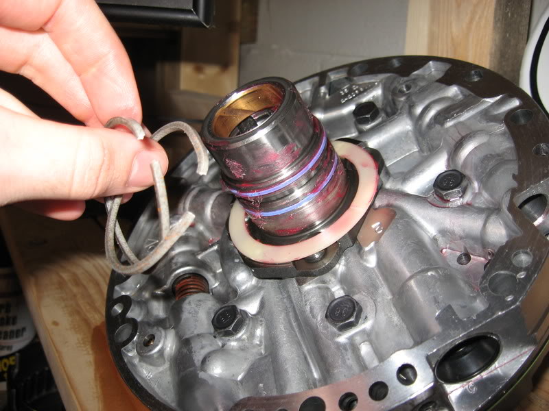
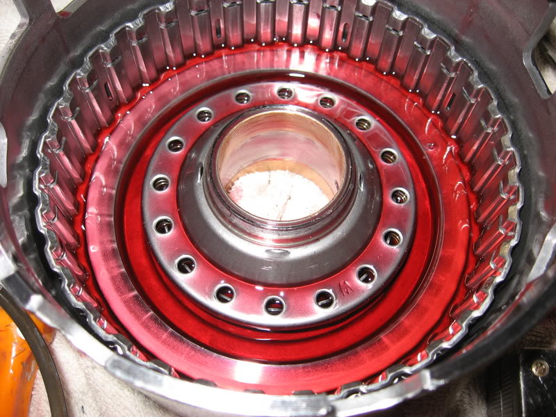
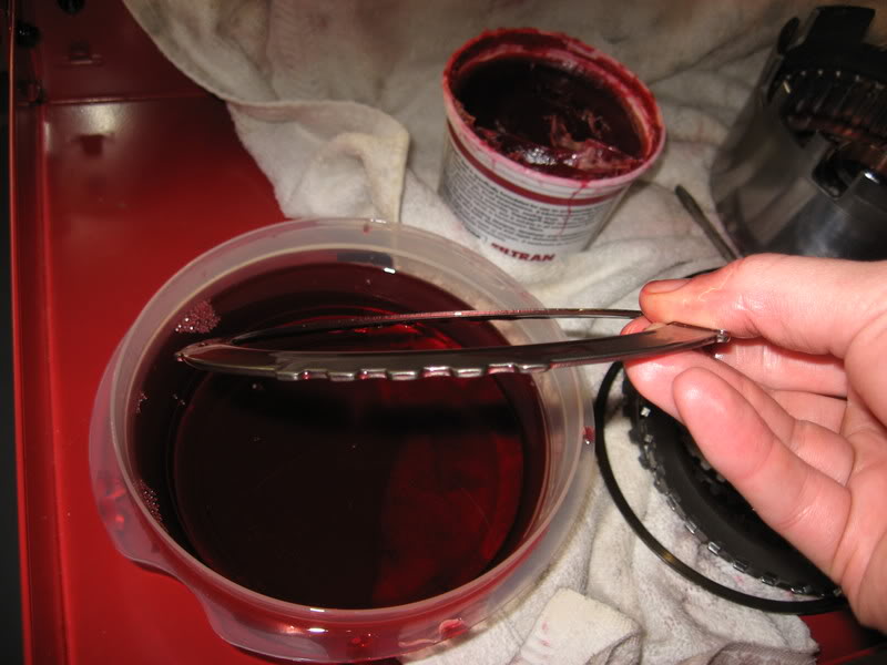
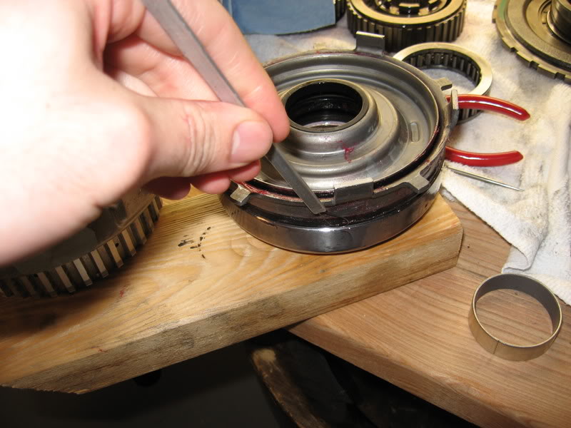
On to the low reverse drum. I bought a new drum because my old one had some wear from the band on it. I had to transfer all of the innards to the new drum. First, put a bunch of trans gel on the inside where the seals go and then put the new lip seals on the apply piston. Here it is before it goes in.
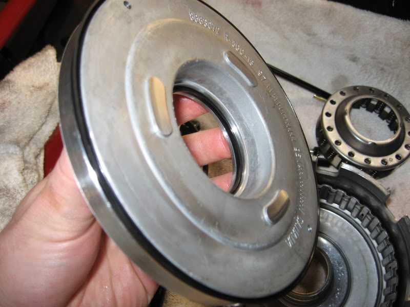
Put it in the drum and chase the seals with this clever tool. This thing takes some getting used to, so chill or risk ruining your new seals. Lip faces down.
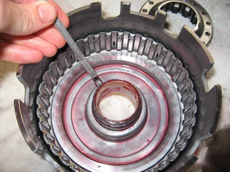
Use a little magic to get your snap ring in after putting the piston return spring cage deal back in.
this is the first steel that goes in, it has a weird sprung shape so keep track of it. Then load the clutches and steels in and finish with a snap ring. I was slacking on pictures for the rest of the drum assembly. It goes pretty easy.
Here's a shot of my input holder. I should have been a carpenter.
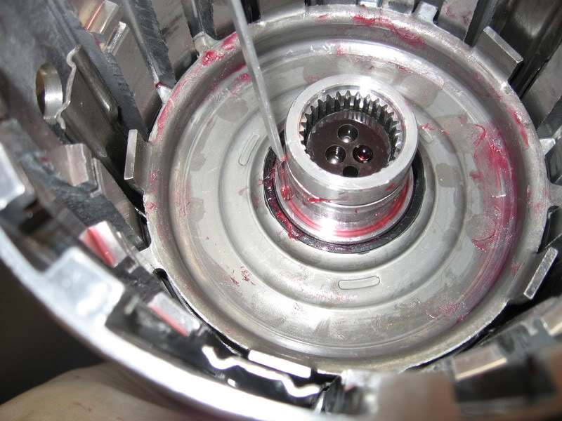
green oring goes in first
then the piston, be liberal with the lube. Chase the outer seal on this one. If you're having trouble chasing seals - pretend you're a hungry Eskimo...
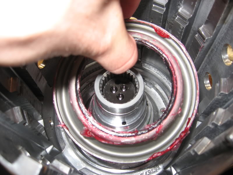
In ya go
...and here's where I start to get pissed. The new transgo springs are supposed to go in the cage next and sit on the clutch fork. Annoying...22 of the little yellow ******.

Heres what happens when you try to put the cage back together. Have a magnet ready for when the tangs break and springs go everywhere.
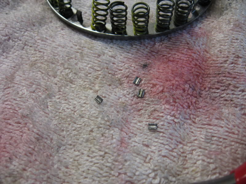
Sorry about the slow progress, but looks like I have to order more crap.
The springs I had placed in pump slide position were 1 too many. Only use the one big spring. Do not reuse the inner spring.
I started putting my sprag back together shortly before reading this. I took it apart and am going to wait for a double cage setup from borg warner. Better safe than r&r'd again. I didn't really get as far as I would have liked to today, I had trouble with the spring cage after I put the transgo springs in it. Pictures show what happened (pretty much the cage **** the bed).
I start out here with the pics of the new pressure relief setup I installed in the pump.
Next, with the pump back together (again) I used a small flat balde to make sure the rotor still spins freely. wow...it works.
New thrust washer and seals on the pump.
On to the low reverse drum. I bought a new drum because my old one had some wear from the band on it. I had to transfer all of the innards to the new drum. First, put a bunch of trans gel on the inside where the seals go and then put the new lip seals on the apply piston. Here it is before it goes in.
Put it in the drum and chase the seals with this clever tool. This thing takes some getting used to, so chill or risk ruining your new seals. Lip faces down.
Use a little magic to get your snap ring in after putting the piston return spring cage deal back in.
this is the first steel that goes in, it has a weird sprung shape so keep track of it. Then load the clutches and steels in and finish with a snap ring. I was slacking on pictures for the rest of the drum assembly. It goes pretty easy.
Here's a shot of my input holder. I should have been a carpenter.
green oring goes in first
then the piston, be liberal with the lube. Chase the outer seal on this one. If you're having trouble chasing seals - pretend you're a hungry Eskimo...
In ya go
...and here's where I start to get pissed. The new transgo springs are supposed to go in the cage next and sit on the clutch fork. Annoying...22 of the little yellow ******.
Heres what happens when you try to put the cage back together. Have a magnet ready for when the tangs break and springs go everywhere.
Sorry about the slow progress, but looks like I have to order more crap.
03-10-2007, 06:34 PM
#36
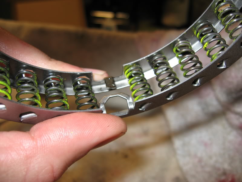
The tangs on that spring cage are no longer being used. Just so you know. I usually bend them in opposite ways of each other so that they do not interfere with one another. I have seen many builders do many different things with those tangs. Looks like you having fun. Vince
 03-14-2007, 08:02 AM
#38
Launching!
Thread Starter
iTrader: (2)
Join Date: May 2005
Location: Rochester Mn
Posts: 285
Likes: 0
Received 0 Likes
on
0 Posts
Thanks again for the encouragement guys, look for some more pics up today.
The sprag was purchased from bulkpart. They have really good prices and everything is internet cataloged.
Where did you order the borg warner sprag from.
Last edited by Ragtop 99; 11-23-2007 at 01:33 PM.
03-16-2007, 06:43 PM
#39
Launching!
Thread Starter
iTrader: (2)
Join Date: May 2005
Location: Rochester Mn
Posts: 285
Likes: 0
Received 0 Likes
on
0 Posts
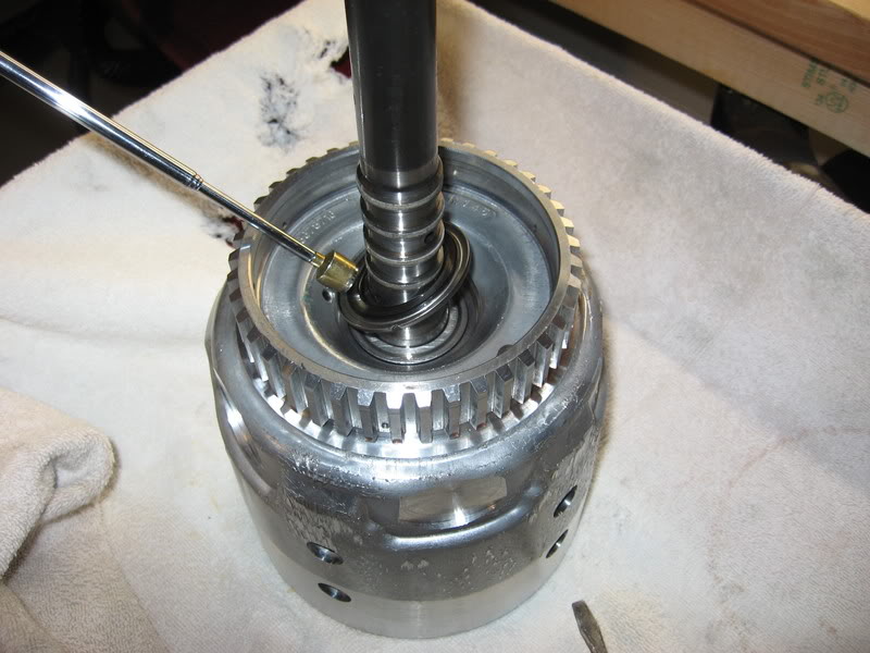
Got my press today fellas, had a little time to put the input drum back together.
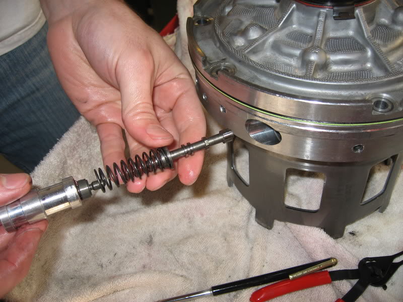
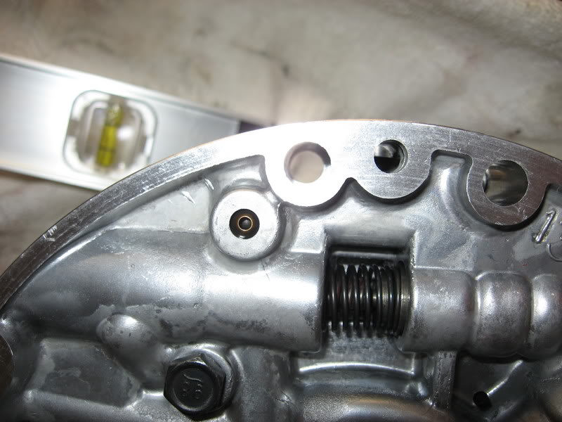
Here's a shot of my modified return spring cage. Just clip the retainer tangs off and carefully set the cage with springs onto the apply piston. You'll probably be pretty good at catching springs and cursing by this time.
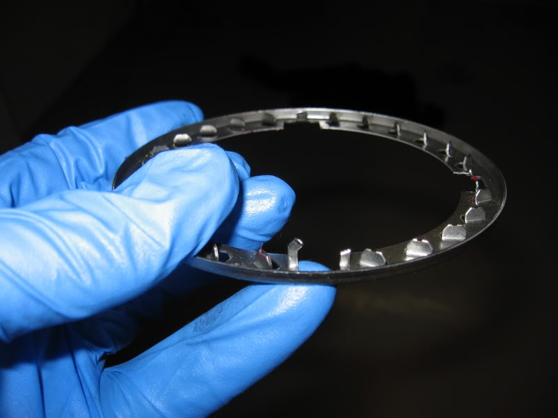
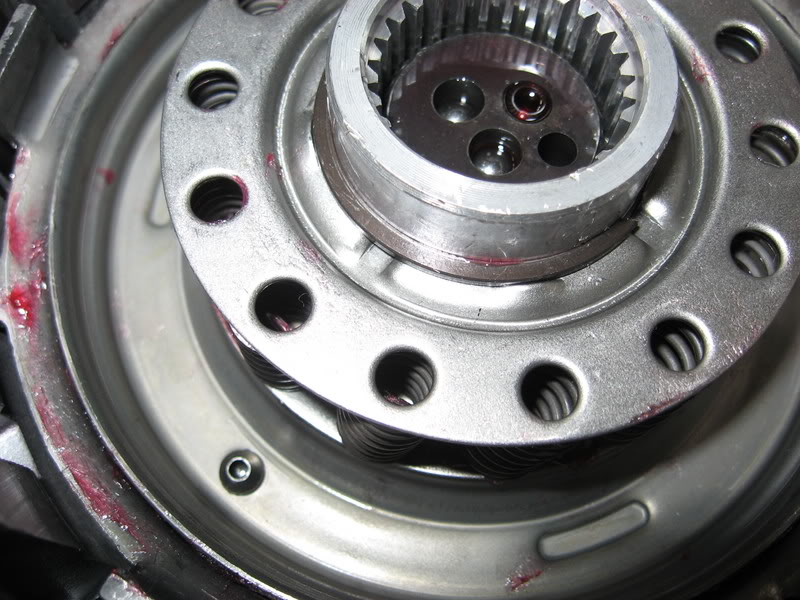
Heres a shot of the springs in the drum without the top of the cage.
...and then again with the top of the cage on. This is for demonstration purposes only. Install as a complete unit!
One of the pistons needs to by put in its carrier before entering the case. It's the bottom two in this picture. The top piston in this pic gets put in after you've chased the seals on the bottom two and seated them.
Heres a shot of my chasing the inner seal on the top piston.
It's down all the way when you can feel the spring pack push back on it. This will be hard with those tight springs, but you can feel/see it.
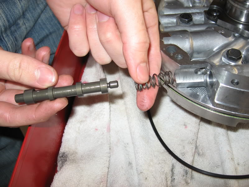
Next is another spring pack. This one also gets loaded with some tough springs. It's very important that these springs all be properly seated or you could have a hard time getting the snap ring on - or catastrophic transmission failure (I just wanted to say that).
Here's a shot of my modified return spring cage. Just clip the retainer tangs off and carefully set the cage with springs onto the apply piston. You'll probably be pretty good at catching springs and cursing by this time.
Heres a shot of the springs in the drum without the top of the cage.
...and then again with the top of the cage on. This is for demonstration purposes only. Install as a complete unit!
One of the pistons needs to by put in its carrier before entering the case. It's the bottom two in this picture. The top piston in this pic gets put in after you've chased the seals on the bottom two and seated them.
Heres a shot of my chasing the inner seal on the top piston.
It's down all the way when you can feel the spring pack push back on it. This will be hard with those tight springs, but you can feel/see it.
Next is another spring pack. This one also gets loaded with some tough springs. It's very important that these springs all be properly seated or you could have a hard time getting the snap ring on - or catastrophic transmission failure (I just wanted to say that).
03-16-2007, 07:20 PM
#40
Launching!
Thread Starter
iTrader: (2)
Join Date: May 2005
Location: Rochester Mn
Posts: 285
Likes: 0
Received 0 Likes
on
0 Posts
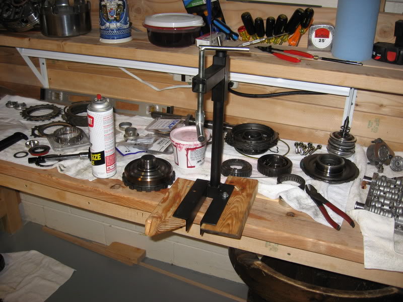
Check out my new Tool. Now I'm a professional. 
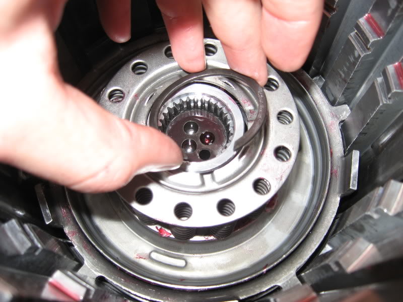
set the thick installation washer on top of the spring cage and lower the feet on the press to get the snap ring in.
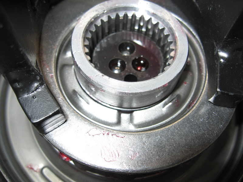
There are little slots on top of the cage to 'contain' the snap ring. I had to use some gently screwdrive pressure to everything in its place.
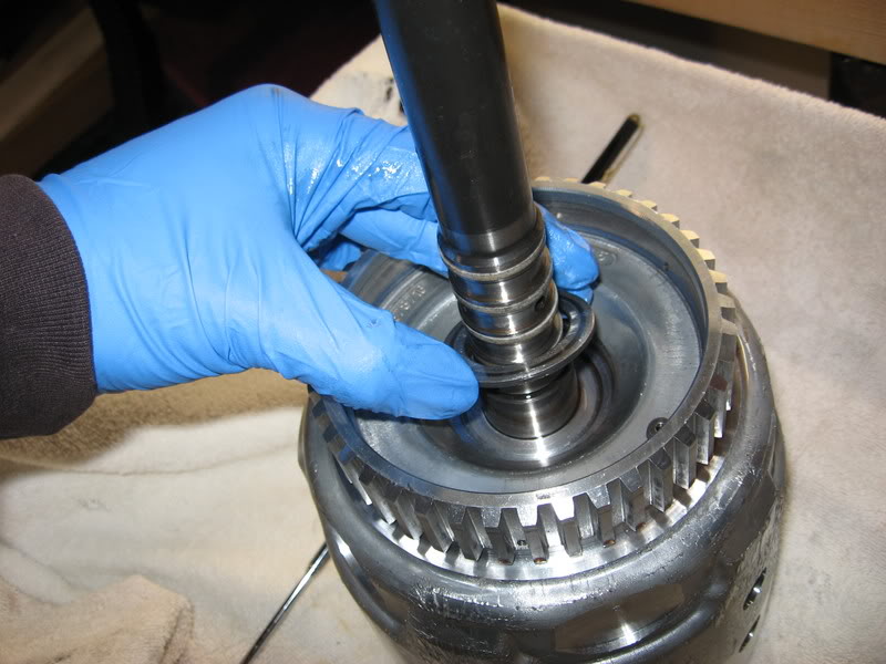
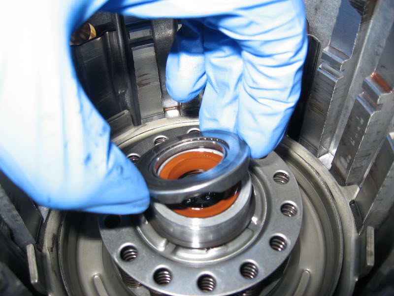
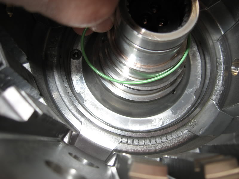
Put some lube on the top of the shaft and put your new seal and torrington bearing on. The seal goes in easy enough and should sit flat. I was liberal with my transgel as you'll see in the second shot.
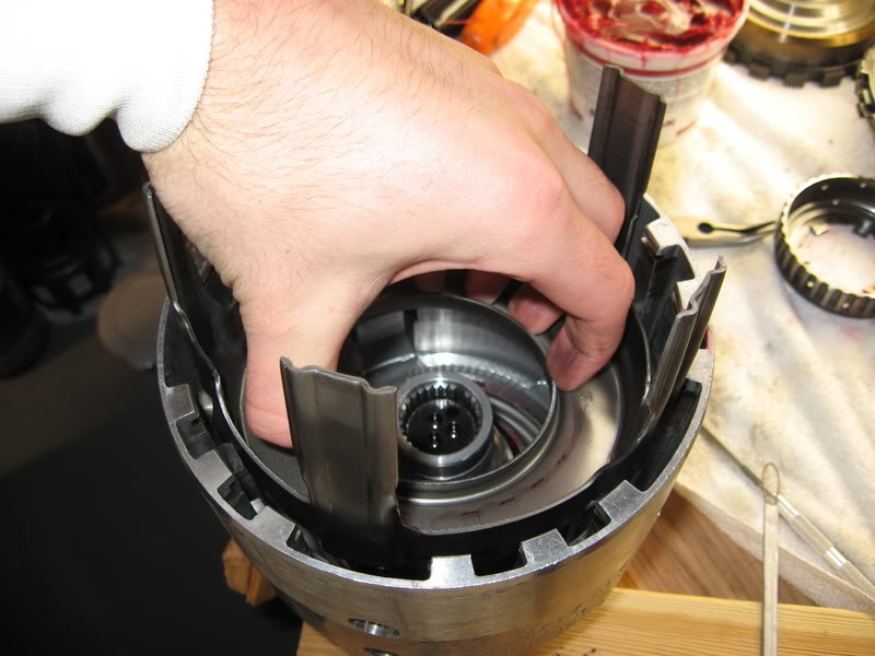
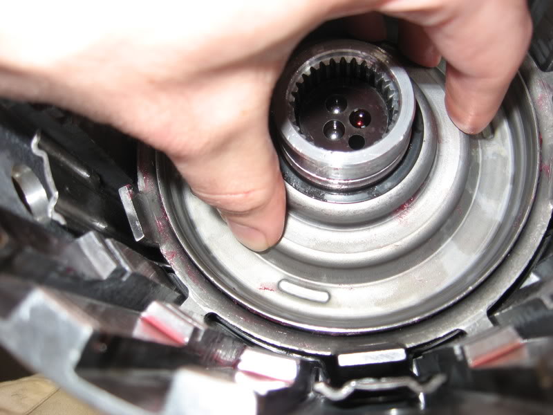
Now you can throw your overrun clutches in to presoak in some trans fluid while you put the input sprag together.
Heres a shot of the difference between an SKF sprag and the Borg Warner unit. There are folks on both sides of the fence on this one. I like the looks of the borg warner myself. I'll keep the SKF for my daily driver build.
Putting this thing together can be a real test of patience. Take your time and twist counter clockwise - put the sprag in the outer race first and insert the inner piece. It will go eventually. You'll know you did it right when it turns smoothly one way and locks hard the other.
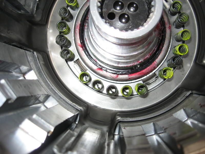
After you put the overrun clutches in, put the sprag in. Twist untill all clutches are engaged and the sprag rides on the torrington bearing. Then put your pressure plate.
Next into the case is the wavey steel, then another steel and the forward clutch pack. I had to reuse my forward clutch pressure plate. I just took some super fine sand paper and rubbed until it looked new

Put the forward clutches and steels in followed by the cleaned up pressure plate, then put your snap ring on. You may have several laying around by this time. Use the right one! I prefer the two screwdrive method.
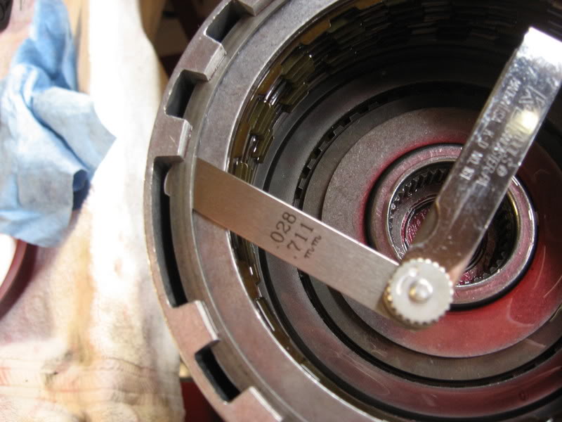
Check you clearance on the pack. I believe mine was about .050.
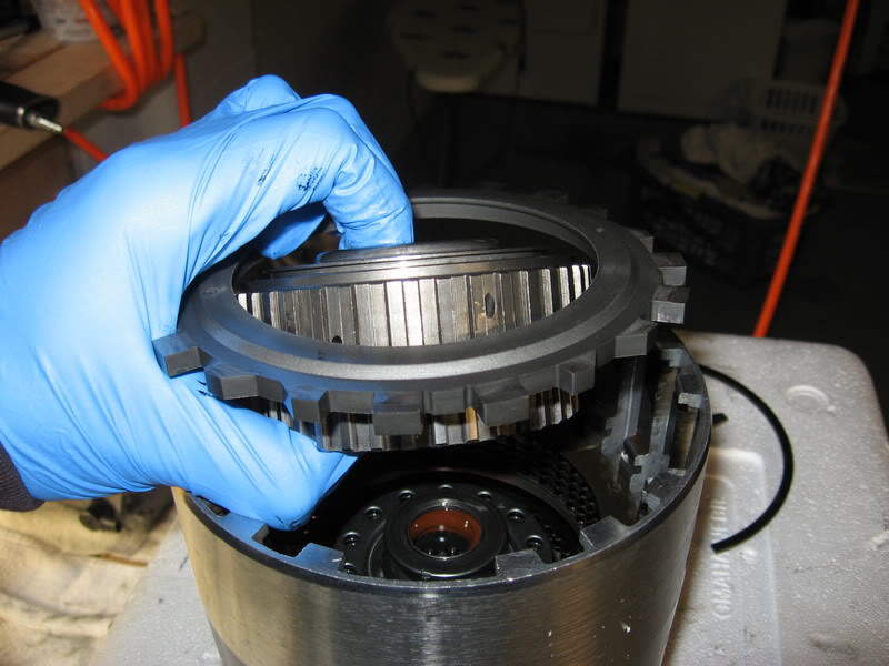
Heres the next pressure plate you'll be installing. This is for the 3-4 clutch pack. This is kind of a hybrid setup so you can use more clutches and steels (8).
Soak and install the 3-4 clutches
Put your new snap ring on and check clearance again. This is the one I'm not so sure about. It says I should have about double this clearance. I'd appreciate if someone would chime in on this...? Whats safe?
Thanks guys,
Nick
set the thick installation washer on top of the spring cage and lower the feet on the press to get the snap ring in.
There are little slots on top of the cage to 'contain' the snap ring. I had to use some gently screwdrive pressure to everything in its place.
Put some lube on the top of the shaft and put your new seal and torrington bearing on. The seal goes in easy enough and should sit flat. I was liberal with my transgel as you'll see in the second shot.
Now you can throw your overrun clutches in to presoak in some trans fluid while you put the input sprag together.
Heres a shot of the difference between an SKF sprag and the Borg Warner unit. There are folks on both sides of the fence on this one. I like the looks of the borg warner myself. I'll keep the SKF for my daily driver build.
Putting this thing together can be a real test of patience. Take your time and twist counter clockwise - put the sprag in the outer race first and insert the inner piece. It will go eventually. You'll know you did it right when it turns smoothly one way and locks hard the other.
After you put the overrun clutches in, put the sprag in. Twist untill all clutches are engaged and the sprag rides on the torrington bearing. Then put your pressure plate.
Next into the case is the wavey steel, then another steel and the forward clutch pack. I had to reuse my forward clutch pressure plate. I just took some super fine sand paper and rubbed until it looked new
Put the forward clutches and steels in followed by the cleaned up pressure plate, then put your snap ring on. You may have several laying around by this time. Use the right one! I prefer the two screwdrive method.
Check you clearance on the pack. I believe mine was about .050.
Heres the next pressure plate you'll be installing. This is for the 3-4 clutch pack. This is kind of a hybrid setup so you can use more clutches and steels (8).
Soak and install the 3-4 clutches
Put your new snap ring on and check clearance again. This is the one I'm not so sure about. It says I should have about double this clearance. I'd appreciate if someone would chime in on this...? Whats safe?
Thanks guys,
Nick