That just happened........

 07-30-2012, 09:33 AM
#42


I'm a little jealous of the AFRs. They are pretty. I just couldn't spend that kind of money on the small bore setup. I'll hit 100k miles this year. I know the motor won't last forever so the stage 2.5 TSP heads will hold me over until I build a new motor.
 08-01-2012, 08:46 PM
#44
So my old LS6 fuel rail has a fuel regulator on the fuel rail itself.....the LS2 fuel rail on the right does not. Am I going to have to add one? How does the stock LS2 one get regulated?
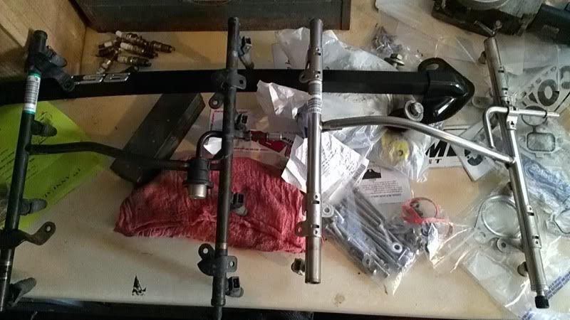
Last edited by lollygagger8; 08-01-2012 at 08:55 PM.
08-01-2012, 11:35 PM
#45
TECH Regular
iTrader: (9)
Join Date: May 2009
Location: Lake Worth,TX
Posts: 498
Likes: 0
Received 0 Likes
on
0 Posts
that is not a fuel regulator. the fuel regulator is in the tank. you don't need whatever it is.
I run nasty fuel rails and they do not have that. you will be just fine installing those LS2 rails.
I run nasty fuel rails and they do not have that. you will be just fine installing those LS2 rails.
08-14-2012, 07:19 AM
#48
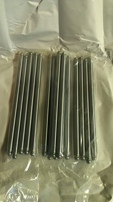
Pushrods finally came in last night......they look awesome....too bad nobody will ever see them
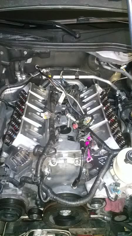
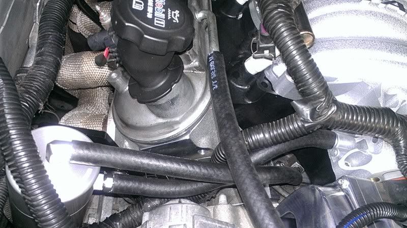
So what do I do with the Coolant Crossover tube now? Rebend to fit around the Fast 102 or cap those coolant passages off? Where does the rubber hose connect to if it's reused?
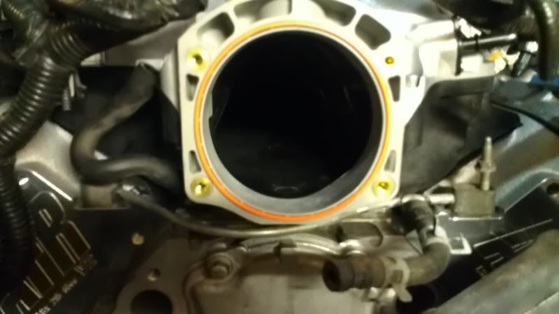
Since I don't have photoshop at work....here's the part I'm talking about:
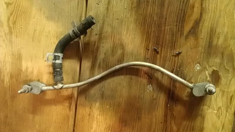
Also, does the hose from the valley cover connect to the port on the side of the Fast Intake?
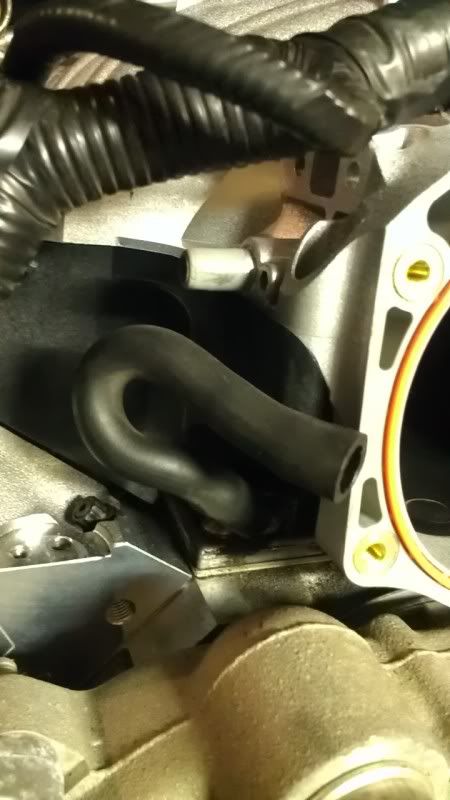
Sorry for the dumb questions!
So what do I do with the Coolant Crossover tube now? Rebend to fit around the Fast 102 or cap those coolant passages off? Where does the rubber hose connect to if it's reused?
Since I don't have photoshop at work....here's the part I'm talking about:
Also, does the hose from the valley cover connect to the port on the side of the Fast Intake?
Sorry for the dumb questions!
08-14-2012, 07:20 AM
#49
Anyways....since the UPS man didn't come until about 6pm, I decided to throw the pushrods in right then. Got the Yella Terras in, torqued, turned the motor manually and made sure they didn't hit the valve covers, (I had to freeze the new valve cover gaskets to make them fit) got valve covers on, and threw the water pump on, and connected all the stuff to the intake including fuel rail and injectors. I haven't buttoned down the Fast 102 yet, because I want to make sure everything is hooked up right. Finally getting somewhere............
08-14-2012, 09:26 AM
#50
TECH Resident
Join Date: Mar 2012
Location: Florida
Posts: 796
Likes: 0
Received 0 Likes
on
0 Posts
The valley cover vent tube connects to the side of the intake manifold, if you mix this up and connect the valve cover breather to the side of the manifold your motor will drink oil. The valve cover vent connects to the tb. Nothing worse than seeing clouds of blue smoke after you just rebuilt the top end.
08-14-2012, 10:23 AM
#53
TECH Resident
Join Date: Mar 2012
Location: Florida
Posts: 796
Likes: 0
Received 0 Likes
on
0 Posts
I'd run the catch can inline with the valve cover breather rather than the valley vent. Valve cover breather is where you will really pull oil. If you do this you can also just put a small filter on the exit of the catch can, no need to route it back into the intake if using a catch can.
Edit: the valley vent doesn't draw much oil if any, the hose on mine was petrified and broke as i pulled it off.
Edit: the valley vent doesn't draw much oil if any, the hose on mine was petrified and broke as i pulled it off.
08-15-2012, 12:24 PM
#54
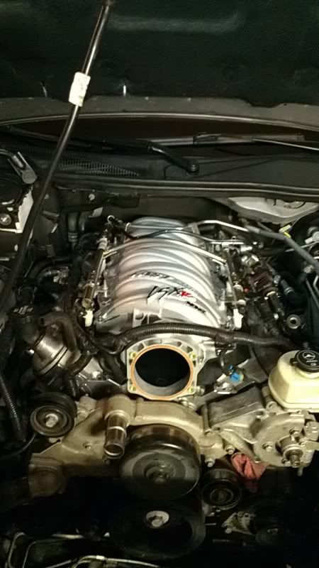
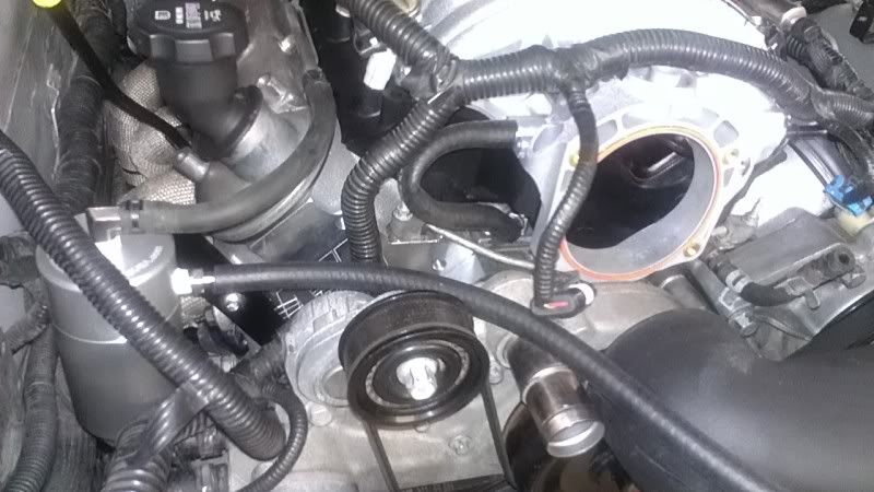
HELP!
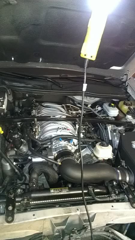
Does this look right?? The long hose will go into the air intake tube that I haven't drilled yet.
Valley Cover to Intake.
Valve cover to top of Oil Catch.
Oil Catch lower to air intake tube (not drilled yet)
I tried to copy this...
http://www.cadillacforums.com/forums...version-2.html
Does this look right?? The long hose will go into the air intake tube that I haven't drilled yet.
Valley Cover to Intake.
Valve cover to top of Oil Catch.
Oil Catch lower to air intake tube (not drilled yet)
I tried to copy this...
http://www.cadillacforums.com/forums...version-2.html
 08-15-2012, 01:57 PM
#57
TECH Resident
Join Date: Mar 2012
Location: Florida
Posts: 796
Likes: 0
Received 0 Likes
on
0 Posts
HELP!
Does this look right?? The long hose will go into the air intake tube that I haven't drilled yet.
Valley Cover to Intake.
Valve cover to top of Oil Catch.
Oil Catch lower to air intake tube (not drilled yet)
I tried to copy this...
http://www.cadillacforums.com/forums...version-2.html
Does this look right?? The long hose will go into the air intake tube that I haven't drilled yet.
Valley Cover to Intake.
Valve cover to top of Oil Catch.
Oil Catch lower to air intake tube (not drilled yet)
I tried to copy this...
http://www.cadillacforums.com/forums...version-2.html
Also this is an awesome build, curious to see what sort of numbers you get out of it.
08-15-2012, 05:29 PM
#58
This is correct, I just don't understand why you want to route the valve cover vent back to the air intake tube as stated earlier. It may be possible we are missunderstanding eachother here. The valve cover vent if connected to the catch can does not need to loop back into the system. The only reason you would do so is if you need to pass emisions and even then a catch can should suffice. With the catch can you just run the valve cover vent in, and stick a small breather filter on the out port. If you do this you shouldn't have any oil leaking out, and you don't have to drill the intake tube.
Also this is an awesome build, curious to see what sort of numbers you get out of it.
Also this is an awesome build, curious to see what sort of numbers you get out of it.
Check it out!
Waiting for tuner to come tomorrow night. I'm psyched!!!