Big 3 and AD244 Alternator Upgrade
 04-17-2013, 02:25 PM
#21
Fluid pressure does not equal voltage. Try to avoid drawing analogies between the two. The objective is higher voltage through the reduction of line impedance and by installing a newer alternator that has a better voltage regulator with a higher voltage setpoint.
The alternator's voltage regulator is in charge of keeping the voltage steady. That said, under fast load transients (beyond the bandwidth of the regulator), a larger rotating machine will exhibit less droop than a smaller one because of its greater rotating inertia.
If you had a catastrophic insulation failure in either power cable, 54, the only possible result would be a bolted fault. If the fault was located downstream of the fuse, you'd be fine (the fuse would do its job and protect the circuit), but if t occurred upstream of the fuse, you'd have a fire.
The insulation on the Royal Excelene 1/0 cable is rated for 600V, which is far superior to the insulation on the stock wiring. If anything's going to fail, it's the stock wiring insulation or the winding insulation in the alternator--not the 1/0 cable insulation.
Last edited by FuzzyLog1c; 04-17-2013 at 02:56 PM.
 04-17-2013, 02:32 PM
#22
Absolutely on all accounts. I was referring to the stock wiring failing, not the new stuff.
MY issue with 1/0 wire is the SIZE and finding lugs that will fit the alternator.
I have always used the biggest wire I need for ground, but when your limiting factor is connectors, then stepping down a size might be beneficial, especially in this application for the positive wire.
Fuzzy did not say what he was using for the new positive cable, but 1/0 is too big imho. It's not really overkill for aforementioned reasons, but if you cannot find a proper lug/connector to complete the task at hand, then it's too big.
Just a thought.
04-17-2013, 02:46 PM
#23
TECH Enthusiast
Join Date: May 2011
Location: Phoenix, AZ
Posts: 679
Likes: 0
Received 0 Likes
on
0 Posts
Well however you want to interpret it steady voltage is better in this case ... And HO alternators are a worthy upgrade as it'll keep high voltage at idle and steady throughout... I definitely agree with you... And unless you have LOTS of time or you're extremely **** why the hell would you remove the factory (+) cables? The protective sleeve does look cool though I'll give you that
04-17-2013, 04:25 PM
#24
54, with respect to voltage drop, here's my best guess for what's going on. I'm assuming the following for the OEM equipment:
Post-upgrade:
As always, remember that stuff located far away from the battery is going to see a significantly lower voltage. Things at the extreme ends of the car, like your fuel pump(s), amplifiers, lights, and whatnot are probably going to see 1-2 volts less than what your battery is showing.
As rjoffe said on the Cadillac Forum, QuickCable has a great selection of lugs, including lugs for 1/0 cable. They also sell stuff that'll work well with a Deka ETX20L upgrade (also see this link for the bracket and this for the cut-off switch). Makes doing a battery relocation a waste of time, if you ask me.
- 14.2 VDC setpoint on the AD230 alternator (assuming newer regulator for conservatism)
- 6 AWG aluminum wiring (may be closer to 4 gauge)
- 8 foot run (may be closer to 6 feet)
Post-upgrade:
- 14.8 VDC setpoint on the AD244 alternator (if you get one with the D200XHD regulator)
- 1/0 AWG copper wiring
- 8 foot run (you may be able to optimize further)
As always, remember that stuff located far away from the battery is going to see a significantly lower voltage. Things at the extreme ends of the car, like your fuel pump(s), amplifiers, lights, and whatnot are probably going to see 1-2 volts less than what your battery is showing.
MY issue with 1/0 wire is the SIZE and finding lugs that will fit the alternator.
I have always used the biggest wire I need for ground, but when your limiting factor is connectors, then stepping down a size might be beneficial, especially in this application for the positive wire.
Fuzzy did not say what he was using for the new positive cable, but 1/0 is too big imho. It's not really overkill for aforementioned reasons, but if you cannot find a proper lug/connector to complete the task at hand, then it's too big.
Last edited by FuzzyLog1c; 04-17-2013 at 04:38 PM.
04-17-2013, 08:01 PM
#25
TECH Enthusiast

Join Date: Aug 2007
Location: Wash., DC / Kabul, Afghanistan
Posts: 716
Likes: 0
Received 0 Likes
on
0 Posts

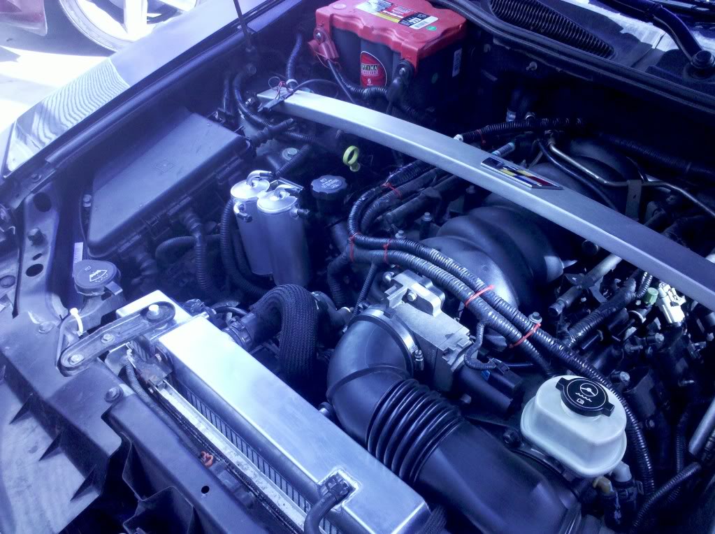
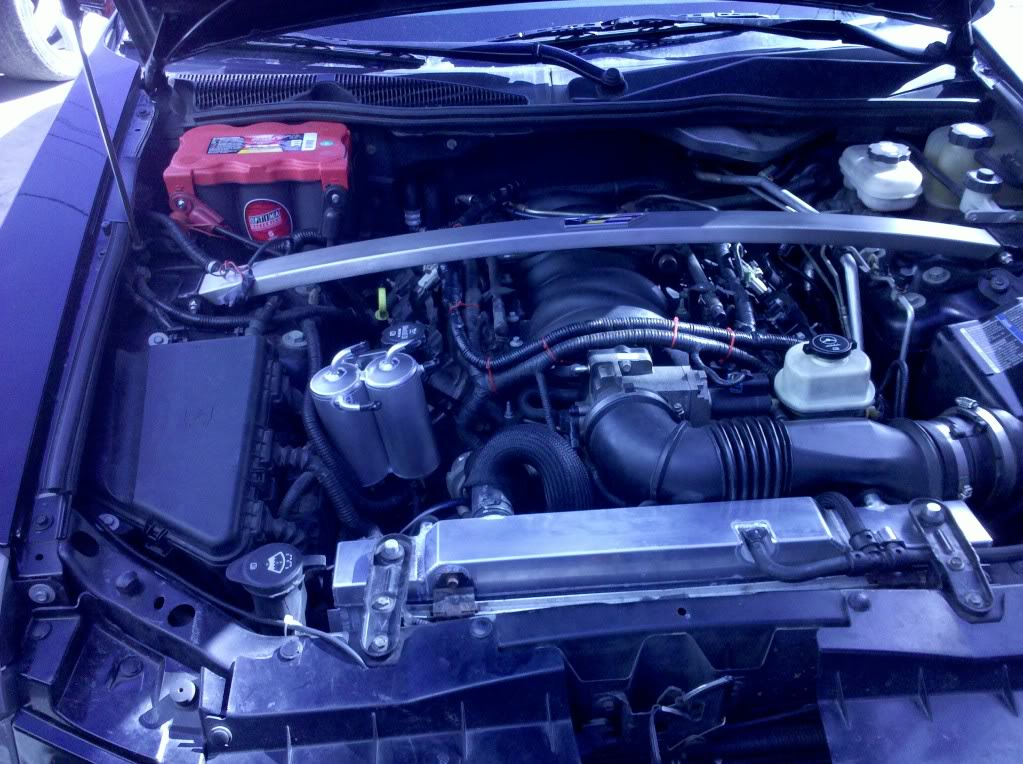
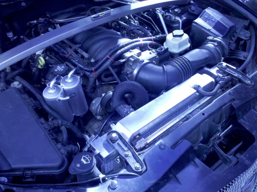
I would recommend that anyone who runs a new wire from the battery to the alternator, that you route differently from stock if you have/will have headers. The OEM cable runs close and can create issues if not paid attention too. Mine melted through, grounded out on the primary, cut a hole in the header and destroyed the alt cable. It's now run over the top of the engine. I can provide a picture or two if interested.
04-17-2013, 08:20 PM
#26
I would recommend that anyone who runs a new wire from the battery to the alternator, that you route differently from stock if you have/will have headers. The OEM cable runs close and can create issues if not paid attention too. Mine melted through, grounded out on the primary, cut a hole in the header and destroyed the alt cable. It's now run over the top of the engine. I can provide a picture or two if interested.
What did you do about the starter cable?
04-17-2013, 09:34 PM
#27
TECH Enthusiast
Join Date: Aug 2007
Location: Wash., DC / Kabul, Afghanistan
Posts: 716
Likes: 0
Received 0 Likes
on
0 Posts
Old pictures. I don't have the car right now, but will in a couple weeks. Anyway, you can see it secured with the red zip ties coming over the top. Starter cable hasn't been touched (that's on the passenger side right? I can't remember off the top of my head).


 04-21-2013, 07:21 PM
#28
TECH Enthusiast
iTrader: (2)

Join Date: Jan 2009
Location: Texas
Posts: 626
Likes: 0
Received 0 Likes
on
0 Posts
There are many lugs you can use. I used MS20659 lugs when I was helping a friend do his BIg 3. However I also had access to the tooling required. This I doubt you will have. Depending on the lug terminal type you use (flat stock vs tube stock) you are going to have crimping / reliability issues without the proper tooling.
04-21-2013, 07:25 PM
#29
There are many lugs you can use. I used MS20659 lugs when I was helping a friend do his BIg 3. However I also had access to the tooling required. This I doubt you will have. Depending on the lug terminal type you use (flat stock vs tube stock) you are going to have crimping / reliability issues without the proper tooling.
04-22-2013, 08:52 PM
#30
TECH Enthusiast
iTrader: (2)
Join Date: Jan 2009
Location: Texas
Posts: 626
Likes: 0
Received 0 Likes
on
0 Posts
I'm not going to leave the stock wiring running in parallel.
While the equivalent impedance would be even less (read: lower voltage drop), the effect would be minor because the impedance differences between the parallel paths would be huge and Ohm's Law would dictate that barely any current would flow in the stock wiring.
While the equivalent impedance would be even less (read: lower voltage drop), the effect would be minor because the impedance differences between the parallel paths would be huge and Ohm's Law would dictate that barely any current would flow in the stock wiring.
With your previous valuations of 1 v at 130 amps, this equals a total resistance of 7.7 mOhms on the factory cabling. This paired with say a 2.5 mOhm cable would produce an overall circuit resistance of 1.88 mOhms. The total voltage drop would equal 0.24V giving you 13.96v at battery with stock alternator.
Also, I would like to know which crimper you are referring to that would meet the requirements of mil spec lugs. Everything I have used has a minimum crimping force of 5.5 tons and is either pneumatic or hydraulic. You will find that an improper indentation in your mil spec lugs will lead to cracking at deformations and weak contacts points at the crimp increasing your impedance. We have tested many electrically powered crimpers and have yet to find one meet the force requirements for 8 AWG, nevermind 1/0.
We need threads like this, it opens eyes I believe to ones theories and practical evaluations.
04-22-2013, 09:23 PM
#31
Please RTM before trying to insult me.
With less than 1/6th the typical DC resistance of 6 gauge, stranded aluminum wiring at 25�C, 1/0 stranded copper wiring will conduct the vast majority of the system's rated ampacity, making the stock wiring largely superfluous and in my estimation, a liability since its insulation is nowhere near the quality of even eco-grade 600V welding cable. Once you add a braided stainless steel shield and clamp on a 1" thick, flat, braided grounding strap, you have good mechanical abrasion protection and EMI shielding of the cable. Sadly, an EMI solution is not so forthcoming for the alternator itself and the coil packs, but I'll take what I can get.
I cannot discuss my job, other to say that I live near Groton. If you're in the market for 10+ ton hydraulic crimping tools, you make want to browse the T&B catalog. I don't have a good copy at home, but I pulled this one up online.
Last edited by FuzzyLog1c; 04-22-2013 at 09:40 PM.
04-23-2013, 06:28 PM
#32
TECH Enthusiast
iTrader: (2)
Join Date: Jan 2009
Location: Texas
Posts: 626
Likes: 0
Received 0 Likes
on
0 Posts
It's a good thing I didn't ask you about your job, otherwise I may have been a little bit upset that you wouldn't share a small piece of information with a friend. All joking aside, you have to realize that this is an open forum and any and all posts are subject to criticism or correction. I didn't want people actually thinking that two electrical paths would make it worse than the original configuration. I understand your reasoning for the EMI protection. So what are your plans to properly ground the over braiding? For a proper EMI shielding, you must ground one or both ends, otherwise you have a pretty metal covering over your wires that provide no functionality.
I browsed through the T&B catalog to make sure I didn't miss something. They do not offer a mil spec crimper other than hydraulic or pneumatic. There are many many other manufactures that have attempted, but have fallen short. And with the costs to seek mil spec certifications, vendors are reluctant to pursue that avenue when there are plenty of commercial consumers purchasing by the lot. With the amount of research you seemed to have put in, I felt that my experience in this field would assist you in ensuring the integrity of the installation. What is the point in putting I the time and effort along with monetary losses to half *** it with the terminals? If you let me know the stud sizes you wish to use, I could send a few MS20659 Class II's your way. I also have Burndy's and Amp's. I also have some M7928 insulated lugs if your interested on a few, they are no longer acceptable for use.
I browsed through the T&B catalog to make sure I didn't miss something. They do not offer a mil spec crimper other than hydraulic or pneumatic. There are many many other manufactures that have attempted, but have fallen short. And with the costs to seek mil spec certifications, vendors are reluctant to pursue that avenue when there are plenty of commercial consumers purchasing by the lot. With the amount of research you seemed to have put in, I felt that my experience in this field would assist you in ensuring the integrity of the installation. What is the point in putting I the time and effort along with monetary losses to half *** it with the terminals? If you let me know the stud sizes you wish to use, I could send a few MS20659 Class II's your way. I also have Burndy's and Amp's. I also have some M7928 insulated lugs if your interested on a few, they are no longer acceptable for use.
04-23-2013, 06:41 PM
#33
I plan on grounding on one side. Ideally, I should try to tie all three grounding straps to the same point, but that's unlikely given the geometry of the engine bay.
As far as lugs go, I don't know what I'm going to pick, because I haven't gotten a good look at how GM did the grounding connections. I suspect that they're using a star washer or something similar to bite into the metal, but if possible, I'd rather polish the contact points and use something like a T&B 256-30695-1162P (wrought copper, two 3/8" bolt, long barrel) and either affix a protective boot or POR-15 the area to keep moisture out. They're expensive ($50 apiece) in low quantities, but that's not a problem.
The other thing I need to solve is a way to quickly switch between the stock-ish Walmart battery that everyone uses (for winter driving) with a Deka ETX20L. Each battery has a different set of terminals.
One other fun idea might involve running 1/0 cable to a centralized location near the rear of the car (probably the fuel pump area). Based on conversations I've had with some of the 750+ RWHP CTS-V1 guys, fueling a tuned-up supercharger is extremely difficult. Many of them wound up putting in several thousand dollars before they arrived at a solution beefy enough to support the massive surges in power (and resultant drops in fuel line pressure). An extra volt or two back there would be a great help.
Last edited by FuzzyLog1c; 04-23-2013 at 06:50 PM.
04-23-2013, 07:01 PM
#34
TECH Enthusiast
iTrader: (2)
Join Date: Jan 2009
Location: Texas
Posts: 626
Likes: 0
Received 0 Likes
on
0 Posts
With the grounding issues some of the V1's have possessed, I wonder of grounding the battery in the rear to a chassis ground would present any issues. With that I mean the difference in calibrated ground potentials for some sensors. I'm curious to know the actual ability to utilize the pressed floor pan as your single sourced ground plane.
04-23-2013, 07:11 PM
#35
TECH Enthusiast
iTrader: (2)
Join Date: Jan 2009
Location: Texas
Posts: 626
Likes: 0
Received 0 Likes
on
0 Posts
For reference, there may be some weight savings available, although neglible. Our aircraft, C-130, utilizes 4 ea 1/0 cables that bond each wing to a centralized point in the aircraft to ensure the same ground potential is present at each motor generator source. And the generators are 90 kVA ea. If corrosion shall present itself at the nodes of the wing to center wing box attach point, you will ensure a proper ground path to the source. Just food for thought, 1/0 may be far more than required for the application, but nonetheless effective.
04-25-2013, 01:57 PM
#36
Automotive star grounding schemes are pointless at this current level unless the frame/body is nonconductive.
Rear grounding has caused 0 issues in the 4+ years I have owned my V with additional rear ground location.
Crimp on connections with large gauge wire definitely require a proper crimper. Proper crimpers are damn pricey but otherwise you loose the benefit of all of that extra copper. We usually torch solder the connection after crimping for good measure. I can't say that the solder helps but in over 20 years I've never had a power wire connector come off or show any issues.
04-25-2013, 04:51 PM
#39
Ok on no over voltage but most pumps are actually rated to run at higher voltages so it is not really "over" voltage. Also, the voltage regulator in the alternator is not designed to regulate the voltage for individual components. It is designed to regulate the voltage for the entire electrical system. By the time the alt responds you will have already run lean.
Now some of the alts that are regulated by the ecm via a pwm signal are faster in response but it is still iffy in my mind that these will respond quickly enough. If you are dead set against a BAP then you might want to consider a cap circuit with a diode to keep the fuel pump voltage up.
Now some of the alts that are regulated by the ecm via a pwm signal are faster in response but it is still iffy in my mind that these will respond quickly enough. If you are dead set against a BAP then you might want to consider a cap circuit with a diode to keep the fuel pump voltage up.
04-25-2013, 05:32 PM
#40
I know someone will respond back that the pump is in parallel with the alt and battery so the voltage sensed by the alt's regulator is the voltage at the fuel pump and therefore a single system wide voltage regulator would be just fine. If all of this was steady state voltages without complex impedances (just resistance) then that assumption would be just fine. However, when voltage levels fluctuate you are not dealing with a strictly DC circuit and therefore you have to consider capacitance and inductance. A component like a fuel pump is going to show a good bit of inductance and this combined with a varying voltage source and a motor spinning 6000 or so rpms makes me think an independent voltage regulator for the fuel pump is a good idea.