2004 CTS-V Procharger build


 11-07-2013, 09:32 PM
#42
Wow, I really didn't realize how long the car has been sitting in the garage unfinished until I looked at the date on this thread! Full time job with travel + MBA nightschool has been kicking my a**. But I finally caught a break and got some work done!
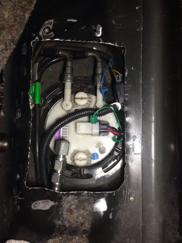
First up, got the return line drilled and tapped into the tank.
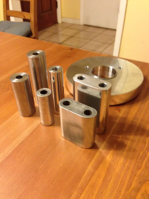
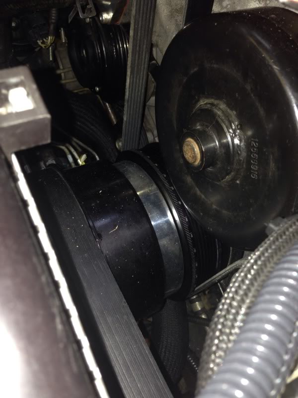
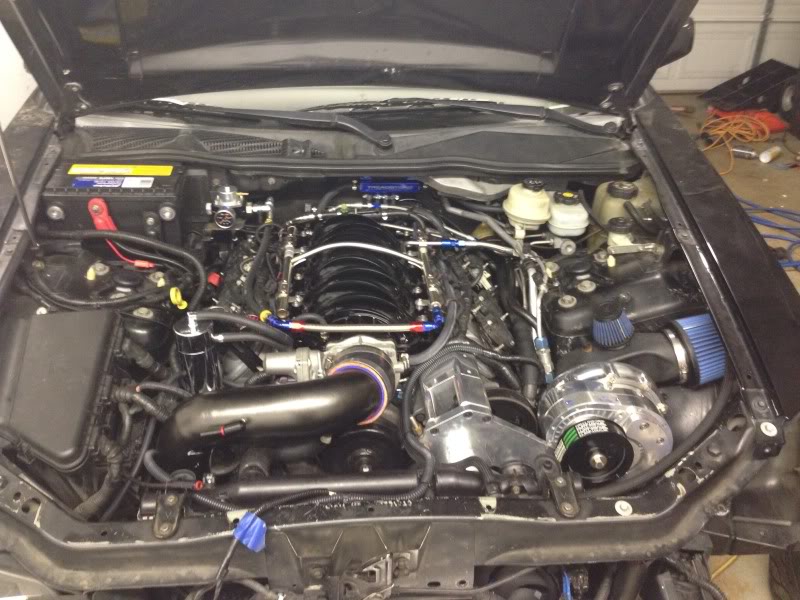
Next, unpacked the custom spacers and I had machined to space out the supercharger an extra 7/8", to better make room for an air filter, compared to the stock pieces sitting in front. It took a little sanding and mothers polish to get them looking good!
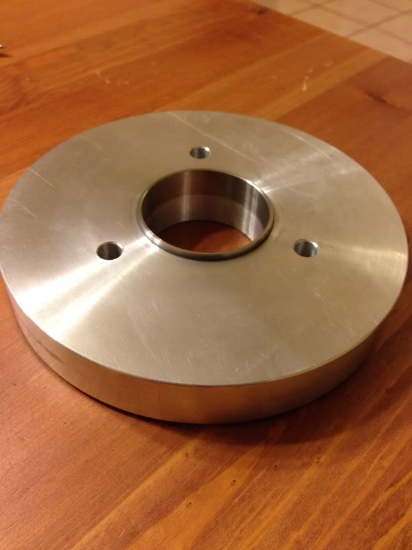
On the pulley spacer, the side shown below has a pressed in stainless steel ring to center it inside the ATI damper hub.
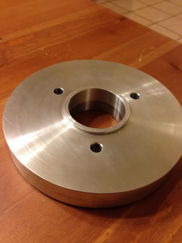
On the reverse side shown below, this lip centers the blower pulley onto the spacer. I did this because I really just didn't like the way the pulley would usually only be centered by the three bolts attaching the pulley to the damper. I like the nice positive location this (should) give. Keep in mind I haven't started the car yet. You can bet your *** I'm nervous that it's all centered!
Not a great pic, but you get the idea:
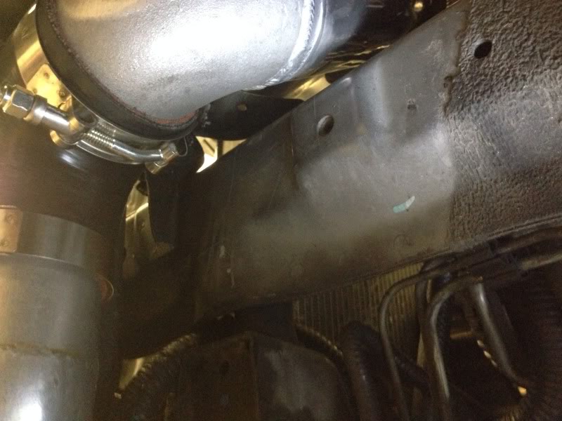
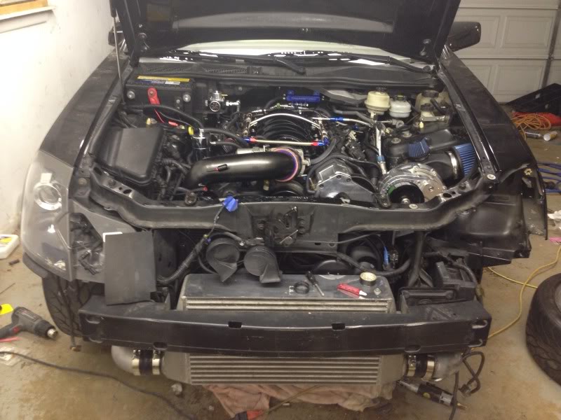
Notice I took up every last bit of room I had. 1/8" clearance to the radiator!
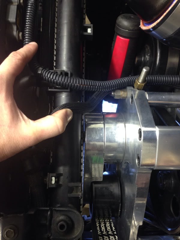
Relocated the power steering cooler.
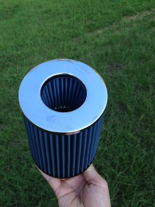
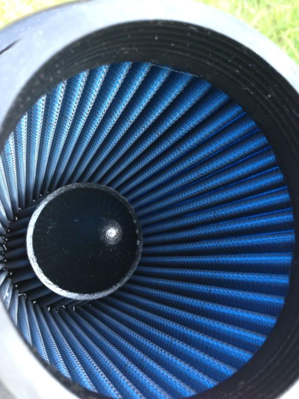
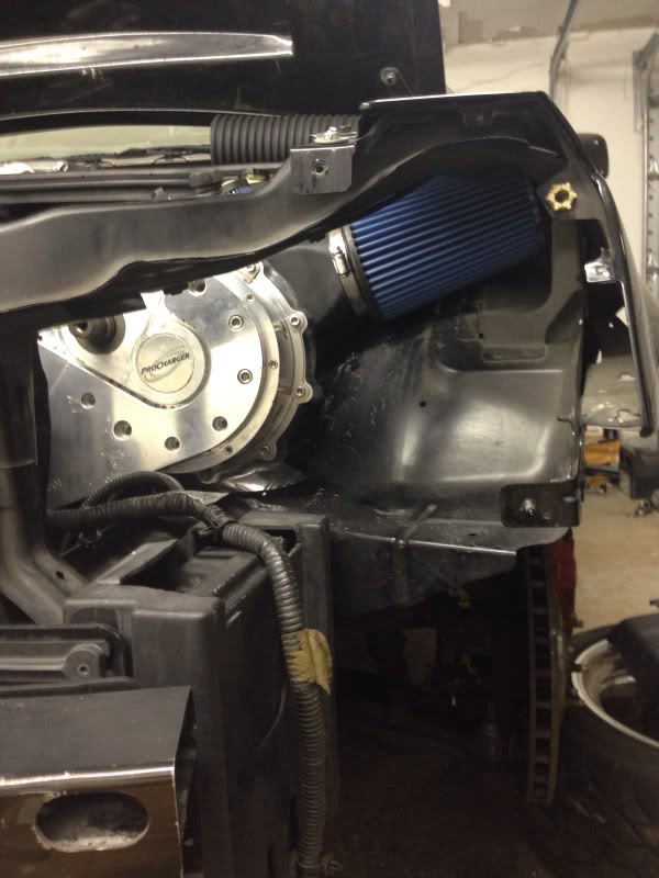
I don't have much room for a filter, but I really like the size and surface area of this one. Amsoil brand if I remember right.
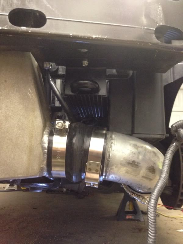
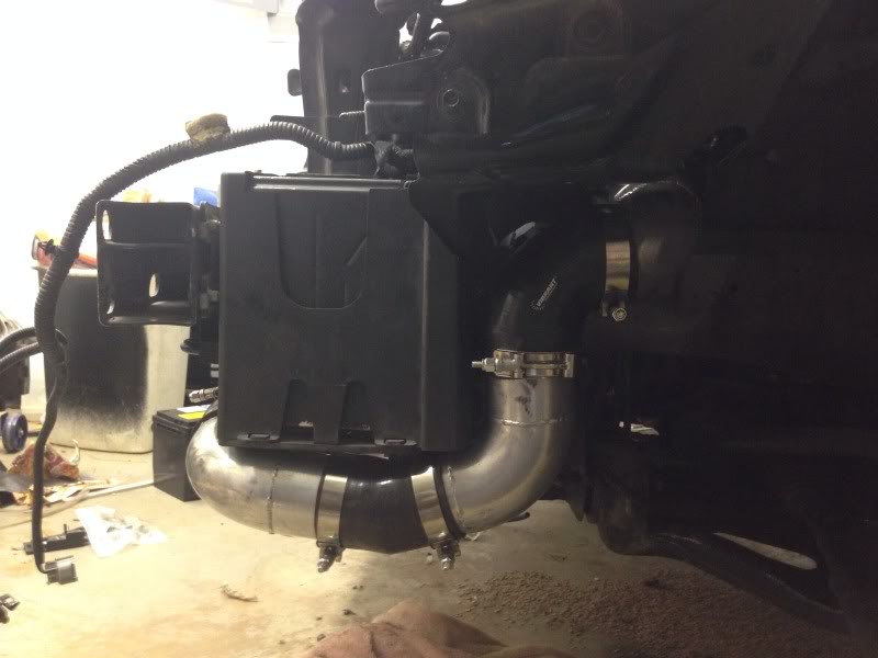
Basic fitment shots:
And the finale! I will reconnect the battery sometime this weekend to check for leaks. Test fire the engine to make sure there is nothing obviously screwed up, and then I'm off to East Texas Muscle Cars for a tune next Friday!
First up, got the return line drilled and tapped into the tank.

Next, unpacked the custom spacers and I had machined to space out the supercharger an extra 7/8", to better make room for an air filter, compared to the stock pieces sitting in front. It took a little sanding and mothers polish to get them looking good!

On the pulley spacer, the side shown below has a pressed in stainless steel ring to center it inside the ATI damper hub.

On the reverse side shown below, this lip centers the blower pulley onto the spacer. I did this because I really just didn't like the way the pulley would usually only be centered by the three bolts attaching the pulley to the damper. I like the nice positive location this (should) give. Keep in mind I haven't started the car yet. You can bet your *** I'm nervous that it's all centered!

Not a great pic, but you get the idea:

Notice I took up every last bit of room I had. 1/8" clearance to the radiator!

Relocated the power steering cooler.

I don't have much room for a filter, but I really like the size and surface area of this one. Amsoil brand if I remember right.


Basic fitment shots:


And the finale! I will reconnect the battery sometime this weekend to check for leaks. Test fire the engine to make sure there is nothing obviously screwed up, and then I'm off to East Texas Muscle Cars for a tune next Friday!


 11-08-2013, 07:18 AM
#46
Nice pieces! I bet whoever made those for you could make more for anyone else planning on running f1a in their V. This is why I dont plant on surpassing the d1sc capabilities. Also, im curious of it fitting with an aluminum radiator. Love the progress! Can't wait to see some numbers!
11-08-2013, 07:21 AM
#47
I have a theory on the rear diff. I tore my old one apart just out of curiosity. On the drivers side of the diff the bearing race in the cover is not a continuous piece. There is about a 1/2 inch gap in the race. The opposite side has a solid bearing race. Those two race surfaces are essentially what float the carrier inside the housing. If the case gets hot or excess force is applied is it possible that the bearing race with the gap expands causing the entire carrier to be misaligned inside the case leading to the exploded cases? I'm not sure why it would have been designed that way in the first place. I would think a solid bearing race on the cover side could prevent some of the expansion and explosion. Just my thoughts after tearing one apart.
11-08-2013, 10:51 AM
#50
TECH Regular
iTrader: (14)

Join Date: Jan 2009
Location: Cypress TX
Posts: 422
Likes: 0
Received 0 Likes
on
0 Posts
Really like that your using the A&A corvette fuel system... I've been on the fence between cramming a second DW300 in the bucket or the A&A kit with a 044. I'll be watching for results.
Last edited by GulfM3; 11-08-2013 at 02:39 PM.
11-08-2013, 11:03 AM
#51
Yea I put 3 gallons of fuel in it last night and the fittings are NOT leaking, which makes me feel at least a little better. I was nervous given the vette tank is a thick layer of a solid material, while the V is two layers of two different materials.
I will let you know how it goes...
11-08-2013, 05:31 PM
#53
TECH Fanatic

A lot more work that I would want to do to the car myself. I get frustrate quickly sometimes. Well done on the build so far. Do you have an over under on the boost you want to run after everything is dialed in?
11-08-2013, 09:57 PM
#55
The intake will be more restrictive, but it is reversible, and I can always change it up later! The crank piece is a solid chunk of aluminum... I'd guess ~5 lb. About the same weight as the blower pulley itself. I actually thought about putting it on a diet while it was on the lathe... but really decided the less I did the better in terms of getting zero balance.
11-09-2013, 02:45 PM
#57
IT'S ALIIIIIIVE!!
Ha ha, and only a couple small fuel fittings needed tightening. All else looks good! I still need to check lots of things... but at least I got to hear it run!
My wife's response when I walked in the house? "What the hell was that?!?"
Ha ha, and only a couple small fuel fittings needed tightening. All else looks good! I still need to check lots of things... but at least I got to hear it run!
My wife's response when I walked in the house? "What the hell was that?!?"
Last edited by 1BADCTS; 11-09-2013 at 03:11 PM.
