

'70 Nova LY6/TH400 6.0VVT
 09-24-2018, 06:32 AM
#1601


Problem I have is being so low my collector and y make contact far more regular than not. The slip fit torca combo at the collector was slipping off due to the tug effect which was causing occasional leaks ( once per month ) and required tightening back up and away I went. I tightened so much I broke the bolts, drilled em out and put 1/2" grade 16 in there to grip it tighter. Now the slip stopped but the ground contact distorted the torca on the collector making it VERY hard to remove, almost impossible without cutting. The torca I use on the mid pipe over the axle to make service easy? Still holds perfect, never leaks, slips apart like butta. Its only the low hangers that give me grief. Previous headers I had the car lower, made more contact, used ball and socket and aside from snapping a bolt once, never an issue with leaks or remove/install service. Had the car 25 years so... lots of service
 09-24-2018, 10:45 AM
#1602
Thanks for all the input guys. None of these clamps are designed to be drug over a speedbump with a car on top of them, so I don't have high expectations regardless. The V-band is hanging down maybe 3/4" from the tube OD. A Torca will probably still hang down about 1/4". That 1/2"ish improvement could make all the difference coming out of my driveway, but it's not going to help me with every speed bump and parking lot entrance out there. I'm just going to have to build a twin turbo setup and tuck some oval tubing in there - pretty much the only acceptable solution to this problem 

 09-26-2018, 11:52 AM
#1606
While I'm waiting for a new v-band clamp as a temporary fix, I decided to get back to work on the AC project.
Here is my to do list:
- Adjust POA valve
- Flush evaporator and POA valve
- Install o-rings throughout
- Install hi pressure switch
- Add PAG oil
- Wire compressor and fan relay
- Install compressor belt
- Evacuate and charge
Starting with the POA valve, I recently picked up the 1970 chassis service manual which has all kinds of great info on how the AC system works as well as diagnostics and repair. Per the service manual, the valve setpoint from the factory was 29.5psig at sea level and that appears to be where mine was adjusted. To get roughly the same evaporator temperature from R134a as I would have had with R12, I would need to adjust the POA down to about 27psig, however after a little discussion and reading up on the auto ac forum I've decided to target a lower pressure of 26psig. This will give a freon temperature of about -1C or 30F which is technically below the freezing point of water, but with warmer air flowing over the evaporator it's still very unlikely to ice up and should give better cooling performance.
Here is a video explaining the POA adjustment. I used a 3/8" socket to loosen the lock nut and a 7/32" socket to adjust the setscrew.
It was really hard to see the gauge or line up the camera phone while taking video, so I went back and snapped a photo to show it indeed was set at 26psi.

Satisfied with the POA adjustment, I took it off the system and got setup to flush the evaporator. Flushing removes any residuals of the old lubricant and R12 residuals that may not play well with the new R134a, as well as cleans out any debris that may have accumulated while the system has been unsealed for the last twenty years. I used an aerosol flush called A/C Pro "Power Clean and Flush". Below is a photo showing how I set it up. The flush is fed into the outlet of the evaporator and I used clear poly tubing at the evaporator inlet to a plastic container under the car. That allowed me to monitor the color/cleanliness of fluid coming out. Once I ran all the flush through, I blew it out with air.

Below is a video showing some of the process. When I went to air blow the system, some of the flush was forced out of the small oil bypass line so I added another tube to route that down to my collection container. The function of the oil bypass line is to make sure oil in the system is always allowed to circulate back to the compressor even if the POA valve is mostly closed.
Here is my collection container showing the amount of flush that went through the system and the resulting color. The amber color of the fluid is mostly from the first few seconds of flushing when the flush came out pretty dark.


Not photographed, I also flushed the POA valve on the bench into a bucket. This concludes my presentation for today.
Here is my to do list:
- Adjust POA valve
- Flush evaporator and POA valve
- Install o-rings throughout
- Install hi pressure switch
- Add PAG oil
- Wire compressor and fan relay
- Install compressor belt
- Evacuate and charge
Starting with the POA valve, I recently picked up the 1970 chassis service manual which has all kinds of great info on how the AC system works as well as diagnostics and repair. Per the service manual, the valve setpoint from the factory was 29.5psig at sea level and that appears to be where mine was adjusted. To get roughly the same evaporator temperature from R134a as I would have had with R12, I would need to adjust the POA down to about 27psig, however after a little discussion and reading up on the auto ac forum I've decided to target a lower pressure of 26psig. This will give a freon temperature of about -1C or 30F which is technically below the freezing point of water, but with warmer air flowing over the evaporator it's still very unlikely to ice up and should give better cooling performance.
Here is a video explaining the POA adjustment. I used a 3/8" socket to loosen the lock nut and a 7/32" socket to adjust the setscrew.
It was really hard to see the gauge or line up the camera phone while taking video, so I went back and snapped a photo to show it indeed was set at 26psi.
Satisfied with the POA adjustment, I took it off the system and got setup to flush the evaporator. Flushing removes any residuals of the old lubricant and R12 residuals that may not play well with the new R134a, as well as cleans out any debris that may have accumulated while the system has been unsealed for the last twenty years. I used an aerosol flush called A/C Pro "Power Clean and Flush". Below is a photo showing how I set it up. The flush is fed into the outlet of the evaporator and I used clear poly tubing at the evaporator inlet to a plastic container under the car. That allowed me to monitor the color/cleanliness of fluid coming out. Once I ran all the flush through, I blew it out with air.
Below is a video showing some of the process. When I went to air blow the system, some of the flush was forced out of the small oil bypass line so I added another tube to route that down to my collection container. The function of the oil bypass line is to make sure oil in the system is always allowed to circulate back to the compressor even if the POA valve is mostly closed.
Here is my collection container showing the amount of flush that went through the system and the resulting color. The amber color of the fluid is mostly from the first few seconds of flushing when the flush came out pretty dark.
Not photographed, I also flushed the POA valve on the bench into a bucket. This concludes my presentation for today.
10-01-2018, 11:18 AM
#1607
Yesterday I installed the POA suction valve and the new TXV with fresh o-rings throughout. The new TXV is not application-specific so the capillary tube for the sending bulb and the external equalizer line are much longer than they need to be. This results in some ugly coiled-up tubing, but at least the TXV is calibrated properly for R134a. I clamped the sensing bulb on top of the evaporator outlet using the original clamps.

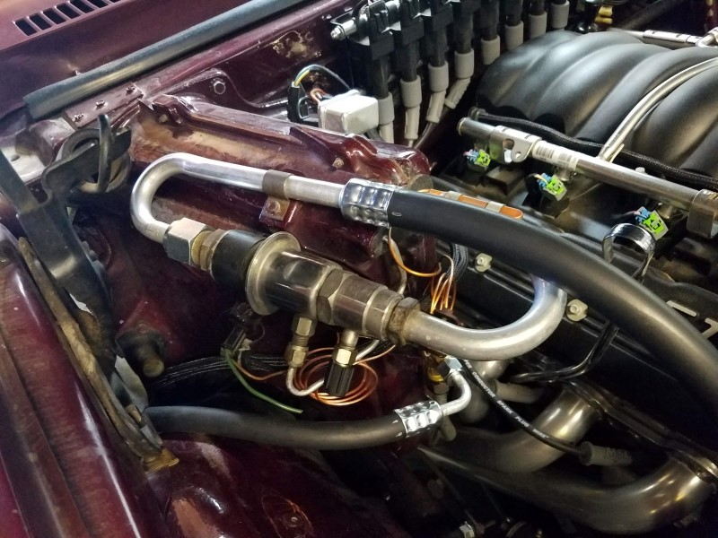
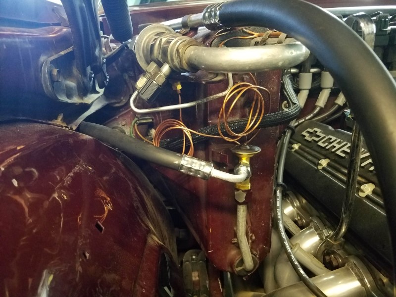
The sensing bulb must be insulated from the engine compartment otherwise it will react to fluctuating engine compartment temperatures and radiator wash instead of the evaporator. This requires the use of an insulation tape commonly referred to as Prestite. I ordered a foot of tape from Nostalgic Auto Air when I purchased a few other components. I was a bit confused because the tape has a white wax-paper backing on one side that removes easily and a clear cellophane cover on the other side that looks like it should be removed, but was terribly difficult to get off. I confirmed today the clear covering is meant to stay just on to keep it clean.

Tonight I'll wrap the bulb and continue working to seal up the system. I have yet to install o-rings at the compressor and condenser and I also need to add compressor oil. Then I can work on wiring. My plan is to use a relay so the radiator fan is always on high when the compressor is on. Power to both the relay and the compressor clutch will be provided through the ambient temperature switch and hi/lo switch installed in the drier. The ambient temp switch will prevent compressor activation under 37F ambient tempt. The hi/lo switch will shut off the compressor for excess/unsafe pressure or undercharge.
The sensing bulb must be insulated from the engine compartment otherwise it will react to fluctuating engine compartment temperatures and radiator wash instead of the evaporator. This requires the use of an insulation tape commonly referred to as Prestite. I ordered a foot of tape from Nostalgic Auto Air when I purchased a few other components. I was a bit confused because the tape has a white wax-paper backing on one side that removes easily and a clear cellophane cover on the other side that looks like it should be removed, but was terribly difficult to get off. I confirmed today the clear covering is meant to stay just on to keep it clean.
Tonight I'll wrap the bulb and continue working to seal up the system. I have yet to install o-rings at the compressor and condenser and I also need to add compressor oil. Then I can work on wiring. My plan is to use a relay so the radiator fan is always on high when the compressor is on. Power to both the relay and the compressor clutch will be provided through the ambient temperature switch and hi/lo switch installed in the drier. The ambient temp switch will prevent compressor activation under 37F ambient tempt. The hi/lo switch will shut off the compressor for excess/unsafe pressure or undercharge.
Last edited by -TheBandit-; 10-01-2018 at 11:54 AM.
10-09-2018, 11:24 AM
#1608
With the days getting shorter, I've been doing a lot more night driving in the Nova. I learned my original tail lights were very unreliable. The passenger tail light would not ground properly through the housing and would periodically just stop working altogether. Cleaning the contact and jiggling the socket could sometimes get it working again but before long it would be out. The driver tail light had it's own issue - sometimes the brake/signal would not work at all even though the bulb was fine. That means sometimes I had no brake lights at all and just one of two running lights!
My path home involves stopping and turning from 50mph traffic without a dedicated turn lane. Recently every time I made that turn I was bracing for the car behind to plow right through me, not knowing if my tail lights had stopped working during the drive. I came home the other night with that top of mind and sure enough when I checked neither of my tail lights were working. That was the last straw! I ordered a pair of Easy Performance LED panels right away.
Here is a side-by-side photo of the running lights with the passenger side LED panel installed vs the driver's side original.

As you can see above the Easy Performance LED panels illuminate the ENTIRE tail light lens while the factory bulbs only light up about 1/3 of the lens. The panels use red LEDs so even the clear reverse lamp lens can illuminate red. That is the main reason I chose these panels - maximum visibility. Now on to the installation....
Easy Performance LED Panel Installation
The first step to install was removing and disassembling the tail lights. To get them out I had to loosen all the bumper bolts and then there are just a few nuts holding them on from inside the trunk. The lenses are attached by 4 shoulder screws and they can stick to the gasket inside the housing, so I pushed my thumb through the bulb opening to pop them out from behind.
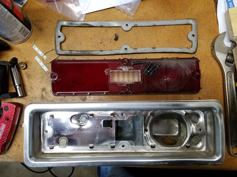
The factory housings have a couple of bent-up tabs that I assume are used to mask light from the tail and backup lamps. These protrude and would interfere with a flat LED panel so they need to be bent down using pliers and a hammer (with the housing backed by wood).


There is also a piece of plastic protruding from the reverse lens that needs to be clipped and filed flat.


The lights wire to the factory bulb sockets (more on that later), but they have one extra wire that's used to get ign+ power for sequential operation. That wire needs a pass through, so the housing can be drilled near the reverse bulb socket opening and a grommet installed.


A this point the inside of the housing needs to be cleaned well so the LED panel can adhere using double sided adhesive. Rubbing alcohol works well followed by a little dry time to keep the rubbing alcohol residue from affecting the adhesive. This is also a good time to clean the inside of the tail light lens with some dish soap and a brush. Now the wires can be passed through their respective openings.

Next the LED panel can be roughly positioned along one edge against the small gasket-retaining tabs in the housing. With the panel tilted up you can see where each of the 3 double sided adhesive strips are located to attach the panel. The backing can now be peeled off and the LED panel pressed into place in each of those locations.


Now it's just a matter of reassembling the tail light and putting it back in the car.


After finishing the installation I found I still had a few problems with the original tail light sockets. The spring contacts inside the sockets were too short to make reliable contact with the new bulb sockets and the entire socket was still pretty corroded. I was able to correct that by cleaning all the contact surfaces with a Dremel and then using small needle nose pliers to pull out the spring contacts until they made a stronger connection. This step probably would have fixed the problem I was having with my original passenger brake/signal light. But it would not have fixed the ground issue. One benefit of the new LED panels is they use both the reverse socket and tail socket ground connections which provides redundancy.
I should note that the use of bulb sockets on these panels is entirely for convenience of installation. There is no reason you couldn't clip the wires and connect them directly. I'm sure that would provide more reliable connection and I might consider going that route if I have more problems with these sockets in the future.
Last 2018 Santa Paula Cruise Night
With the new LEDs out back, I set off to the last Santa Paula cruise night of 2018. I knew it would get dark before I left for the 30min drive home and it was great knowing the car would be extra visible now. Peace of mind!


My path home involves stopping and turning from 50mph traffic without a dedicated turn lane. Recently every time I made that turn I was bracing for the car behind to plow right through me, not knowing if my tail lights had stopped working during the drive. I came home the other night with that top of mind and sure enough when I checked neither of my tail lights were working. That was the last straw! I ordered a pair of Easy Performance LED panels right away.
Here is a side-by-side photo of the running lights with the passenger side LED panel installed vs the driver's side original.
As you can see above the Easy Performance LED panels illuminate the ENTIRE tail light lens while the factory bulbs only light up about 1/3 of the lens. The panels use red LEDs so even the clear reverse lamp lens can illuminate red. That is the main reason I chose these panels - maximum visibility. Now on to the installation....
Easy Performance LED Panel Installation
The first step to install was removing and disassembling the tail lights. To get them out I had to loosen all the bumper bolts and then there are just a few nuts holding them on from inside the trunk. The lenses are attached by 4 shoulder screws and they can stick to the gasket inside the housing, so I pushed my thumb through the bulb opening to pop them out from behind.
The factory housings have a couple of bent-up tabs that I assume are used to mask light from the tail and backup lamps. These protrude and would interfere with a flat LED panel so they need to be bent down using pliers and a hammer (with the housing backed by wood).
There is also a piece of plastic protruding from the reverse lens that needs to be clipped and filed flat.
The lights wire to the factory bulb sockets (more on that later), but they have one extra wire that's used to get ign+ power for sequential operation. That wire needs a pass through, so the housing can be drilled near the reverse bulb socket opening and a grommet installed.
A this point the inside of the housing needs to be cleaned well so the LED panel can adhere using double sided adhesive. Rubbing alcohol works well followed by a little dry time to keep the rubbing alcohol residue from affecting the adhesive. This is also a good time to clean the inside of the tail light lens with some dish soap and a brush. Now the wires can be passed through their respective openings.
Next the LED panel can be roughly positioned along one edge against the small gasket-retaining tabs in the housing. With the panel tilted up you can see where each of the 3 double sided adhesive strips are located to attach the panel. The backing can now be peeled off and the LED panel pressed into place in each of those locations.
Now it's just a matter of reassembling the tail light and putting it back in the car.
After finishing the installation I found I still had a few problems with the original tail light sockets. The spring contacts inside the sockets were too short to make reliable contact with the new bulb sockets and the entire socket was still pretty corroded. I was able to correct that by cleaning all the contact surfaces with a Dremel and then using small needle nose pliers to pull out the spring contacts until they made a stronger connection. This step probably would have fixed the problem I was having with my original passenger brake/signal light. But it would not have fixed the ground issue. One benefit of the new LED panels is they use both the reverse socket and tail socket ground connections which provides redundancy.
I should note that the use of bulb sockets on these panels is entirely for convenience of installation. There is no reason you couldn't clip the wires and connect them directly. I'm sure that would provide more reliable connection and I might consider going that route if I have more problems with these sockets in the future.
Last 2018 Santa Paula Cruise Night
With the new LEDs out back, I set off to the last Santa Paula cruise night of 2018. I knew it would get dark before I left for the 30min drive home and it was great knowing the car would be extra visible now. Peace of mind!
10-09-2018, 11:27 AM
#1609
TECH Senior Member

Lookin' GOOD Clint! STILL love those wheels!
 10-09-2018, 12:29 PM
#1612
Launching!
Awesome!! I have had those tail lights book marked for months now waiting to pull the trigger! They are the only ones that I have found that use the whole tail light assembly. Thanks for posting a how to!! Can you do a quick video of the sequential blinker?
 10-09-2018, 01:41 PM
#1614
Here is a video from Easy Performance showing the different sequences that can be used for turn signals. Mine aren't functioning yet because I need to run a switched ign+ wire to the back of the car for this to work. Right now mine function like standard on/off brakes/signals.
:]https://www.youtube.com/watch?v=MgEY87BOYGs
First I'll say both are probably good options, especially since the Digi-Tail design appears to have changed to add a panel on either side of the backup lens (the original design from my memory was just a panel in the original brake/turn bulb area).
There are a few reasons that I went with Easy Performance instead of Digi-Tails: More sequencing pattern options and ones I liked better which involved the entire lens and not just part of the lens. Easier hookup with the bulb socket / much simpler wiring harness (Digi-Tails have a lot of wire splices). One-piece PCB that goes all the way across and illuminates across the reverse lens red for running and brake (turns white for backup lights) (Digi-Tails uses multiple separate PCBs which also complicates wiring and only illuminates left and right of the reverse lense) Very responsive customer support when I called to discuss function and install. One thing I saw in the Digi-Tails instructions is that it does not require you to hammer down those protruding tabs so if that's something that bothers you, Digi-Tails have an advantage there.
Until recently the Digi-tails product did not include a panel for both halves of the tail light. I couldn't find any video to see how their newer design operates. Even on their own website they only show the old design which only illuminated about 1/3 of the lens for turn signals. This is a video of what I think is their old design:
Last edited by -TheBandit-; 10-10-2018 at 05:43 PM.
10-17-2018, 12:39 PM
#1615
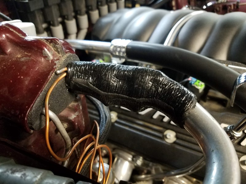
Continuing work on my AC system, I managed to wrap the TXV sensing bulb with a layer of insulation tape (aka cork tape or prestite tape). The insulation prevents the TXV from responding to engine bay and fan-wash temperatures.

Then I installed o-rings throughout the system and added compressor oil. I decided to use PAG46 because that is what's called for by the compressor. I added the oil through the suction port and rotated the compressor by hand to draw it into the system. The oil I'm using is NAPA Premium which is a house-labelled bottle of Dow chemical Ucon 244.

Now that the system is completely sealed up, I can turn my attention to the wiring. For the compressor, my strategy is to use the original, non-cycling control method which will run the compressor any time the switch on the dash is set to an ac-demanding mode (Max, Norm, Defrost, etc). Cycling systems turn the clutch on and off to prevent low evaporator pressures from freezing up the system, but with this system the POA valve ensures the evaporator pressure is always high enough to prevent freeze-up. The TXV and POA valve regulate the flow of refrigerant so the compressor can run continuously.
In addition to the compressor control strategy, I needed to decide how to operate the engine fan. I've decided to run the fan at high speed any time the AC compressor is running. This is a "brute force" method of operating the fan, but it will ensure the refrigerant is condensed and supercooled as much as possible and that the engine will get maximum cooling as well. The drawback is fan noise, electrical draw and wear will always be at their highest even in low cooling demand such as when running the defroster or lower blower speeds. An alternative strategy is to use a trinary switch which would only turn the engine fan on if the system reached a high enough operating pressure (indicating higher cooling demand). I decided against this because from what I could tell, all the trinary switches on the market had relatively high pressure thresholds, for example the Vintage Air trinary switch would not turn on the fan until 254psi. I'd be concerned at that point that I would not have adequate capacity and the evaporator pressure (and temperature) might start to climb.
Currently the ECM controls a 2 speed engine fan based on engine coolant temperature. To trigger the fan relay, it provides ground signals for high or low speed. I am using a Volvo fan relay and found it will run high speed as long as the high input is grounded, regardless of whether or not the low speed input is grounded. My goal is for the fan control to operate normally with ECM control whenever the AC system isn't running,but override the ECM control when the AC is running. To do so I plan to wire in a relay to control the fans as shown below:

Here is how I think this will operate:
Operation with AC Ctrl OFF:
- AC Fan Ctrl Relay and AC Compressor De-energized. ECM Hi Fan Signal provides ground to Hi Speed Fan Ctrl Relay to turn Engine Hi Fan on/off based on ECM control
Operation with AC Ctrl ON:
- AC Fan Ctrl Relay and AC Compressor Energized. AC Fan Ctrl Relay provides ground to Hi Speed Fan Ctrl Relay to turn Engine Hi Fan On whenever AC is running. Compressor runs at all times that AC Ctrl is On (non-cycling system).
- The ECM signal input is "floating" (i.e. not connected to ground or a load). Hopefully this does not trigger any ECM diagnostic codes.
- If the Ambient Temp Switch senses freezing air temperatures, the control reverts to “AC Off”.
- If refrigerant pressure goes below 30psi, the Hi/Low Pressure Switch opens, the control reverts to "AC Off"
- If refrigerant pressure goes above 406psi, the Hi/Low Pressure Switch opens, the control reverts to "AC Off"
I plan to wire this thing over the next couple days and hopefully I'll be ready to put a charge into the system by the end of the month.
Then I installed o-rings throughout the system and added compressor oil. I decided to use PAG46 because that is what's called for by the compressor. I added the oil through the suction port and rotated the compressor by hand to draw it into the system. The oil I'm using is NAPA Premium which is a house-labelled bottle of Dow chemical Ucon 244.
Now that the system is completely sealed up, I can turn my attention to the wiring. For the compressor, my strategy is to use the original, non-cycling control method which will run the compressor any time the switch on the dash is set to an ac-demanding mode (Max, Norm, Defrost, etc). Cycling systems turn the clutch on and off to prevent low evaporator pressures from freezing up the system, but with this system the POA valve ensures the evaporator pressure is always high enough to prevent freeze-up. The TXV and POA valve regulate the flow of refrigerant so the compressor can run continuously.
In addition to the compressor control strategy, I needed to decide how to operate the engine fan. I've decided to run the fan at high speed any time the AC compressor is running. This is a "brute force" method of operating the fan, but it will ensure the refrigerant is condensed and supercooled as much as possible and that the engine will get maximum cooling as well. The drawback is fan noise, electrical draw and wear will always be at their highest even in low cooling demand such as when running the defroster or lower blower speeds. An alternative strategy is to use a trinary switch which would only turn the engine fan on if the system reached a high enough operating pressure (indicating higher cooling demand). I decided against this because from what I could tell, all the trinary switches on the market had relatively high pressure thresholds, for example the Vintage Air trinary switch would not turn on the fan until 254psi. I'd be concerned at that point that I would not have adequate capacity and the evaporator pressure (and temperature) might start to climb.
Currently the ECM controls a 2 speed engine fan based on engine coolant temperature. To trigger the fan relay, it provides ground signals for high or low speed. I am using a Volvo fan relay and found it will run high speed as long as the high input is grounded, regardless of whether or not the low speed input is grounded. My goal is for the fan control to operate normally with ECM control whenever the AC system isn't running,but override the ECM control when the AC is running. To do so I plan to wire in a relay to control the fans as shown below:
Here is how I think this will operate:
Operation with AC Ctrl OFF:
- AC Fan Ctrl Relay and AC Compressor De-energized. ECM Hi Fan Signal provides ground to Hi Speed Fan Ctrl Relay to turn Engine Hi Fan on/off based on ECM control
Operation with AC Ctrl ON:
- AC Fan Ctrl Relay and AC Compressor Energized. AC Fan Ctrl Relay provides ground to Hi Speed Fan Ctrl Relay to turn Engine Hi Fan On whenever AC is running. Compressor runs at all times that AC Ctrl is On (non-cycling system).
- The ECM signal input is "floating" (i.e. not connected to ground or a load). Hopefully this does not trigger any ECM diagnostic codes.
- If the Ambient Temp Switch senses freezing air temperatures, the control reverts to “AC Off”.
- If refrigerant pressure goes below 30psi, the Hi/Low Pressure Switch opens, the control reverts to "AC Off"
- If refrigerant pressure goes above 406psi, the Hi/Low Pressure Switch opens, the control reverts to "AC Off"
I plan to wire this thing over the next couple days and hopefully I'll be ready to put a charge into the system by the end of the month.
Last edited by -TheBandit-; 10-17-2018 at 03:18 PM.
10-19-2018, 01:27 PM
#1616
TECH Fanatic
iTrader: (27)

Is there anyway to wire it in a way that allows the ECU to control any of those functions? I have researched for the 0411 Gen3 OS and there is a resistor that you could wire to into the factory connector so that the ECU thinks the pressure is right in the lines to allow for it to control the fans and input functions from the cabin. In my scenario the Vintage Air unit would control the actual functions of AC circuit as far as pressure and turning the compressor on and off. Then the ECU could control the fans and could turn off the fans if RPM was too high.
I started working through the wiring on this setup, but never completed. I could share it with you if you like. Did you have any form of RPM protection for the compressor in your diagram?
I started working through the wiring on this setup, but never completed. I could share it with you if you like. Did you have any form of RPM protection for the compressor in your diagram?
10-19-2018, 03:21 PM
#1617
I thought using the ECM but with the potential complications of the Gen IV E38 ECU and operating system, I just felt it was best to make the AC and fan stand-alone w/ the 1970 factory controls. There is no "AC Request" like on the earlier ECMs - on the E38 everything would be done by serial communication with a BCM which I don't have. I also don't know if the setpoints for compressor cycling or fans would be appropriate for my system. It was a conscious choice to simplify the wiring/controls aspect.
As far as RPM protection, no there is nothing to keep the compressor from going overspeed beyond the engine rev limiter. It's going to go as fast as the belt drives it as long as the AC is on and the operating pressures don't trigger the binary switch. I don't plan to do high RPM pulls with my AC running, but if it does happen occasionally I don't expect it would hurt anything.
As far as RPM protection, no there is nothing to keep the compressor from going overspeed beyond the engine rev limiter. It's going to go as fast as the belt drives it as long as the AC is on and the operating pressures don't trigger the binary switch. I don't plan to do high RPM pulls with my AC running, but if it does happen occasionally I don't expect it would hurt anything.
10-20-2018, 10:33 AM
#1618
TECH Enthusiast

At best your POA and your txv will probably be fighting each other and your pressures will be wonky. If you have a fixed compressor setup you need something to cycle it or it will burn up your compressor trying to run it 100%. A simple solution for your problem is to use a 77-79 evaporator from a Nova which will bolt in and convert your system to a orifice tube setup. You can then put a S10 hard line, accumulator, and condensor in as needed. S10's used both fixed and variable compressors so you can mix and match to your needs. You can have a pressure sensor and an accumulator that has a fitting for a low pressure cutout switch if you have a fixed compressor. The system will read the pressure sensor and it turn on your fans and give you fan control regardless of it not having an ac request but there will be no rpm protection. The low pressure cutout would cycle your compressor as needed and you could wire that in line with your ac request to turn on the compressor. If you needed a evaporator you could also use a S10 which fit in nicely. You could do this for about $60 condensor, $25 hardline, $20 accumulator, and about $80 for a evaporator. This would have saved you $$$ in the long run and make it into a more modern system with no second guessing on how it's going to work.
If you want to try to keep the txv valve you would still need to ditch the POA and then put in a thermo cycling switch. This is how vintage does it. Based on where you are it looks like you can take it out and just hook your line directly to the evaporator.
If you want to try to keep the txv valve you would still need to ditch the POA and then put in a thermo cycling switch. This is how vintage does it. Based on where you are it looks like you can take it out and just hook your line directly to the evaporator.
Last edited by 69 Ghost; 10-20-2018 at 11:04 AM.
10-20-2018, 12:04 PM
#1619
69 Ghost I respectfully disagree with you but I appreciate your input.
Yes there are POA eliminator systems that replace the POA with a cycling switch. The reason they cycle the system is to prevent low evaporator pressures which would freeze the evaporator. These kits came about mainly because they are a cheap and simple replacement for a POA valve, not because they perform better or are needed to make the factory system run properly.
In my system the POA regulates evaporator pressure to a constant minimum, ensuring it does not freeze up while remaining at the lowest possible saturation temperature. When the compressors is running continuously the operating pressures do not spike and drop back and forth as they do on a cycling system. It's actually easier on the compressor from that standpoint as well as the clutch. More bearing and seal wear from running constantly, but many fewer start/stops and under lower pressures.
The idea that the POA and TXV fight eachother is not correct when the two are operating properly. The TXV meters based on superheat. The POA regulates based on pressure. This is how the original system was designed to operate. It is actually more accurate to say the TXV and the cycling of the compressor are fighting eachother in a cycling system. They prevent the system from a achieving a steady state operation.
There is a misconceptions that you would need an orifice tube to run a cycling system. In fact many modern auto ac systems use a block style TXV with a cycling or variable compressor. A TXV is a far superior metering device to an orifice tube especially for a system operating with as many variables as mobile HVAC.
Having studied up on this quite a bit I am very confident the system will perform well. I've been wrong about things before though. Whatever the outcome, you can be sure I'll post the data and results in painful detail.
Last edited by -TheBandit-; 10-20-2018 at 01:43 PM.
10-20-2018, 05:29 PM
#1620
TECH Enthusiast
Clint,
Sorry for offering a solution for controlling your fans from the pcm, upgrade your 50 year old system, and saving $$$. All of us gear heads have found out the hard way by doing something 2-3 times. I have gotten to the point that I believe GM products are superior to many aftermarket products. I also believe in doing things in a modern way and correctly. I have also found that there are correct and wrong ways to do things even though both work. The internet is a great place for just that both good and bad information.
You stated that you expect the compressor to run continuously. Fixed compressors cycle because the load is not there when you are running the compressor at low temps. Variable compressors take care of this by varying the stroke. While your theory is good the poa does not take the place of a variable compressor. Fixed compressors are made to cycle. Even a stock POA system has a thermo switch to turn off the compressor if you don't you will run high pressures in the compressor and risk premature failure. GM realized that a POA was not needed and left the system behind. Not to be disrespectful but as usual it seems that you suffer from what people call engineers syndrome where if you don't agree to something you try to give the big engineering response as to why your right, try to over think the solution, and fail to use common sense. You can use a TXV valve I will politely disagree with you on the TXV valve being far superior same for a variable compressor. While in theory a TXV is superior in reality they are not as simple nor as reliable as an orifice tube. It would be safe to say that if that was the case after 40 years of the orifice tube they would have been replaced by now. Either way GM went from a POA to a VIR system then to a orifice tube. GM also uses both TXV and Orifice tube setups on their modern vehicles but orifice tubes are far more common. You will not see a POA on any modern system because they are not needed. While I get that you want to keep it original your car isn't.
Everything that you have done up to this point I have done already and I am probably about 5 years ahead of where you were overall on your build. You may find that our builds are common in many ways. I have a proposition for you. Instead of relying on the internet for all your solutions and discounting everything I say you are welcome to stop by anytime you like to see what I have done already.
Last edited by 69 Ghost; 10-20-2018 at 08:10 PM.