

LS into 190e 16v


 12-17-2011, 05:38 PM
#43
On The Tree
Thread Starter
iTrader: (2)
Join Date: Mar 2008
Location: Nashvegas
Posts: 136
Likes: 0
Received 0 Likes
on
0 Posts

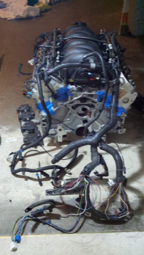
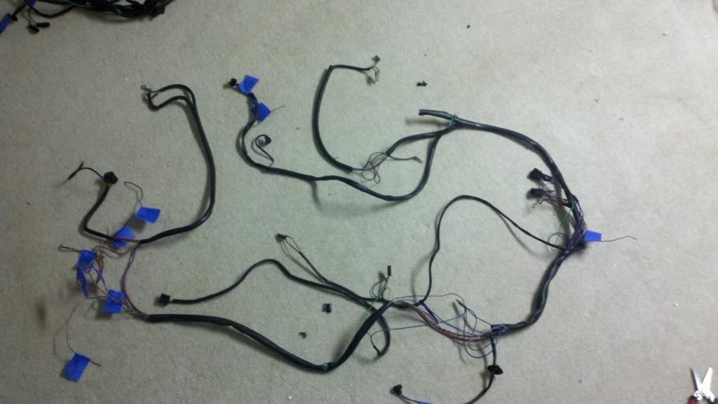
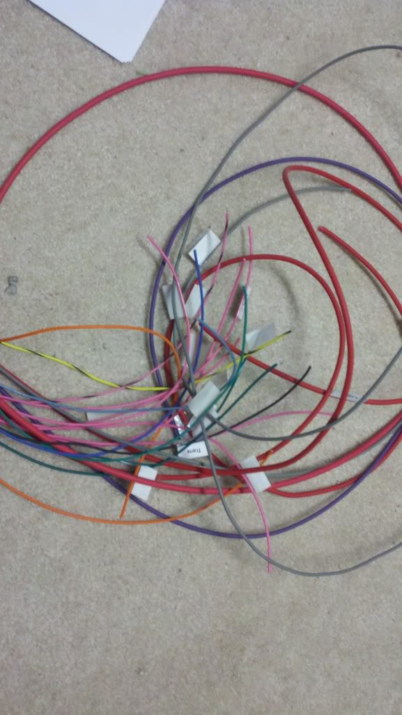
I got a bit more work done today on the wiring harness. I pulled apart the stock LS1 harness and removed everything that I wouldn't be using. I will also be replacing the stock loom warp with some aftermarket warp that looks a lot better. Here is what I started with
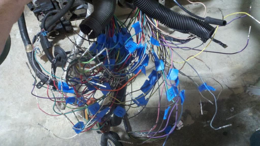
Labeling all the pcm wires
Pile of stuff I pulled out
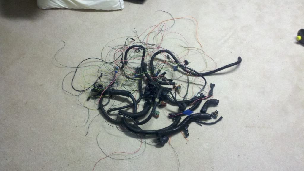
after pulling out all the unnecessary stuff
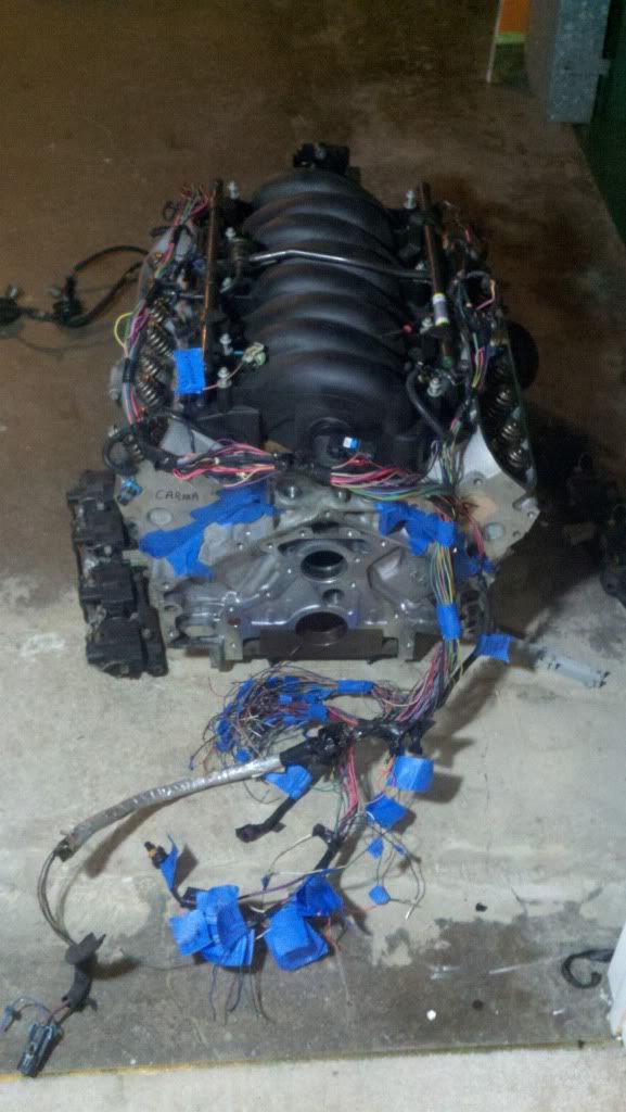
I ordered a relay and fuse box which should be here on monday. Once I get that in, I can splice the 190e and ls1 harness together.
Labeling all the pcm wires
Pile of stuff I pulled out
after pulling out all the unnecessary stuff
I ordered a relay and fuse box which should be here on monday. Once I get that in, I can splice the 190e and ls1 harness together.
12-19-2011, 11:47 PM
#44
On The Tree
Thread Starter
iTrader: (2)
Join Date: Mar 2008
Location: Nashvegas
Posts: 136
Likes: 0
Received 0 Likes
on
0 Posts
Got some more done on the wiring today. I stripped down the 190 harness and labeled everything that I will need to reconnect later. I eliminated the fuel pump relay, ac relay, and aux fan relay from this harness. Now this harness only has the Over Voltage protection relay, AC hook up, washer sprayer heaters, a couple of fuse blocks, the starter wire, coolant gauge temp input and tach power. I still need to figure out how I am going to wire the AC and if the GM tach output and coolant temp scaling will work with the factory 190 gauges.
I also bought this fuse/relay box from Current Performance Racing. It was $95 and comes with AC relay, Fuel pump relay, Ignition Relay (switched 12v power), Starter relay(which I won't be using), and fan relays. It also has fuses for the LS1 Pcm, fans, ac, coil packs, etc. It also comes with labeled pigtails and a really nice wiring diagram and pin out explanation. It's a pretty nice nice and I am very pleased with it. This is definitely a must buy if you want to do this swap.
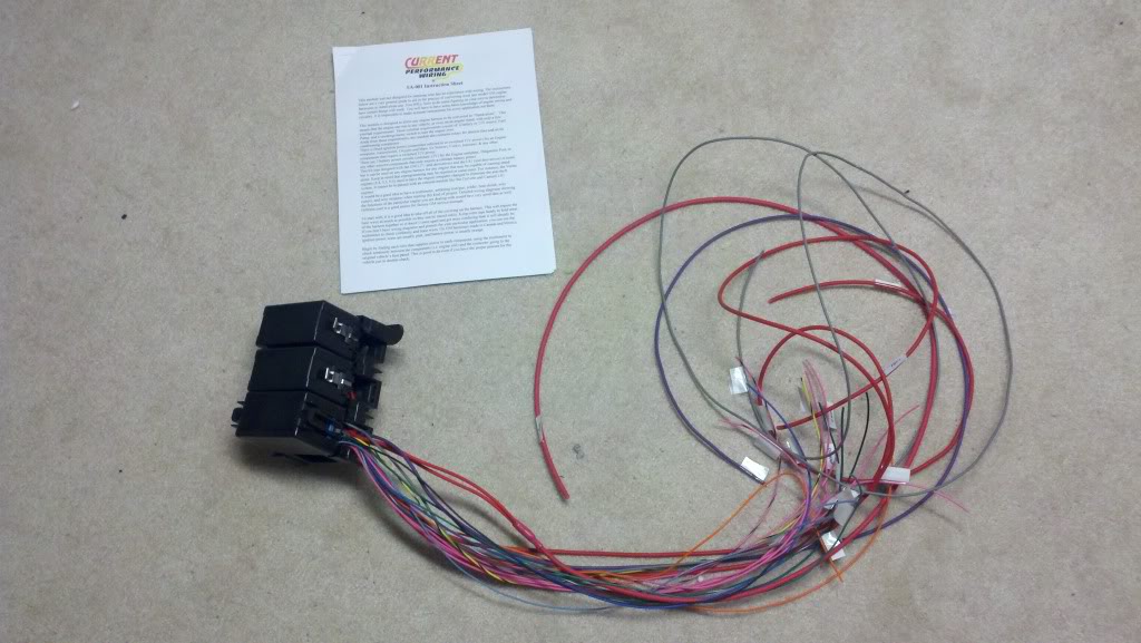
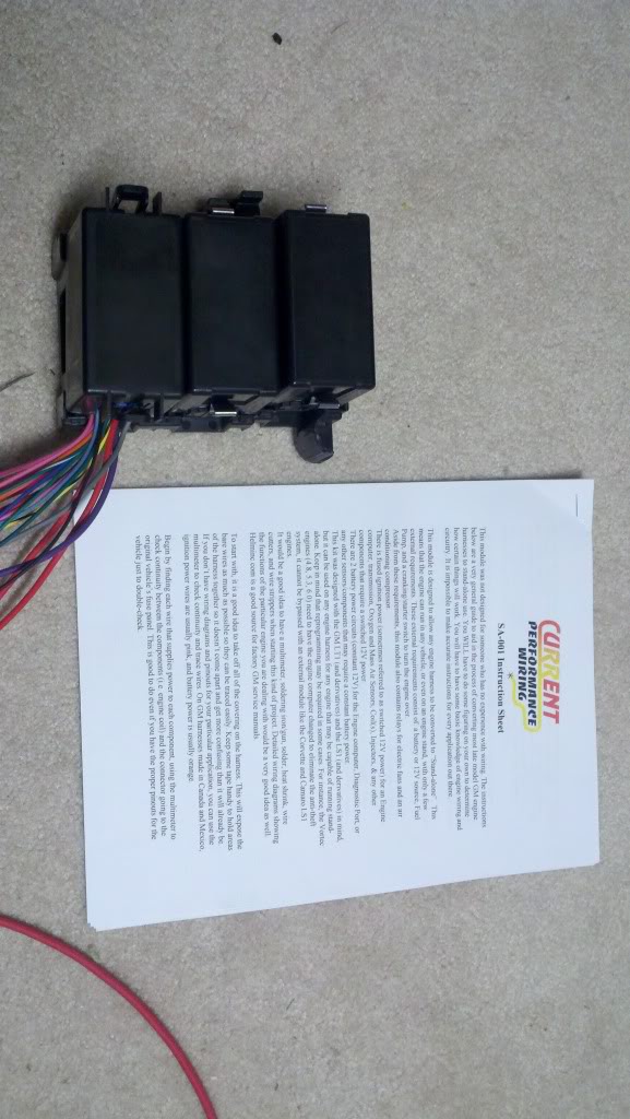
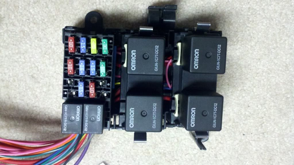
I will hopefully be looming the harness over the next couple of days before I go home for the holidays.
I also bought this fuse/relay box from Current Performance Racing. It was $95 and comes with AC relay, Fuel pump relay, Ignition Relay (switched 12v power), Starter relay(which I won't be using), and fan relays. It also has fuses for the LS1 Pcm, fans, ac, coil packs, etc. It also comes with labeled pigtails and a really nice wiring diagram and pin out explanation. It's a pretty nice nice and I am very pleased with it. This is definitely a must buy if you want to do this swap.
I will hopefully be looming the harness over the next couple of days before I go home for the holidays.
12-20-2011, 06:51 PM
#46
On The Tree
Thread Starter
iTrader: (2)
Join Date: Mar 2008
Location: Nashvegas
Posts: 136
Likes: 0
Received 0 Likes
on
0 Posts
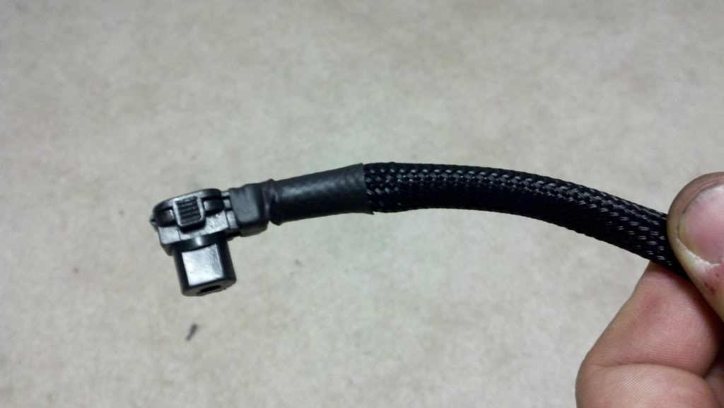
Got some heat shrink and a sample of the split wire loom today. I wanted to see what it would look like so I dressed up the oem 190e starter wire. Came out pretty good. The heat shrink keep sliding off the connector though. I know that they make heat shrink with glue in it. I am thinking about buying some. Anyone else got any other suggestions?
12-20-2011, 08:04 PM
#47

Use a small cable tie wrap on it before you slide the heat shrink over it. One like this.
http://www.mouser.com/ProductDetail/...osKRjZKlY60%3d
These are very small and will keep it all together.
http://www.mouser.com/ProductDetail/...osKRjZKlY60%3d
These are very small and will keep it all together.
12-21-2011, 11:59 PM
#48
On The Tree
Thread Starter
iTrader: (2)
Join Date: Mar 2008
Location: Nashvegas
Posts: 136
Likes: 0
Received 0 Likes
on
0 Posts
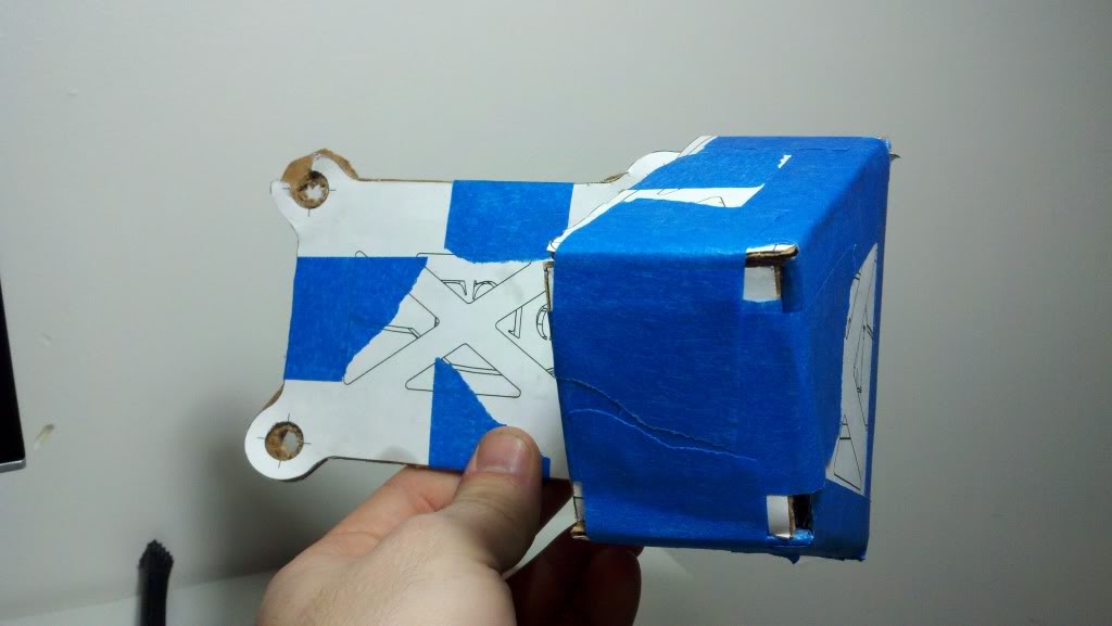
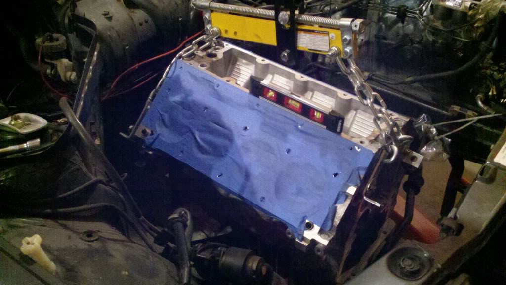
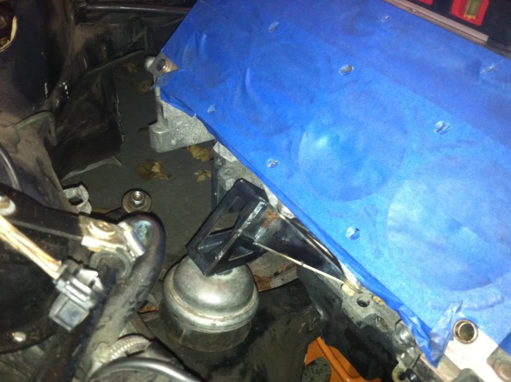
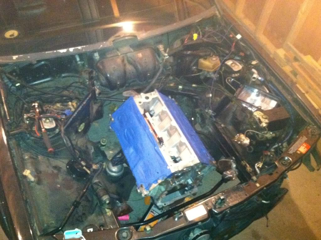
I put the engine in the engine bay today to see if the cardboard mock up of the engine mount that I made would fit.
After getting the engine in the car, I realized that I can probably get away with reusing the stock motor mount and making a mount that just bolts to the top of it. I figure if the turbo guys can make about the same amount of power that I will be making on the stock mounts then I should be fine. Plus the motors weight about the same, so I am not too worried about it. Plus, if all else fails, I will just buy a poly mount and call it good.
Here is the LS in the bay.
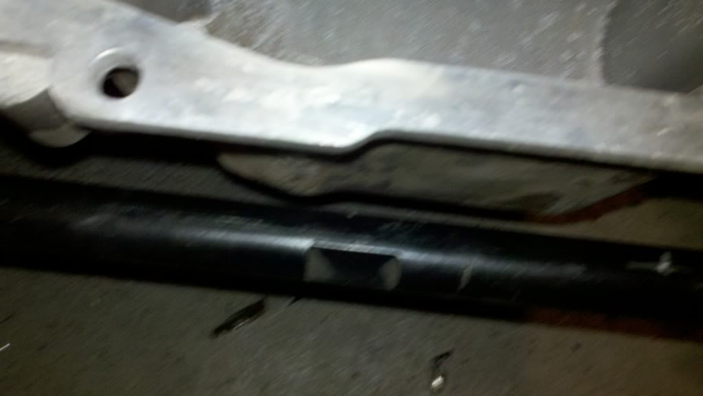
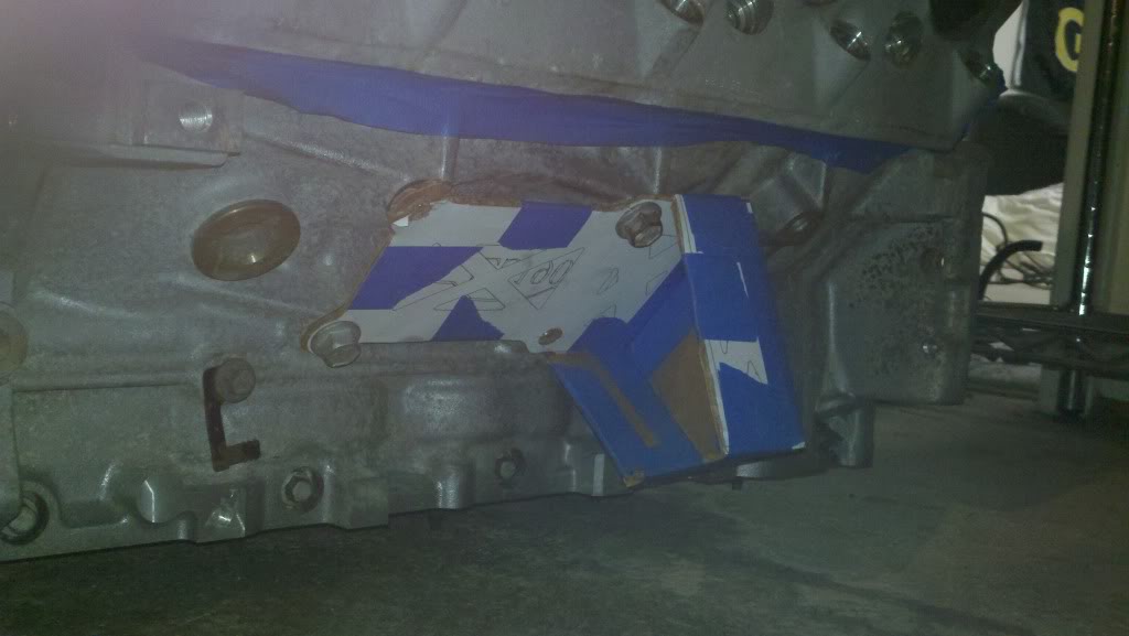
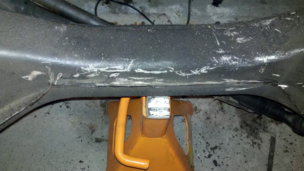
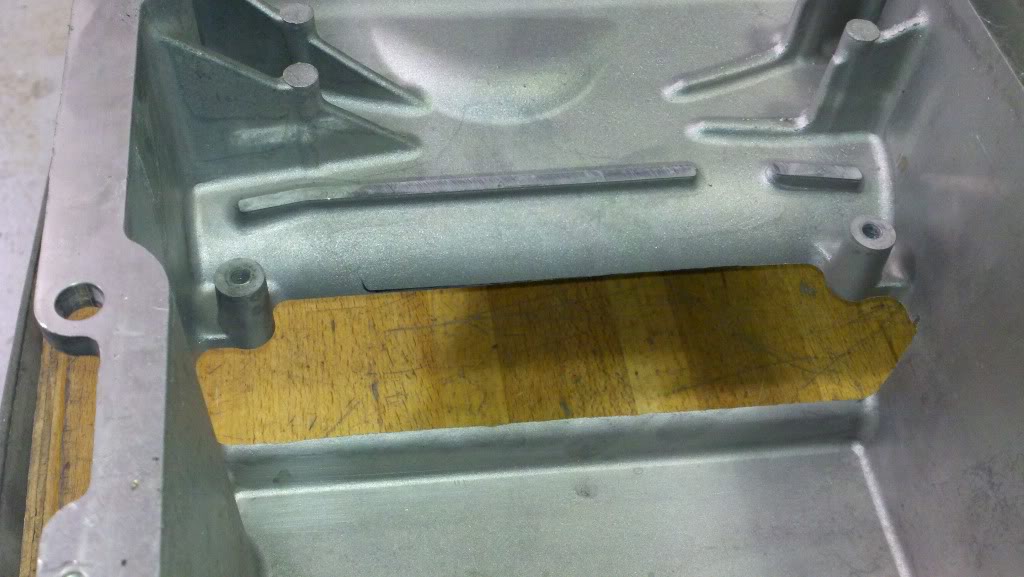
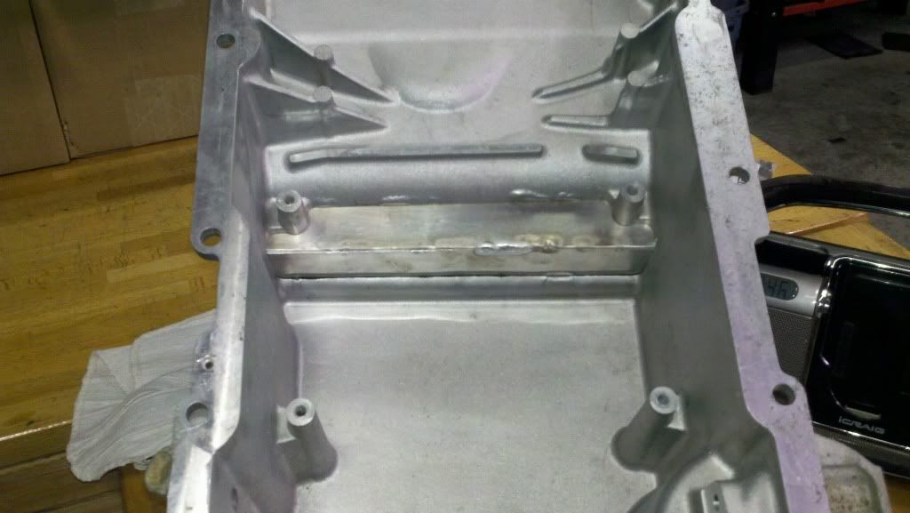
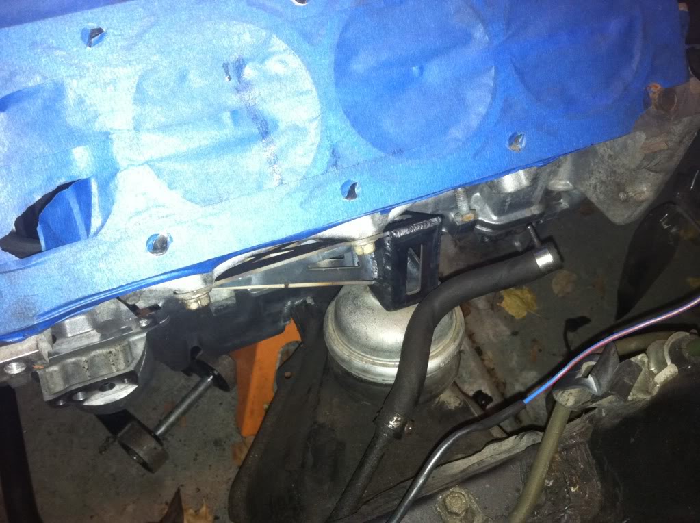
The GTO oil pan barely hit on the subframe. So, to make it clear, I cut the pinch weld off of the subframe and I put about a 1" by 1" notch in the pan.
Modified subframe (I will go back and clean it up and paint it once everything gets finalized.):
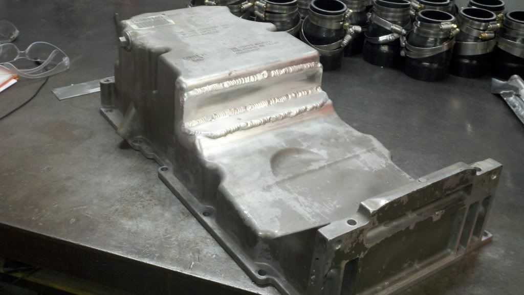
Modified Oil Pan (don't make fun of my welds. I am still learning.)
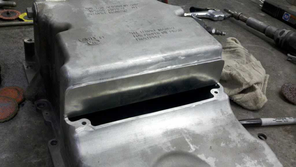
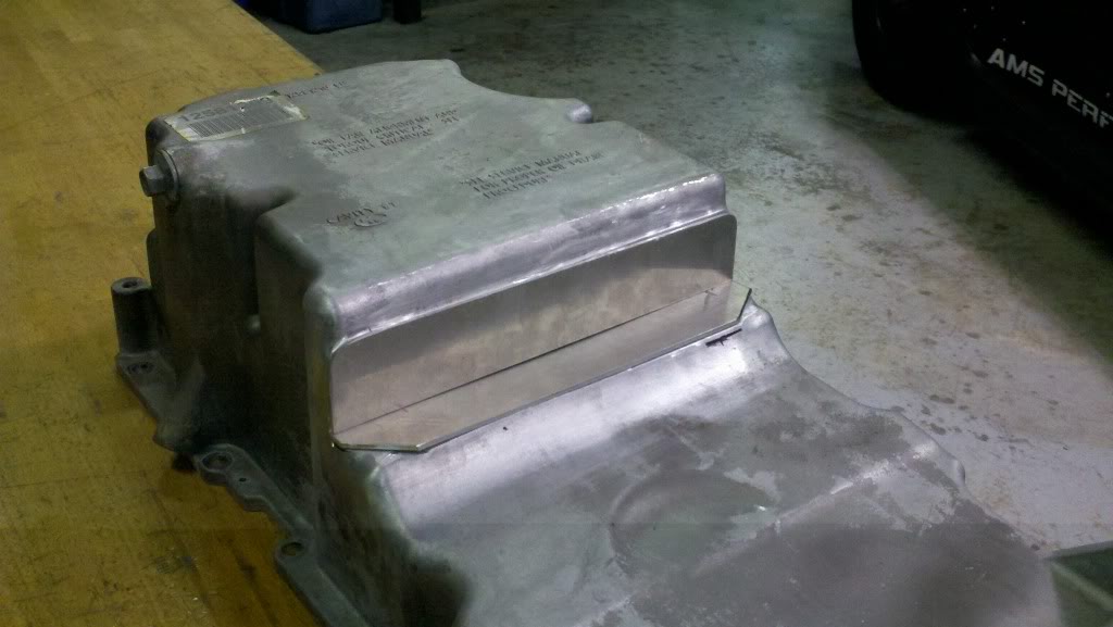
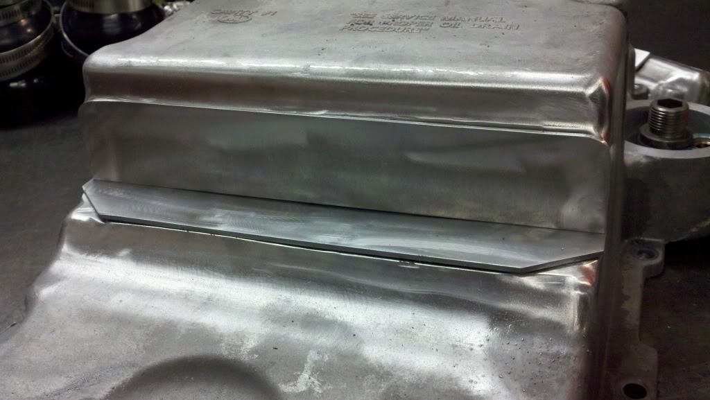
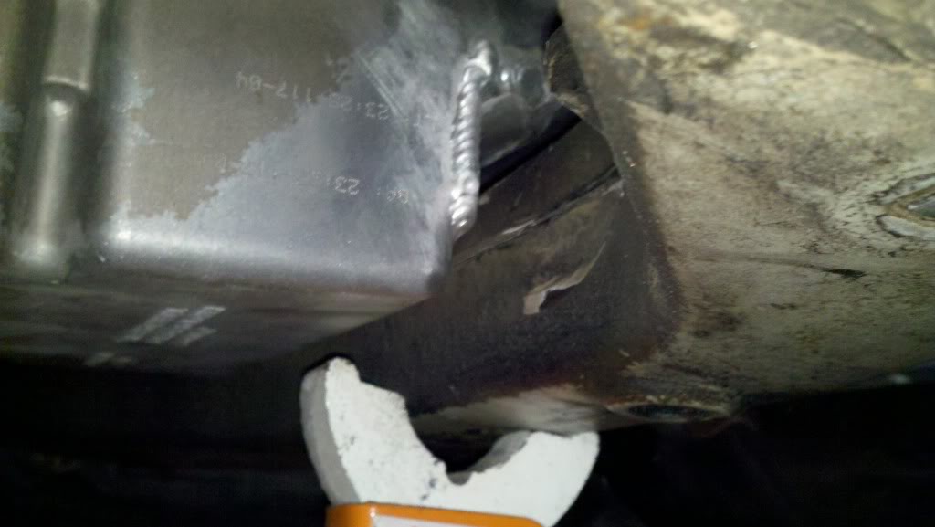
How the pan clears with the modified pan and subframe:
I also did some measuring and figured out that the shifter hole is ~32" from the back of the engine. Turns our a GTO shifter sits ~32" from the front of a T-56. I will be buying a stock GTO shifter over Christmas break.
Here is a pic of the modified engine mount:
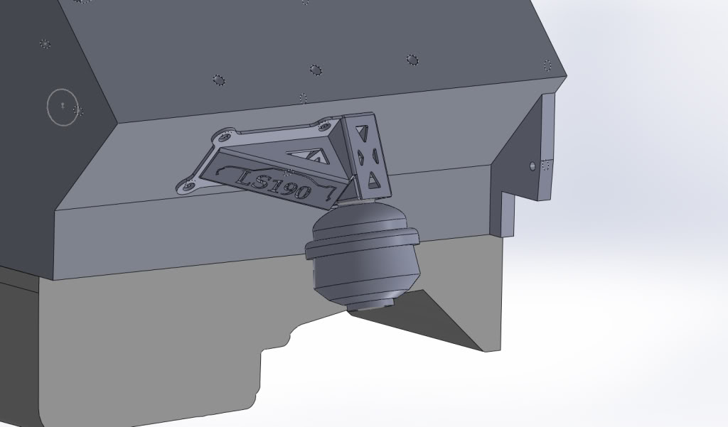
After getting the engine in the car, I realized that I can probably get away with reusing the stock motor mount and making a mount that just bolts to the top of it. I figure if the turbo guys can make about the same amount of power that I will be making on the stock mounts then I should be fine. Plus the motors weight about the same, so I am not too worried about it. Plus, if all else fails, I will just buy a poly mount and call it good.
Here is the LS in the bay.
The GTO oil pan barely hit on the subframe. So, to make it clear, I cut the pinch weld off of the subframe and I put about a 1" by 1" notch in the pan.
Modified subframe (I will go back and clean it up and paint it once everything gets finalized.):
Modified Oil Pan (don't make fun of my welds. I am still learning.)
How the pan clears with the modified pan and subframe:
I also did some measuring and figured out that the shifter hole is ~32" from the back of the engine. Turns our a GTO shifter sits ~32" from the front of a T-56. I will be buying a stock GTO shifter over Christmas break.
Here is a pic of the modified engine mount:
Last edited by clainhart3; 12-22-2011 at 12:09 AM.
01-09-2012, 10:55 PM
#50
On The Tree
Thread Starter
iTrader: (2)
Join Date: Mar 2008
Location: Nashvegas
Posts: 136
Likes: 0
Received 0 Likes
on
0 Posts
So I test fit the mock-up mounts on the car and they fit perfectly. I went ahead and did some FEA on the mounts and here are my results.
Passenger side:
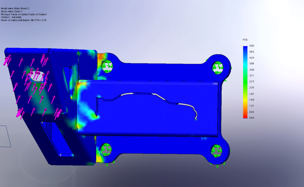
This mount will see the most force since the motor rotates clockwise when looking from the front of the car. This is with 900lbs of force acting on the mount face. This simulates half of the motor weight (~600lbs) plus the full force of the torque (~350 ft-lbs @ 7.5") on the mount. As you can see it shows a min factor of safety of .45. This occurred on a sharp corner of one of the tabs. This is a false reading of the software. There was a FOS of ~1 right next to the upper left hand mount hole. I will be re-enforcing this area with extra welds and possibly more material. Every where else showed a FOS of over 5. Therefore I am not too worried about these mounts failing.
Drivers side:
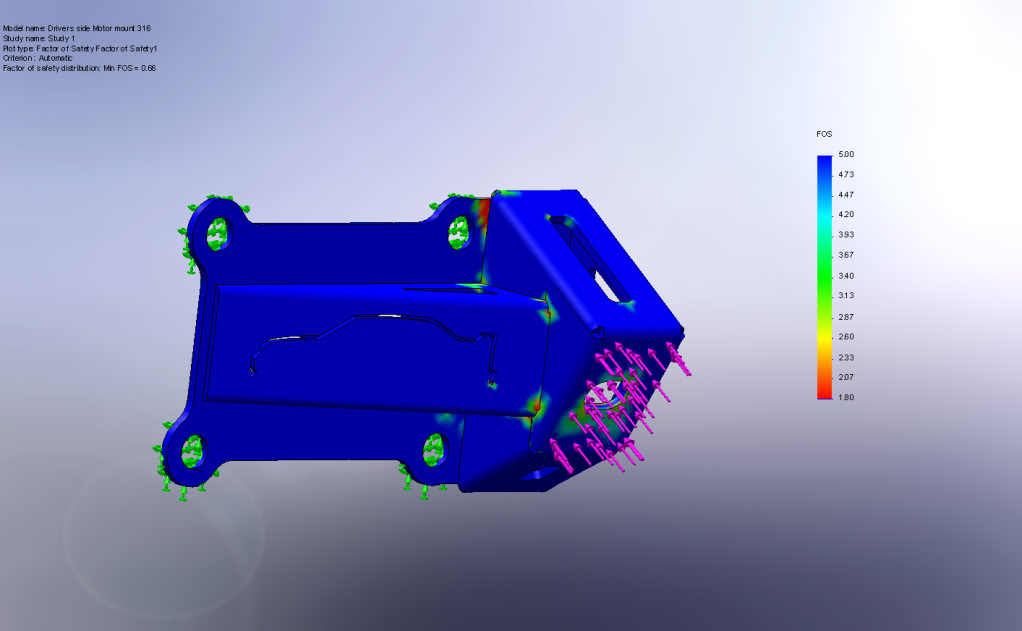
This mount was subjected to the same forces. This mount saw a min FOS ~1.8 that wasn't caused by a sharp corner (stress concentration) with most of the mount seeing a FOS >5. Again the area around the upper right and mounting hole will be re-enforced with extra welding and possibly more material.
I sent in the drawings today to have them water jet cut. I should have them by Wednesday. I should have the motor in the car by the end of the weekend.
Passenger side:
This mount will see the most force since the motor rotates clockwise when looking from the front of the car. This is with 900lbs of force acting on the mount face. This simulates half of the motor weight (~600lbs) plus the full force of the torque (~350 ft-lbs @ 7.5") on the mount. As you can see it shows a min factor of safety of .45. This occurred on a sharp corner of one of the tabs. This is a false reading of the software. There was a FOS of ~1 right next to the upper left hand mount hole. I will be re-enforcing this area with extra welds and possibly more material. Every where else showed a FOS of over 5. Therefore I am not too worried about these mounts failing.
Drivers side:
This mount was subjected to the same forces. This mount saw a min FOS ~1.8 that wasn't caused by a sharp corner (stress concentration) with most of the mount seeing a FOS >5. Again the area around the upper right and mounting hole will be re-enforced with extra welding and possibly more material.
I sent in the drawings today to have them water jet cut. I should have them by Wednesday. I should have the motor in the car by the end of the weekend.
01-11-2012, 08:04 AM
#53
On The Tree
Thread Starter
iTrader: (2)
Join Date: Mar 2008
Location: Nashvegas
Posts: 136
Likes: 0
Received 0 Likes
on
0 Posts
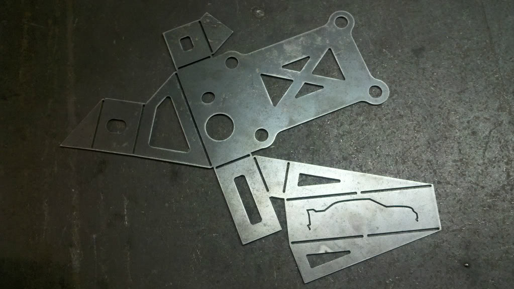
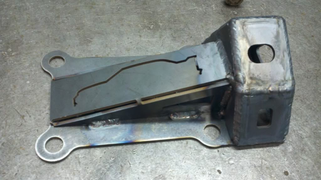
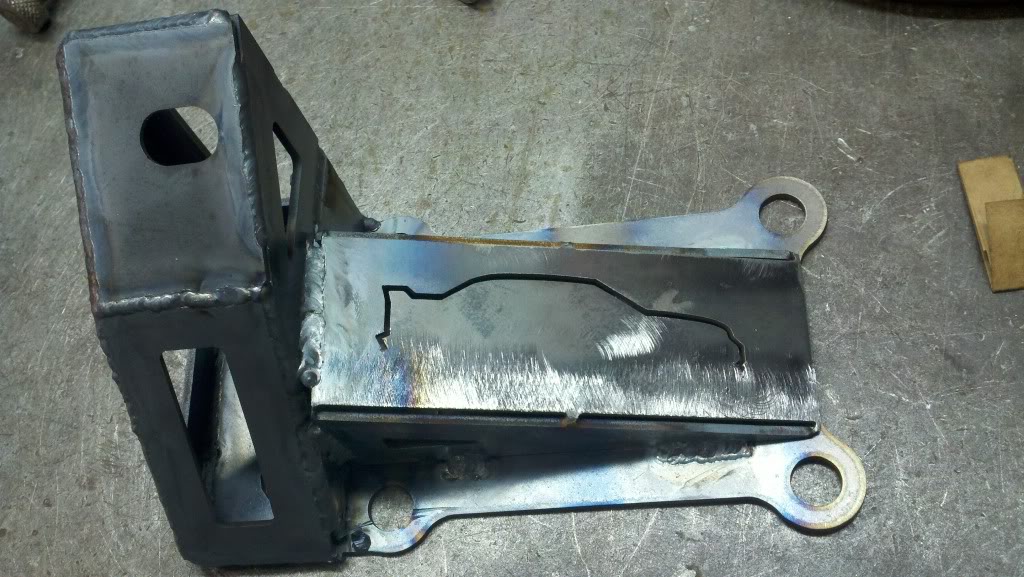
So I got the mounts in today. There were a couple small issues with the parts, so I will probably have to have them re-made. Not a huge deal. I will be using these to test fit the motor though. Here is the driver's side mount before bending.
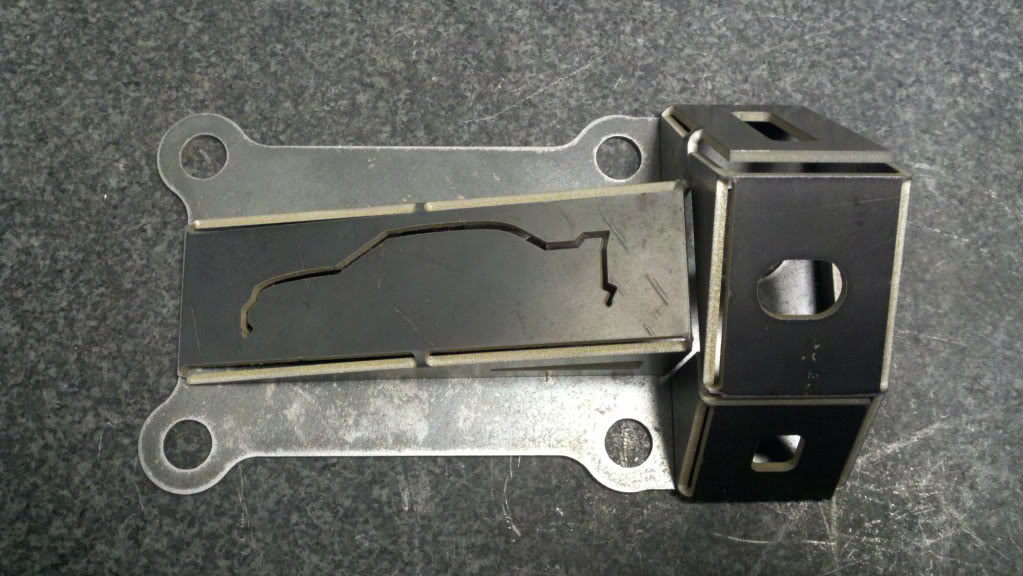
and here it is all bent up. I will weld this one up today along with the passenger side mount. I hope to drop the motor in the car tonight. The low tonight is 30, so my garage is will cold as ****, but I think it will be worth bearing the cold to see the motor in the car for the first time.
Once I have the motor in the car, I will be able to finish all the wiring with the correct lengths and everything. After that is done, I will need to figure out a steering solution. I am still trying to find a good source for information about the dos and don'ts of modifying a steering system. I know how to calculate all the steering angles and everything, I just want to know if there is anything that I need to avoid/watch out for. Let me know if anyone has any good places to look for that kind of information. Thanks
01-11-2012, 10:13 PM
#54
On The Tree
Thread Starter
iTrader: (2)
Join Date: Mar 2008
Location: Nashvegas
Posts: 136
Likes: 0
Received 0 Likes
on
0 Posts
I will check out some of those companies for a rack. I hope that I can find a stock rack that will work. If anyone happens to know of a rack that measures ~19" between the inner ball joints, please let me know.
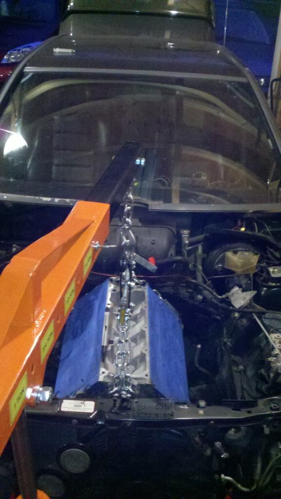
I got the mounts welded up today. I decided just throw them together real quick and use them to help me mock everything up, so don't give me too much **** about the shitty welds. I know they are garbage. I have already decided to cut another set of mounts cut, so no reason to make those look really nice. Here are some pics
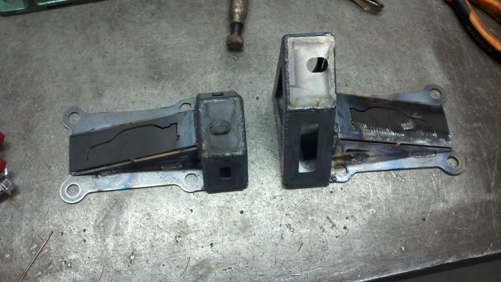
And on the motor.
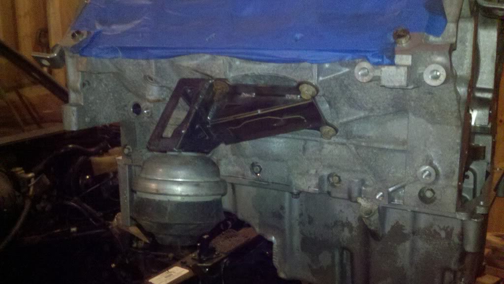
And finally in the car.
After setting the motor in the car, I realized that the stock bushings are way too soft. I think that I will end up buying some poly mounts from Ake.
I got the mounts welded up today. I decided just throw them together real quick and use them to help me mock everything up, so don't give me too much **** about the shitty welds. I know they are garbage. I have already decided to cut another set of mounts cut, so no reason to make those look really nice. Here are some pics
And on the motor.
And finally in the car.
After setting the motor in the car, I realized that the stock bushings are way too soft. I think that I will end up buying some poly mounts from Ake.
01-12-2012, 01:27 AM
#55
I got the mounts welded up today. I decided just throw them together real quick and use them to help me mock everything up, so don't give me too much **** about the shitty welds. I know they are garbage. I have already decided to cut another set of mounts cut, so no reason to make those look really nice.
 J/K Honestly they actually aren't terrible. I have seen people calling themselves fabricators and selling their work who can't do as well. You will improve with time because nothing teaches like experience.
 I like what you have done on the engine mounts, that is a pretty clean idea. I think you will be much happier with poly engine mounts too.
 01-19-2012, 08:10 PM
#57
On The Tree
Thread Starter
iTrader: (2)
Join Date: Mar 2008
Location: Nashvegas
Posts: 136
Likes: 0
Received 0 Likes
on
0 Posts
Kag - I might do a EVO I kit in the future, but that will probably be a while from now. I also plan on getting some new wheels at some point. Maybe CCW classics?
Not much of an update, but I got all the loom wrap and heat shrink for my harness.
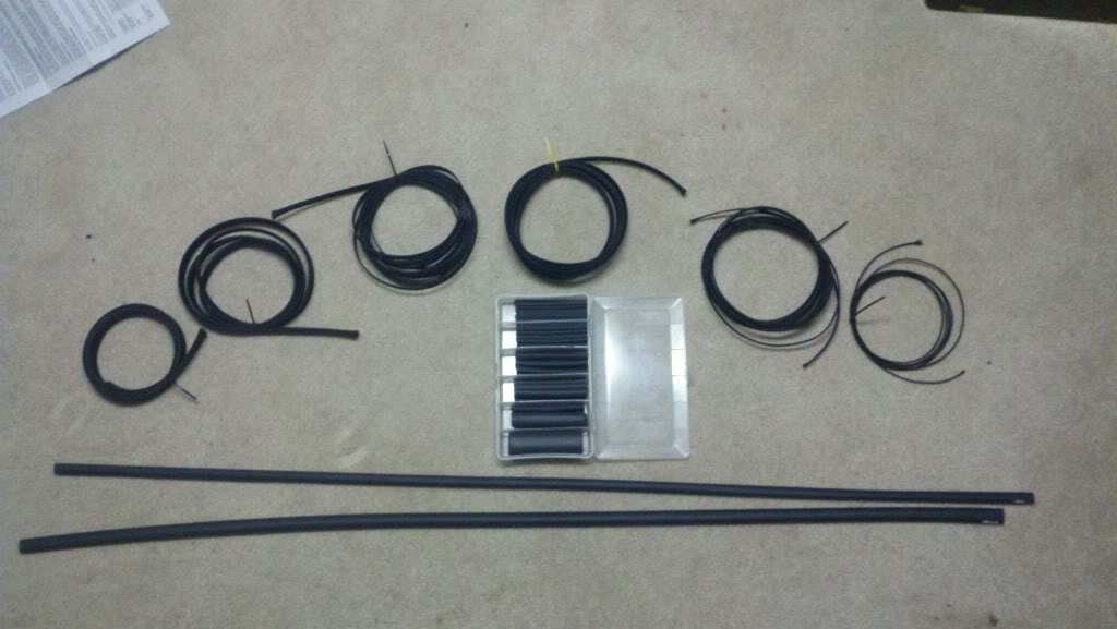
Only cost about $80. I used buyheatshrink.com for the adhesive lined shrink wrap and cabletiesandmore.com for the loom wrap. We are supposed to get 6" of snow this weekend and have temps around 0�, but I still hope to get some of the harness done. I will probably be investing in a space heater.
I also got my valve covers and front and rear covers off my motor back from the powder coater. They came out really nice. I had them done in wrinkle black. I will post a picture tomorrow. I also will have the oil pan, water pump, and possibly the alternator coated as well. Should look pretty nice.
Not much of an update, but I got all the loom wrap and heat shrink for my harness.
Only cost about $80. I used buyheatshrink.com for the adhesive lined shrink wrap and cabletiesandmore.com for the loom wrap. We are supposed to get 6" of snow this weekend and have temps around 0�, but I still hope to get some of the harness done. I will probably be investing in a space heater.
I also got my valve covers and front and rear covers off my motor back from the powder coater. They came out really nice. I had them done in wrinkle black. I will post a picture tomorrow. I also will have the oil pan, water pump, and possibly the alternator coated as well. Should look pretty nice.
01-19-2012, 08:29 PM
#58
12 Second Club
iTrader: (26)
Join Date: Apr 2005
Location: Brockport NY
Posts: 1,456
Likes: 0
Received 0 Likes
on
0 Posts
This is very cool I have been tossing this idea for a long time. I am a tech at a Mercedes dealer if you think of anything you need on the Mercedes side of things feel free to shoot me a p.m and i will try and get any info i can to you.
01-27-2012, 07:57 AM
#59
On The Tree
Thread Starter
iTrader: (2)
Join Date: Mar 2008
Location: Nashvegas
Posts: 136
Likes: 0
Received 0 Likes
on
0 Posts
Small update:
I have been working on the harness a little bit for the past couple nights. It is taking a but longer than I thought, but I'm taking my time and making sure I do everything right. Here is a picture of what all the connectors will look like when I am done.
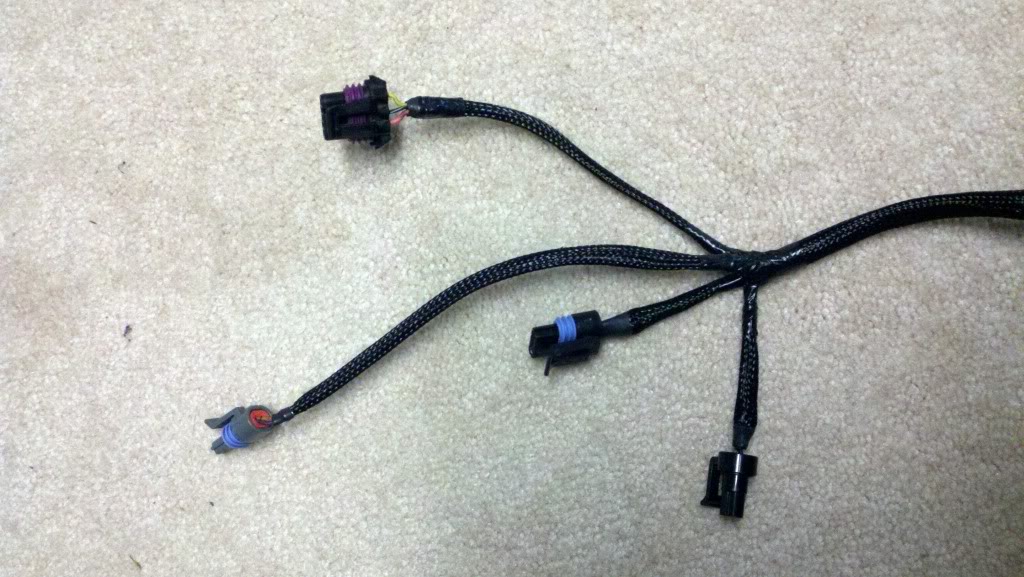
Here are the two ECU connectors. I'm not finished cleaning up this end of the harness. The large grey connector to the left is a GM connector I stole off the body harness I had. It will go to the fuse and relay box I bought.
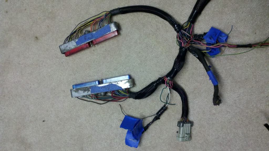
I still need to figure out the lengths of a couple of wires like the tach signal, switched power, O2 sensor, and a few other things, and then I can finish up this end of the harness.
I will work on mounting the ECU and fuse and relay box this weekend.
I have been working on the harness a little bit for the past couple nights. It is taking a but longer than I thought, but I'm taking my time and making sure I do everything right. Here is a picture of what all the connectors will look like when I am done.
Here are the two ECU connectors. I'm not finished cleaning up this end of the harness. The large grey connector to the left is a GM connector I stole off the body harness I had. It will go to the fuse and relay box I bought.
I still need to figure out the lengths of a couple of wires like the tach signal, switched power, O2 sensor, and a few other things, and then I can finish up this end of the harness.
I will work on mounting the ECU and fuse and relay box this weekend.
01-27-2012, 02:55 PM
#60
On The Tree
iTrader: (28)
Join Date: Jun 2010
Location: New Phila, OH
Posts: 129
Likes: 0
Received 0 Likes
on
0 Posts
Great looking swap. Your harness is looking good. What sizes of wrap did you buy to cover the harness? I have been looking around for something exactly like this.