
Fan wiring help
 02-05-2012, 11:46 PM
#1
Launching!
Thread Starter

Join Date: Jun 2011
Location: Walnut Creek, ca
Posts: 244
Likes: 0
Received 0 Likes
on
0 Posts

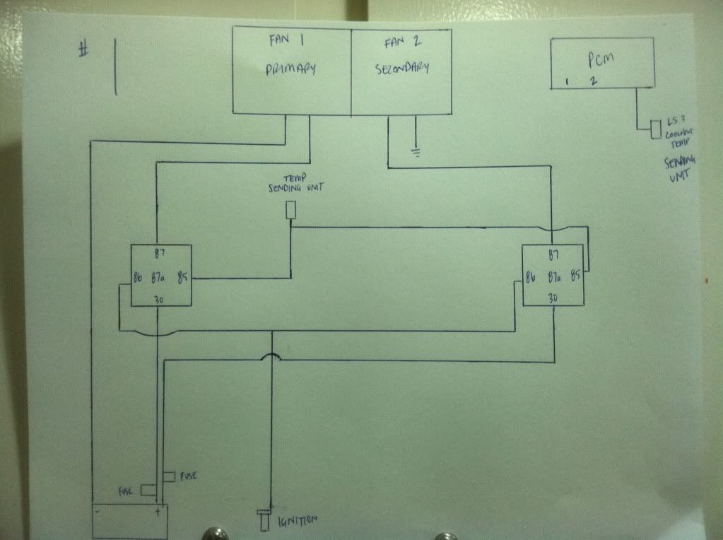
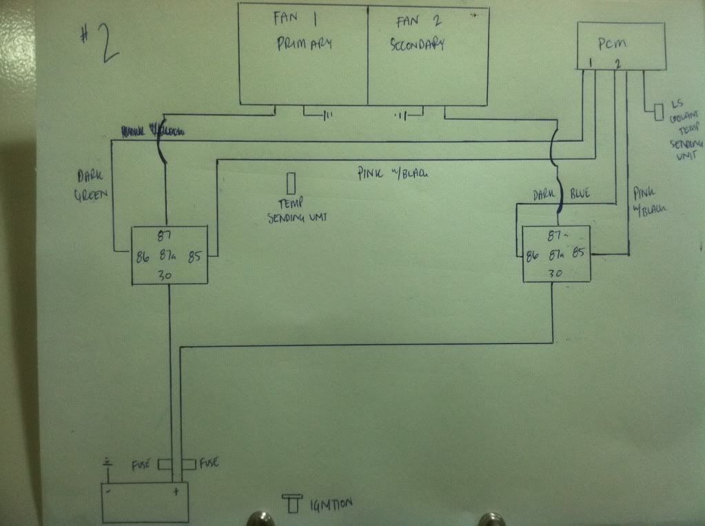
I need help with wiring my fans. Picture #1 is how the wiring is if I have a standard SBC. Picture #2 is how I think it should be wired now that I have a LS3/computer. Let me know what you guys thinn! thanks
 02-06-2012, 12:03 AM
#2
TECH Apprentice

Join Date: Jul 2011
Posts: 393
Likes: 0
Received 0 Likes
on
0 Posts
On mine I only have a single fan but its not done like that. Mine is done as follows.
The PCM is only completing the "ground" to the relay pin 85. Pin 86 gets 12v from the ignition being switched on. My fan doesn't run when I turn off the ignition but then again I really wouldn't want it to simply because of the drain on the battery. Pins 30, and 87 are the same as mine.
The PCM is only completing the "ground" to the relay pin 85. Pin 86 gets 12v from the ignition being switched on. My fan doesn't run when I turn off the ignition but then again I really wouldn't want it to simply because of the drain on the battery. Pins 30, and 87 are the same as mine.
02-07-2012, 07:52 PM
#3
Launching!
Thread Starter
Join Date: Jun 2011
Location: Walnut Creek, ca
Posts: 244
Likes: 0
Received 0 Likes
on
0 Posts
On the paper from Speartech it says that the pink w/black wire is 12v key on to pin 85. the dark blue and dark green are ECM ground control to pin 86. That would be opposite from what you have described?
02-07-2012, 08:03 PM
#4
TECH Fanatic
I am using a '03 truck PCM and it has no fan control cucuit. I am going to use a universal thermostat with a probe that goes into the radiator fins to control the fans. They have a small screw to adjust the temp.
Trending Topics
02-07-2012, 09:29 PM
#8
On my Chevelle. I used a standalone system that is not linked or wired into the PCM. I used two SPAL fans and there standalone controller. I can set the two temp to come on for low and high speed on the fly. I was able to use the 99 temp sender on the driver side head to input into the SPAL PWM controller. Has worked well for over 5 years.
Just another option.
Just another option.
02-07-2012, 10:23 PM
#9
TECH Apprentice
Join Date: Jul 2011
Posts: 393
Likes: 0
Received 0 Likes
on
0 Posts
You are correct mine is 85 12v, 86 ground. It was late and I guess I wasn't thinking straight.
02-08-2012, 10:54 AM
#12

I'm not familiar with the LS3 PCM switching, but by your scematic it looks the same as my LS1. The stock LS1 switching scheme runs two fans in series (so each fan sees 6V) for low speed, then switches to parallel (so each fan sees 12V) for high speed.
Andys