
88 Fiero Formula LS4/F40 6 speed swap
 11-12-2012, 04:41 PM
#61


Good looking swap. Love the attention to detail on the wiring aspect
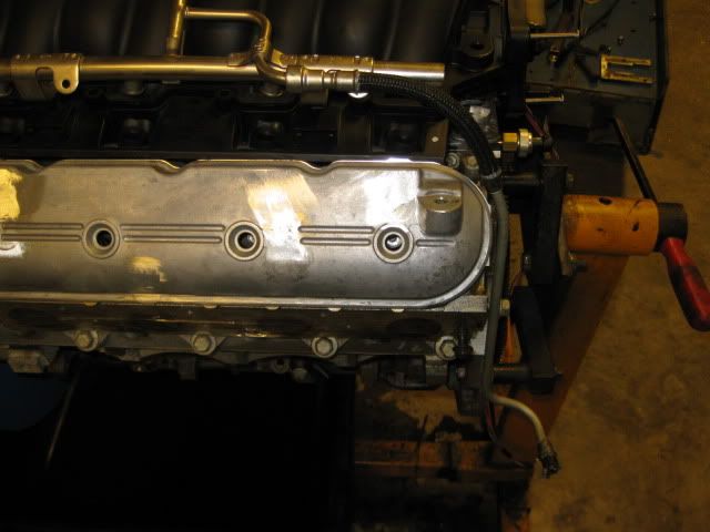
How much trouble is it to pull the valve cover with the super long PCV tube?
Wouldnt it be beneficial to mount some sort of bulkhead connector on the firewall since the C500 was removed? Much easier when pulling the engine to unhook one bulkhead than strip all of the harness from the engine
How much trouble is it to pull the valve cover with the super long PCV tube?
Wouldnt it be beneficial to mount some sort of bulkhead connector on the firewall since the C500 was removed? Much easier when pulling the engine to unhook one bulkhead than strip all of the harness from the engine

 11-13-2012, 05:33 AM
#63

Good looking swap. Love the attention to detail on the wiring aspect
How much trouble is it to pull the valve cover with the super long PCV tube?
Wouldnt it be beneficial to mount some sort of bulkhead connector on the firewall since the C500 was removed? Much easier when pulling the engine to unhook one bulkhead than strip all of the harness from the engine
How much trouble is it to pull the valve cover with the super long PCV tube?
Wouldnt it be beneficial to mount some sort of bulkhead connector on the firewall since the C500 was removed? Much easier when pulling the engine to unhook one bulkhead than strip all of the harness from the engine
Removing the valve cover isn't bad, just undo the 4 bolts and pull it up and back to snake the PCV hard line past the harness/hoses by the throttle body.
I had kicked around the idea of a 2 part pass through harness, but haven't committed to it yet. I need to finish the harness to know exactly how many wires will have to make it through the connector and how many will be a larger gauge terminal. The harness as I have it planned will still be able to separate in the console area so the harness can be pulled back through the firewall to the engine and drop everything with the engine.
 11-16-2012, 04:17 PM
#66
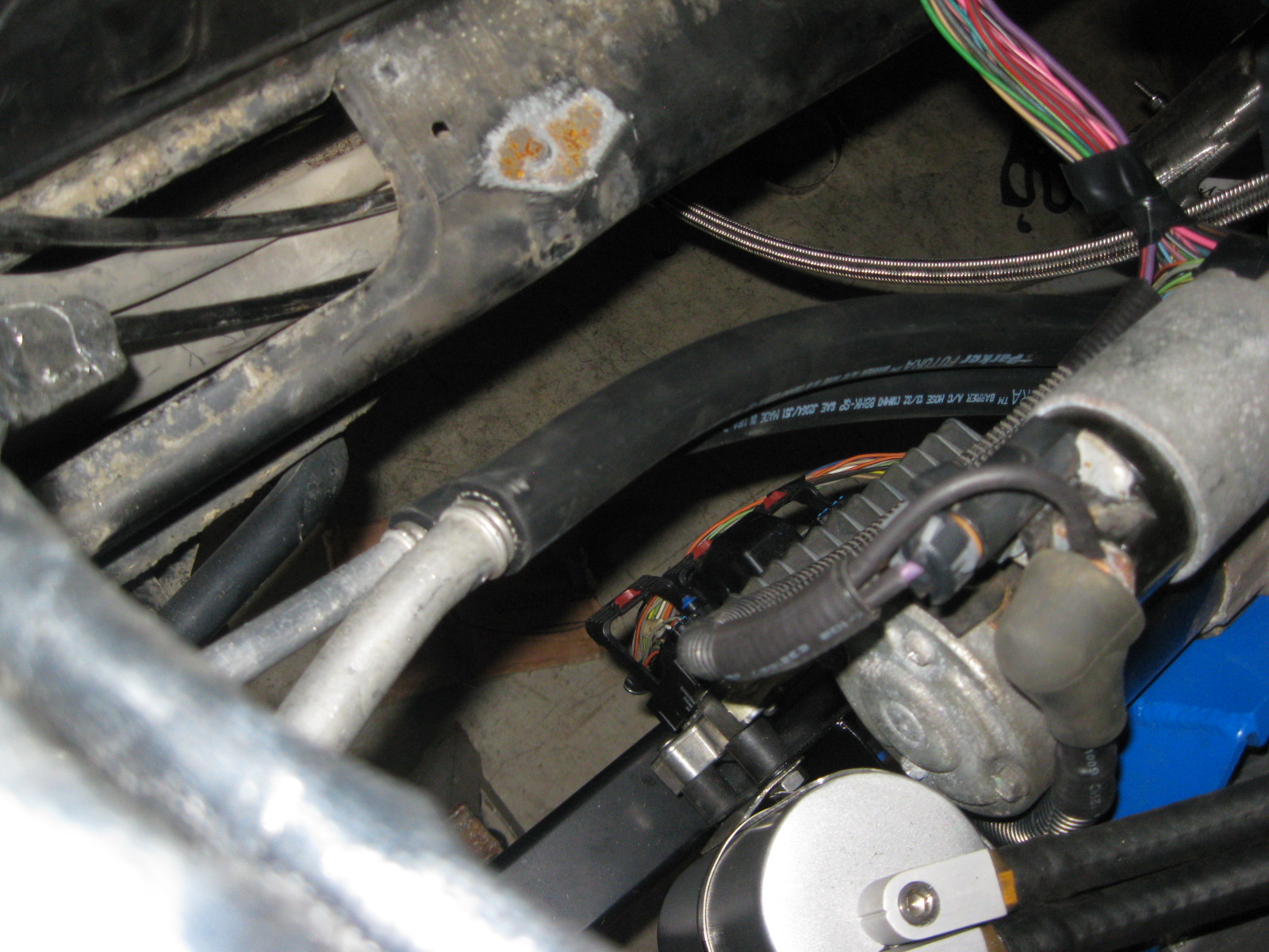
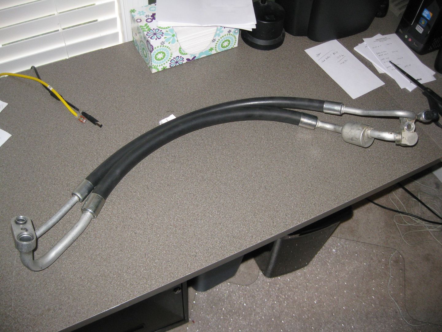
Been working on the AC lines...
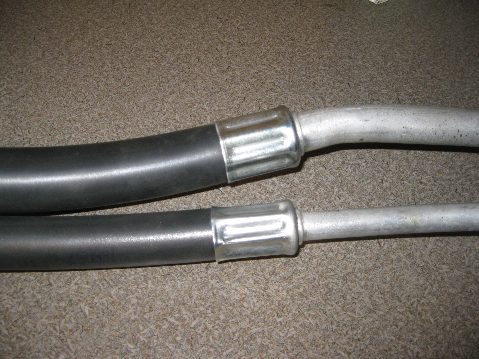
I used a cut off wheel to remove the oem crimped hose clamps from the LS4 compressor end as well as the Fiero chassis aluminum hose ends. Then It was a matter of cutting the new A/C barrier hose to the proper length. Here are some pictures of the test fit:
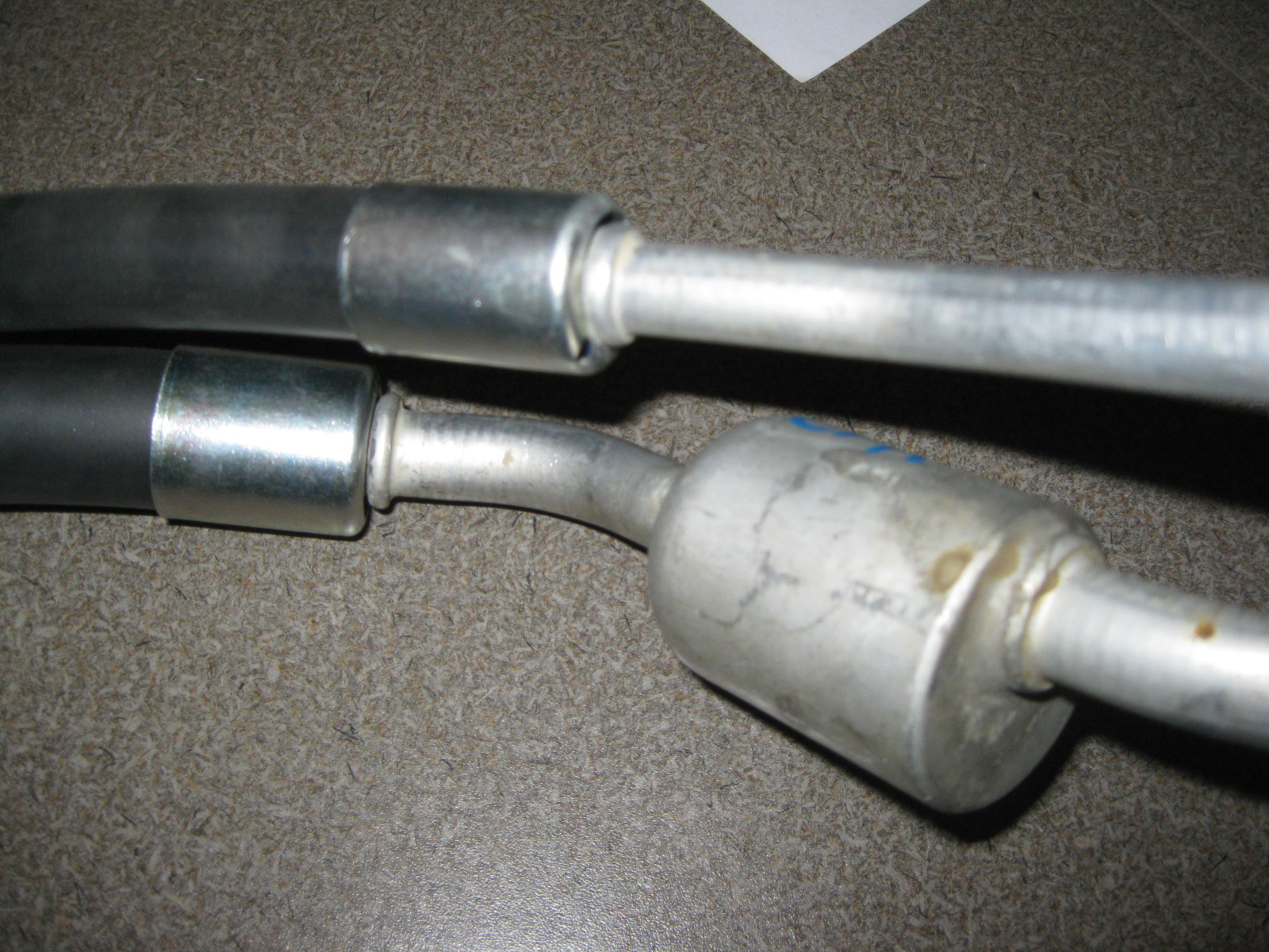
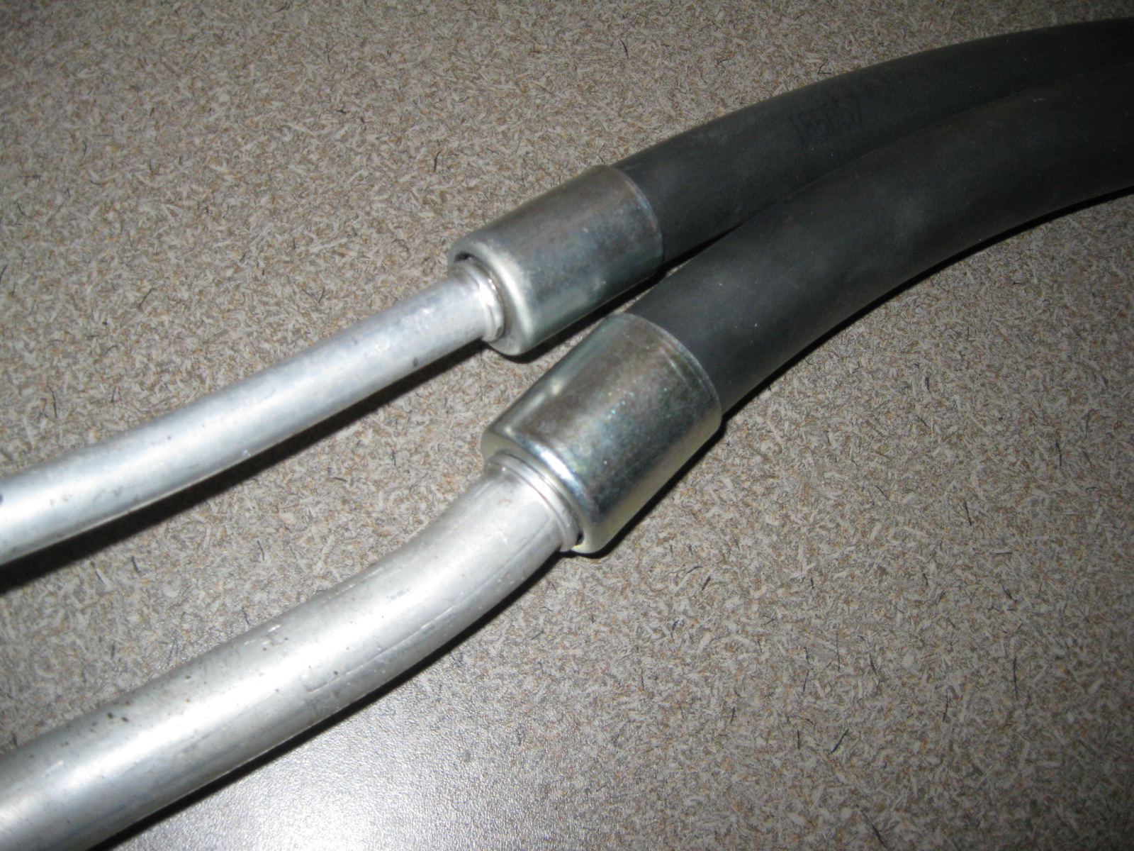
While searching for the ferrules for the ends I came across several types for the OEM bead lock (the ferrule is locked between two beads on the fitting) fittings. Most of them required a larrger hole in the ferrule so you could push the ferrule past the beads and use a c-clip to retain it. I am sure those would work, but I also found some that had the larger hole offset:
http://www.mobileacproducts.com/ferrules.asp
So these just slide into place, fit in-between the beads, then when centered by the hose they are locked into place. Pretty slick setup, so that is what I am going with. You can buy the ferrules in packs of 25 for each size and they come to about $1 per ferrule. So I am buying 25 of the #8 and #10.
Here is a nice how-to on using these ferrules. It covers removing the old hose and assembling the new one with these ferrules:
http://www.mobileacproducts.com/hose_repair.asp
For crimping these, I am planning to just take the assembled hose with new ferrules to NAPA and have them crimp them for me.
The other option is to buy a crimping tool... but they are about $150 for the cheapest one and I don't build A/C lines very often. One of the most compact crimpers I have found is the ATCO 3300 Handi-Clamp:

You can buy the whole tool with the dies for $155 from here:
http://tswf.com/koolkarzonline/tools.cfm
Or you can buy just the 2 needed dies (#8 and #10) and use a large bench vice to compress them. The dies are only $20 each from here:
http://www.atcomail.com/forsale/3300parts.htm
I used a cut off wheel to remove the oem crimped hose clamps from the LS4 compressor end as well as the Fiero chassis aluminum hose ends. Then It was a matter of cutting the new A/C barrier hose to the proper length. Here are some pictures of the test fit:
While searching for the ferrules for the ends I came across several types for the OEM bead lock (the ferrule is locked between two beads on the fitting) fittings. Most of them required a larrger hole in the ferrule so you could push the ferrule past the beads and use a c-clip to retain it. I am sure those would work, but I also found some that had the larger hole offset:
http://www.mobileacproducts.com/ferrules.asp
So these just slide into place, fit in-between the beads, then when centered by the hose they are locked into place. Pretty slick setup, so that is what I am going with. You can buy the ferrules in packs of 25 for each size and they come to about $1 per ferrule. So I am buying 25 of the #8 and #10.
Here is a nice how-to on using these ferrules. It covers removing the old hose and assembling the new one with these ferrules:
http://www.mobileacproducts.com/hose_repair.asp
For crimping these, I am planning to just take the assembled hose with new ferrules to NAPA and have them crimp them for me.
The other option is to buy a crimping tool... but they are about $150 for the cheapest one and I don't build A/C lines very often. One of the most compact crimpers I have found is the ATCO 3300 Handi-Clamp:
You can buy the whole tool with the dies for $155 from here:
http://tswf.com/koolkarzonline/tools.cfm
Or you can buy just the 2 needed dies (#8 and #10) and use a large bench vice to compress them. The dies are only $20 each from here:
http://www.atcomail.com/forsale/3300parts.htm
 11-28-2012, 05:08 PM
#68
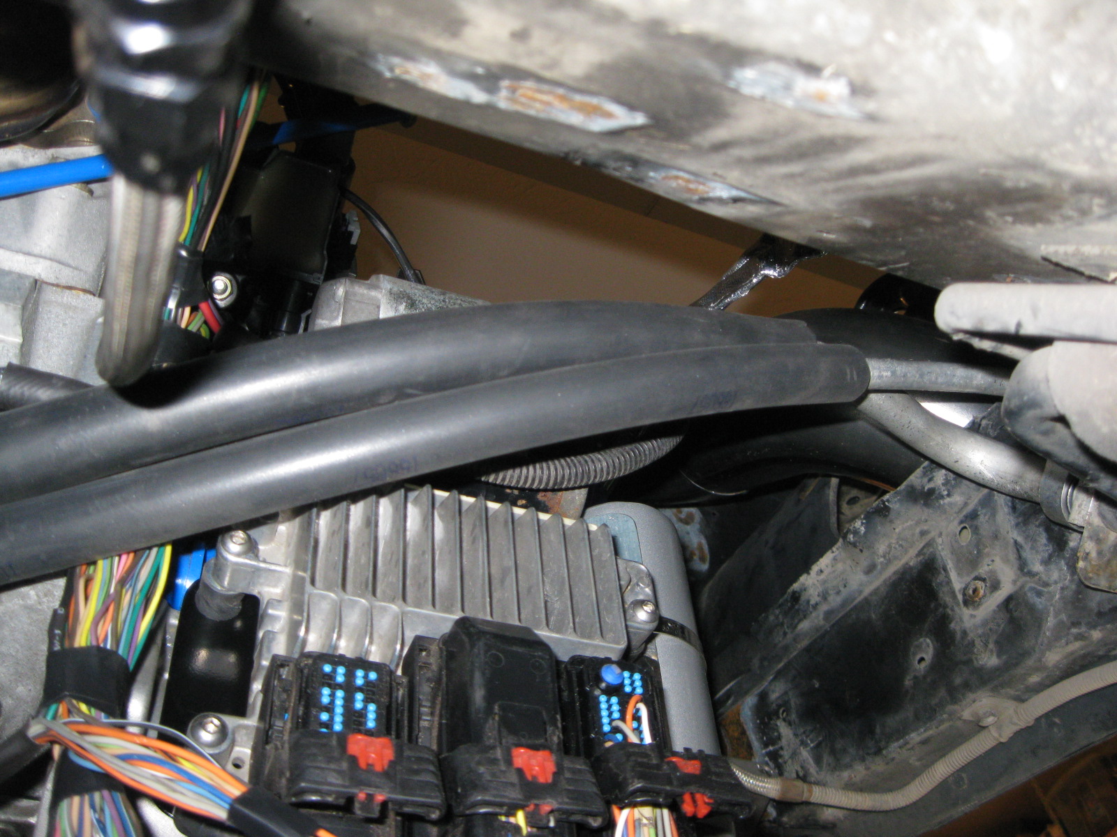
I made a new panel for the center console area and started to mount the components to it.
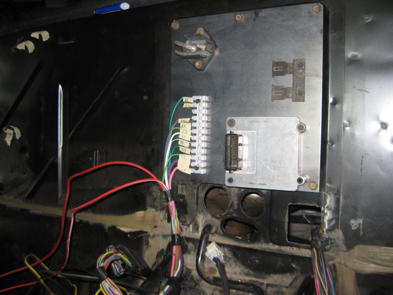
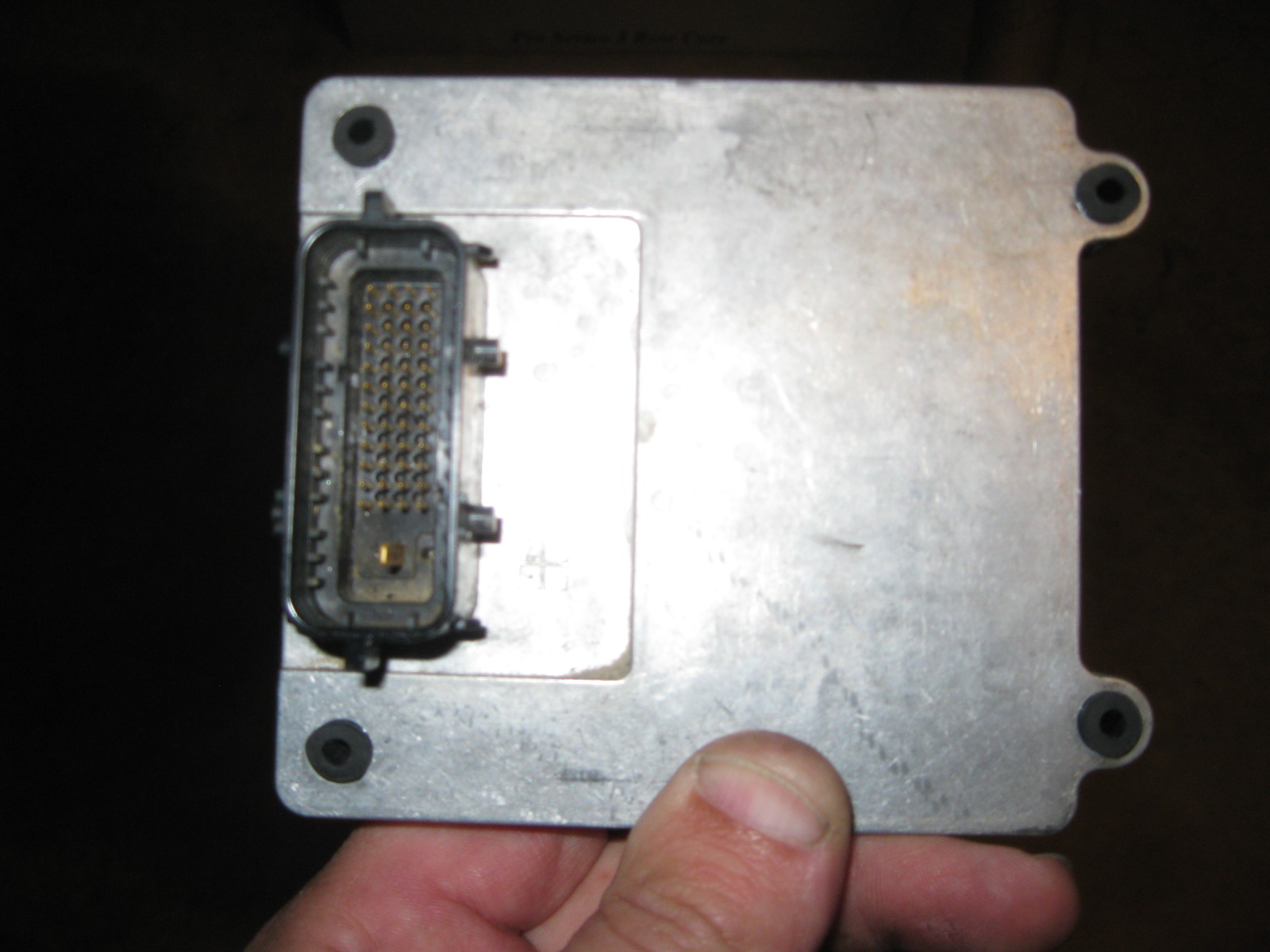
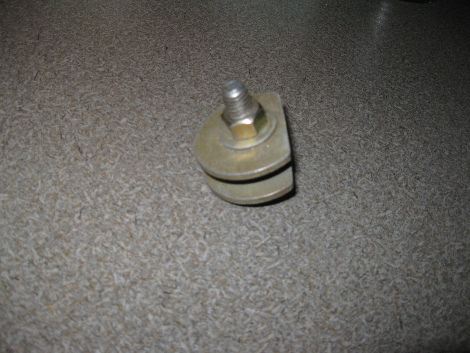
For mounting the TCM, I forced some vacuum lines through the mounting holes and cut them off with about 1/8" sticking through both sides. Then I could use typical fiero interior screws to bolt it down and keep it isolated. As I tightened the screw, the vacuum line mushroomed out some.
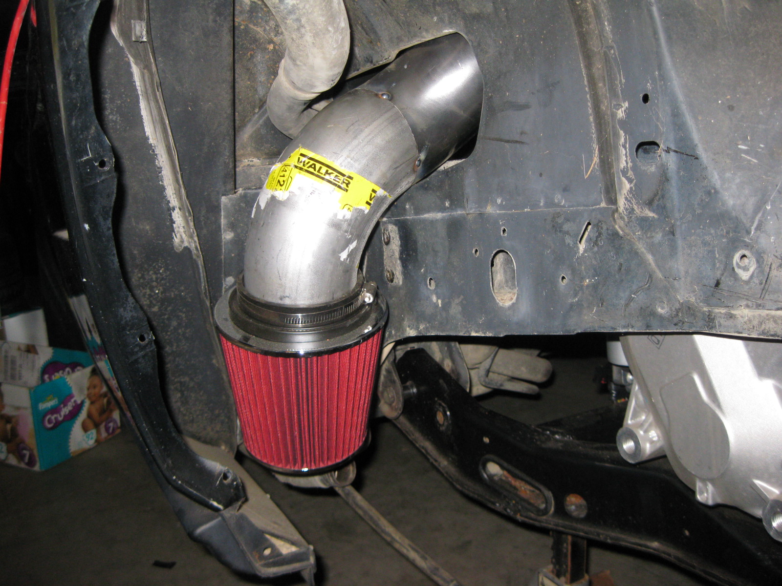
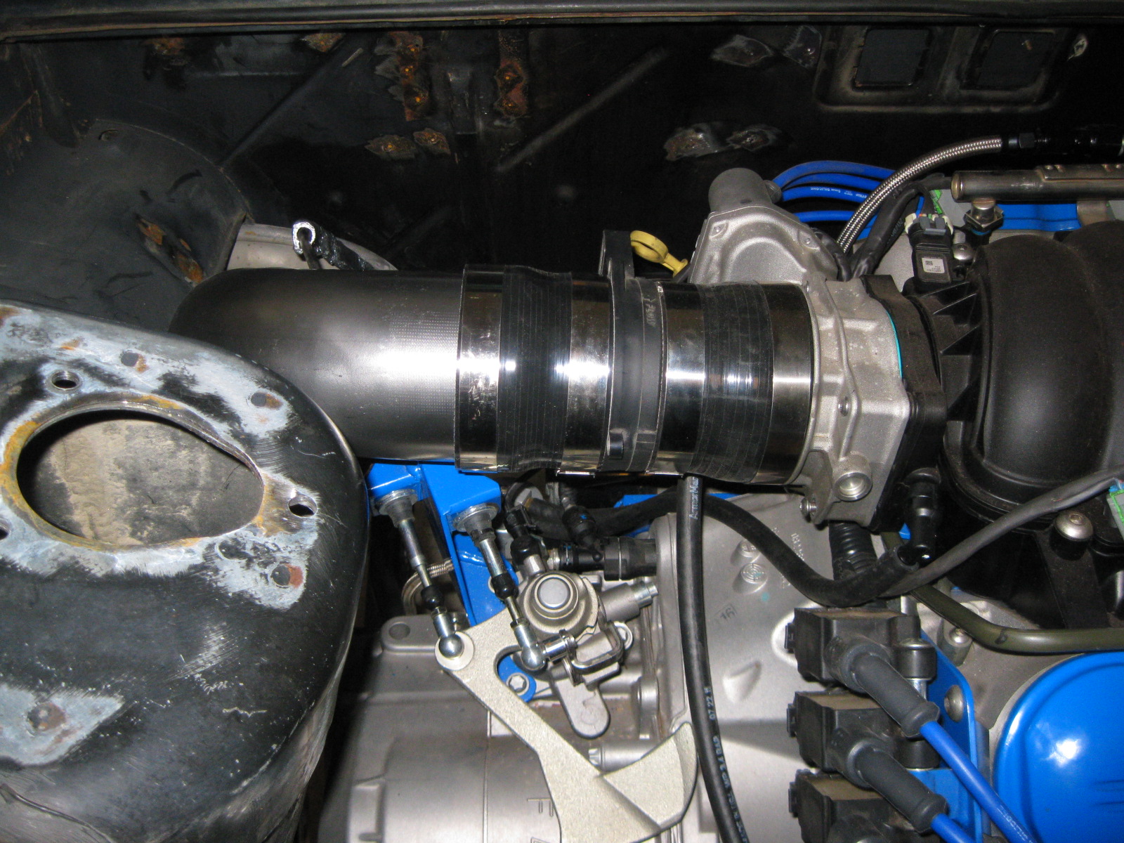
The other silicone reducer came in today... looks much better than the electrical tape I have been using to hold it still. Once the swap is running and tuned, I will probably switch to the card style MAF and extend the tube. That will streamline the inlet tract and allow the MAF to be hidden and one of the couplers to go away.
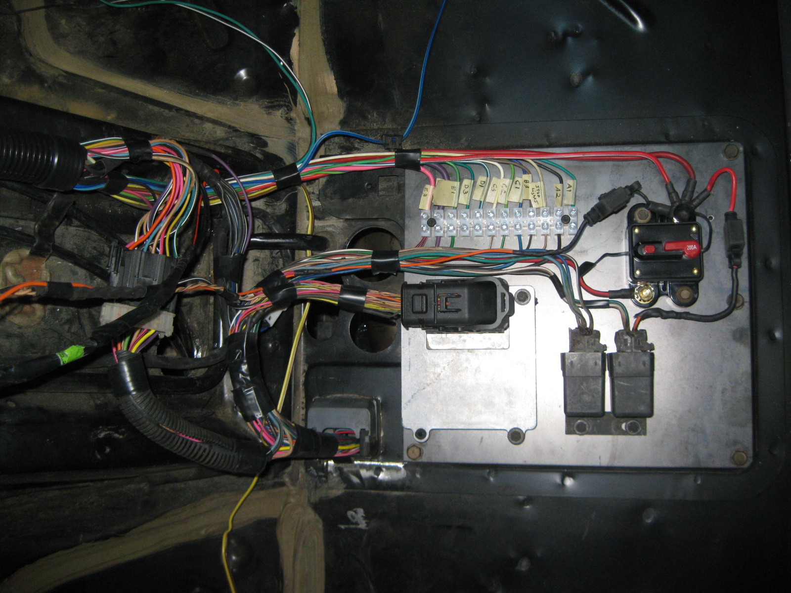
Finally finished with the inside wiring...
Ordered my Battery.
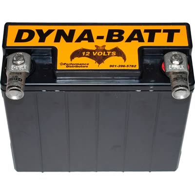
http://www.summitracing.com/parts/dui-5575a
Since this is a non-aero notchie, I can't mount the battery under the headlight like I usually do. This swap also has me more weight conscious than normal and looking for ways to save weight vs. my old SBC/Getrag swap. So both of these items will have me experimenting with a Dyna-Batt battery. The battery has a 7 x 3 x 6.5 foot print and weights only 13.5 lbs... a 20 lb savings from a stock Fiero battery and its small size should allow it to be mounted between the spare tire tub and the radiator and not in the spare tire tub at all. This would provide access for jump starting and require just 4 mounting holes (after I fab up a bracket to hold it).
Battery relocation cables are on order.
The A/C line ferrules arrived today so I put the A/C hose together. I did have to enlarge the offset hole in the ferrules to slide them over the factory ridges, but that wasn't much work for the die grinder.
On Thursday I will run to Napa over lunch and have then crimp the ferrules for me.
For mounting the TCM, I forced some vacuum lines through the mounting holes and cut them off with about 1/8" sticking through both sides. Then I could use typical fiero interior screws to bolt it down and keep it isolated. As I tightened the screw, the vacuum line mushroomed out some.
The other silicone reducer came in today... looks much better than the electrical tape I have been using to hold it still. Once the swap is running and tuned, I will probably switch to the card style MAF and extend the tube. That will streamline the inlet tract and allow the MAF to be hidden and one of the couplers to go away.
Finally finished with the inside wiring...
Ordered my Battery.
http://www.summitracing.com/parts/dui-5575a
Since this is a non-aero notchie, I can't mount the battery under the headlight like I usually do. This swap also has me more weight conscious than normal and looking for ways to save weight vs. my old SBC/Getrag swap. So both of these items will have me experimenting with a Dyna-Batt battery. The battery has a 7 x 3 x 6.5 foot print and weights only 13.5 lbs... a 20 lb savings from a stock Fiero battery and its small size should allow it to be mounted between the spare tire tub and the radiator and not in the spare tire tub at all. This would provide access for jump starting and require just 4 mounting holes (after I fab up a bracket to hold it).
Battery relocation cables are on order.
The A/C line ferrules arrived today so I put the A/C hose together. I did have to enlarge the offset hole in the ferrules to slide them over the factory ridges, but that wasn't much work for the die grinder.
On Thursday I will run to Napa over lunch and have then crimp the ferrules for me.
Last edited by fieroguru; 11-28-2012 at 05:13 PM.
 12-03-2012, 06:18 PM
#70
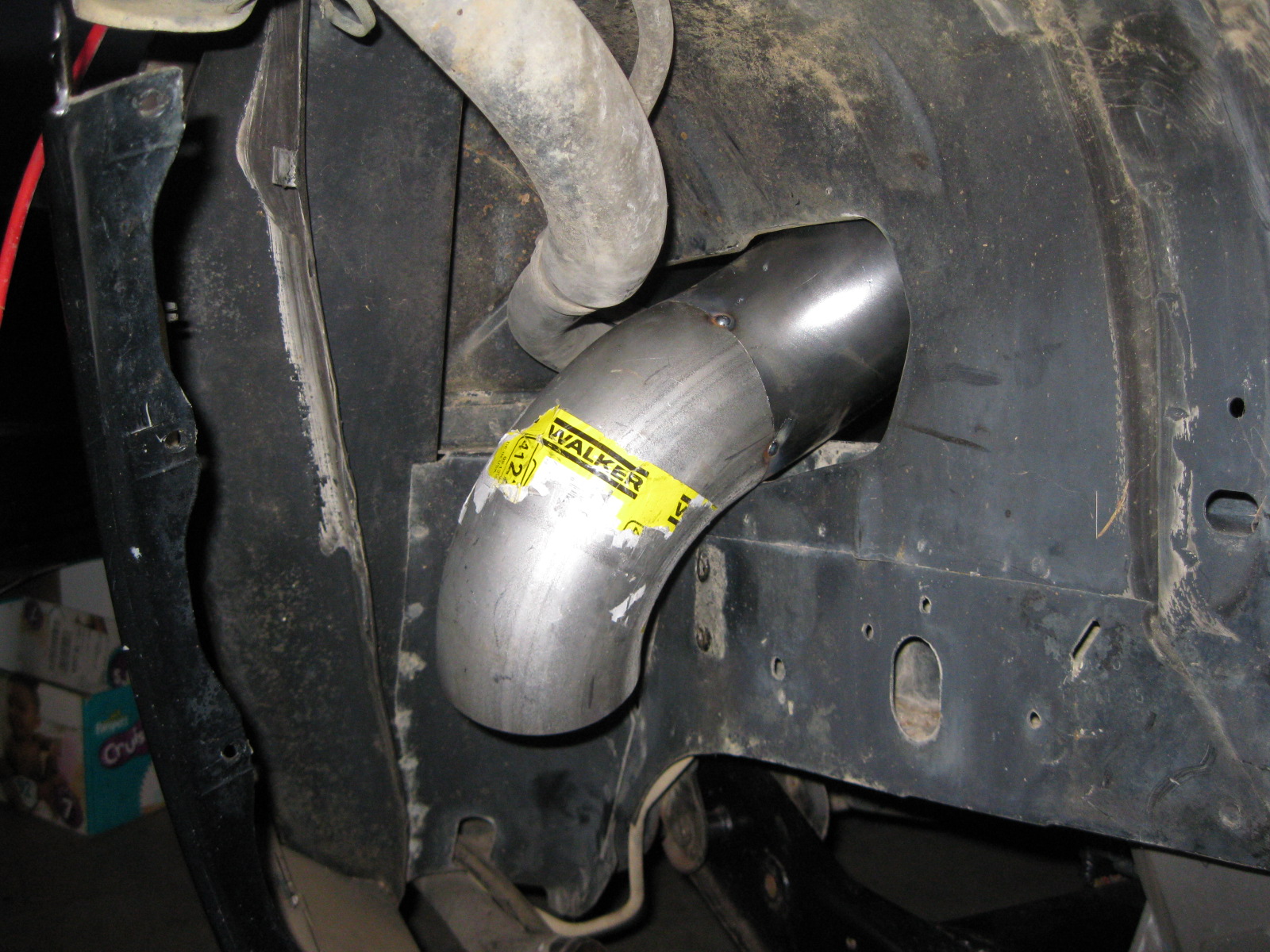
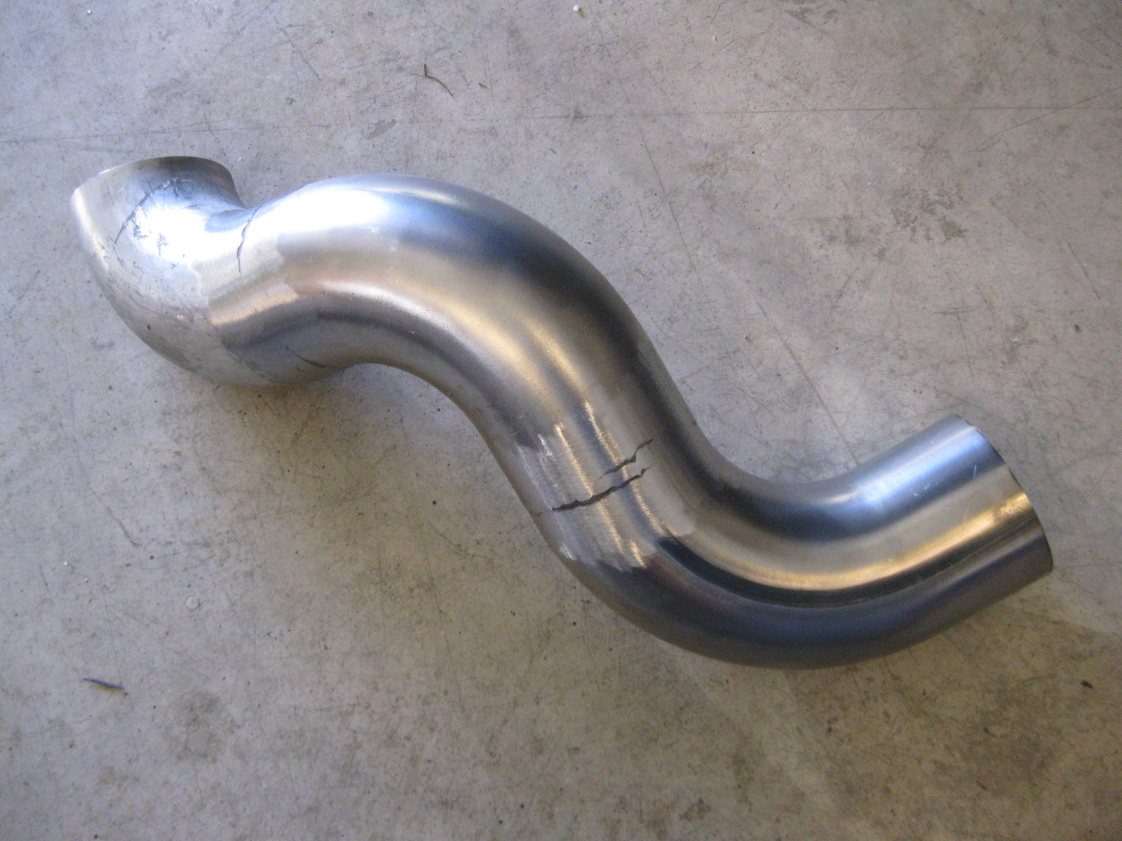
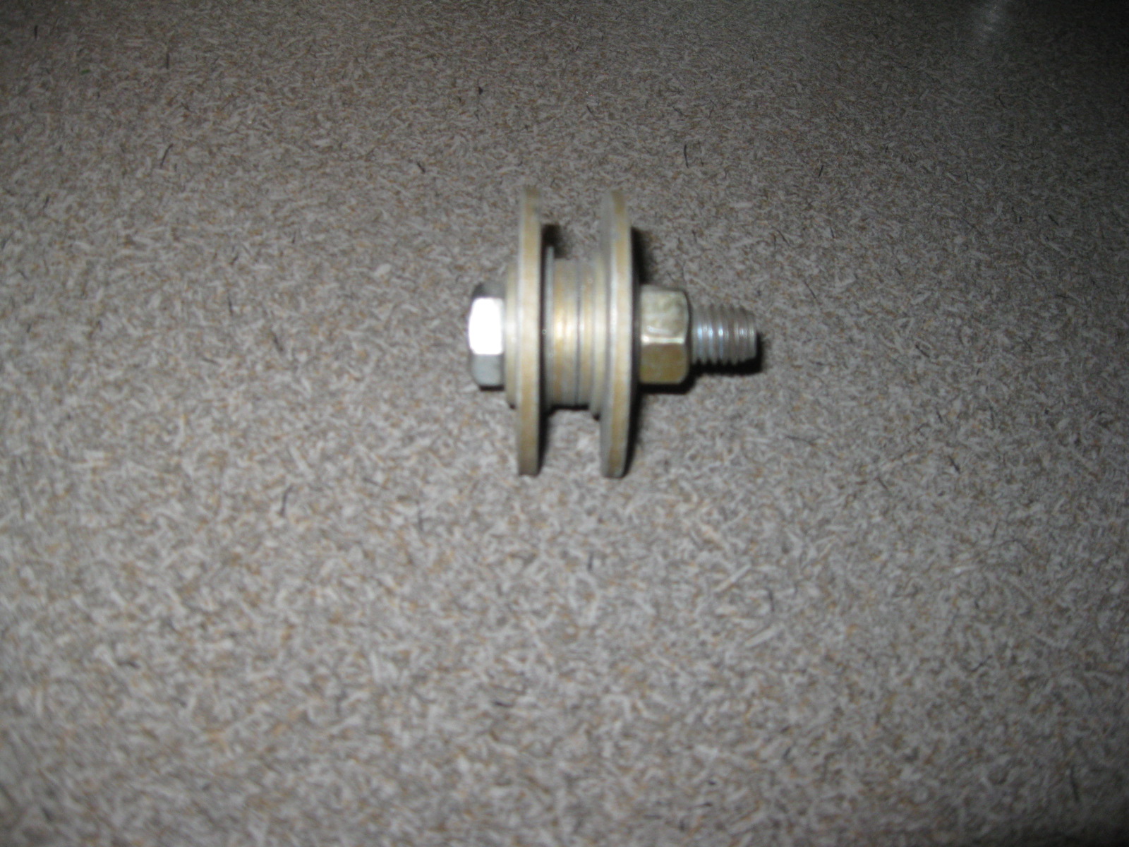
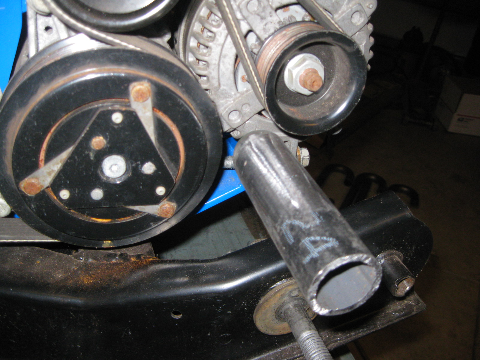
To make that bend, I made a small compact bender die from various sizes of washers. Clamped it to the tube to be bent, slid a screw driver into the tube and used the screw driver to bend the tube. Somewhat crude, but functional none the less.
 12-03-2012, 06:28 PM
#71
A/C lines crimped:
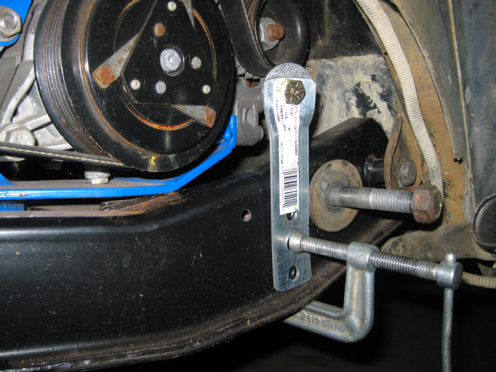
Before pulling the engine/tranny/cradle combo 1 last time (I hope), I made some guides for the approximate locations for the coolant hose connections:
Driver side:
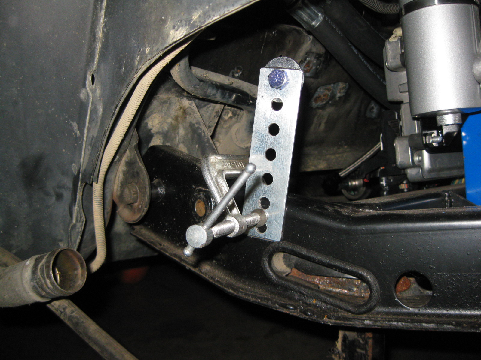
Passenger side:
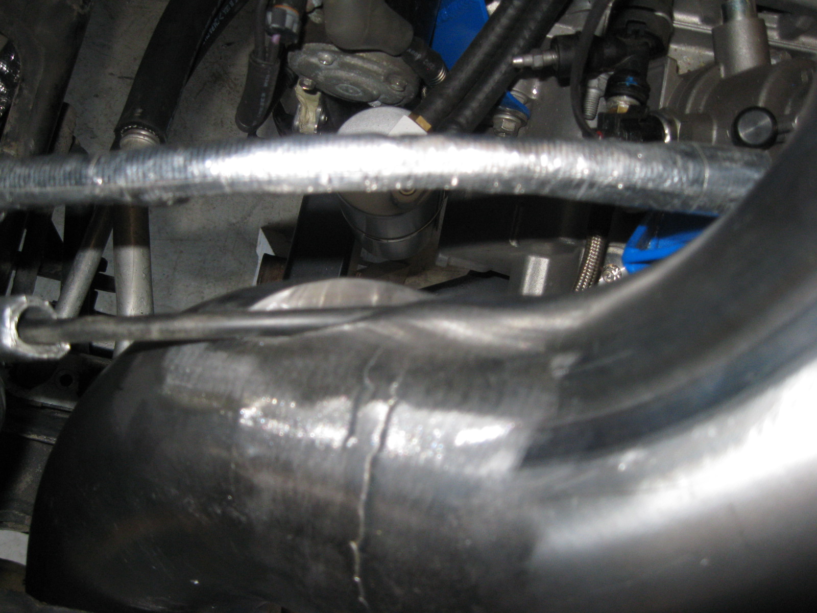
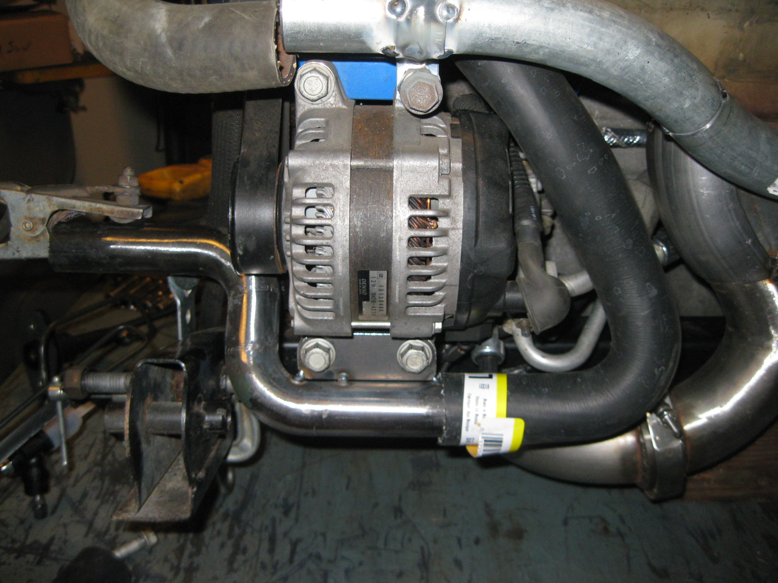
Everything is now back on the bench and the crossover coolant tube for the driver side is mocked up and tacked together:
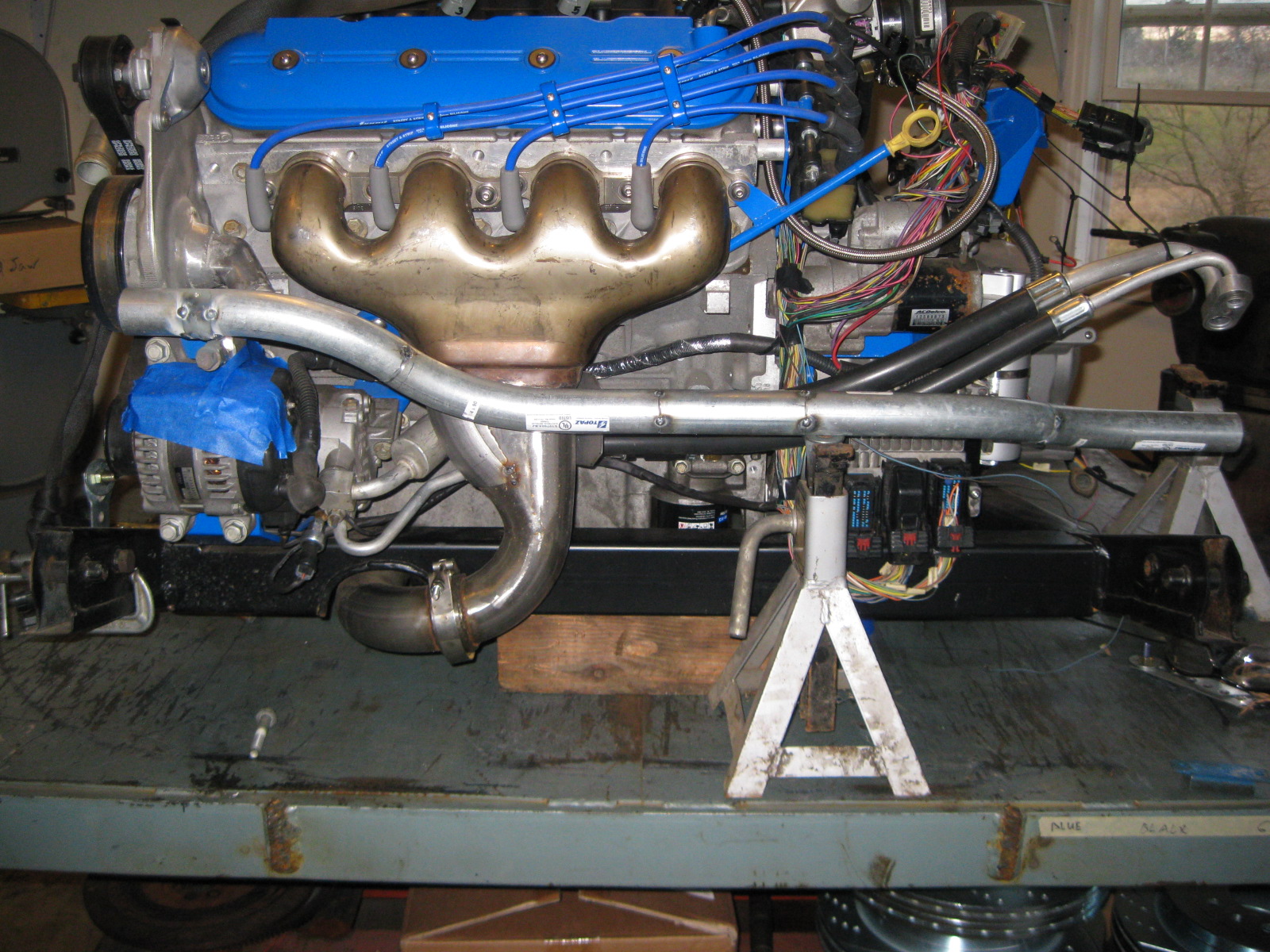
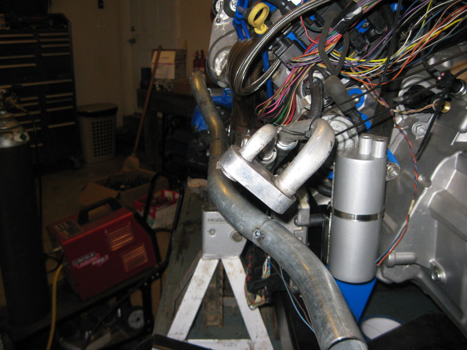
It is supported on the pulley side of the engine from a bracket off the alternator. I am fabbing up the bracket on the transmission side that will come off the catch can bracket.
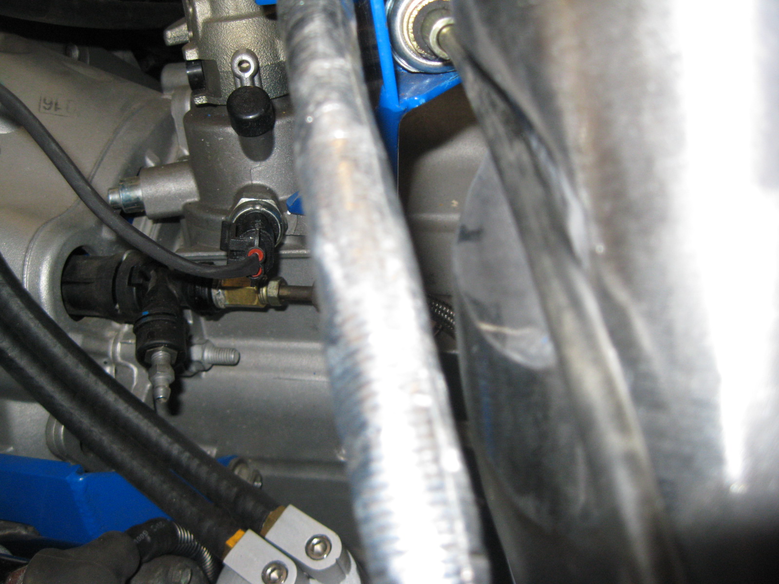
This was the easy side... the other one is very tight with little room...
Before pulling the engine/tranny/cradle combo 1 last time (I hope), I made some guides for the approximate locations for the coolant hose connections:
Driver side:
Passenger side:
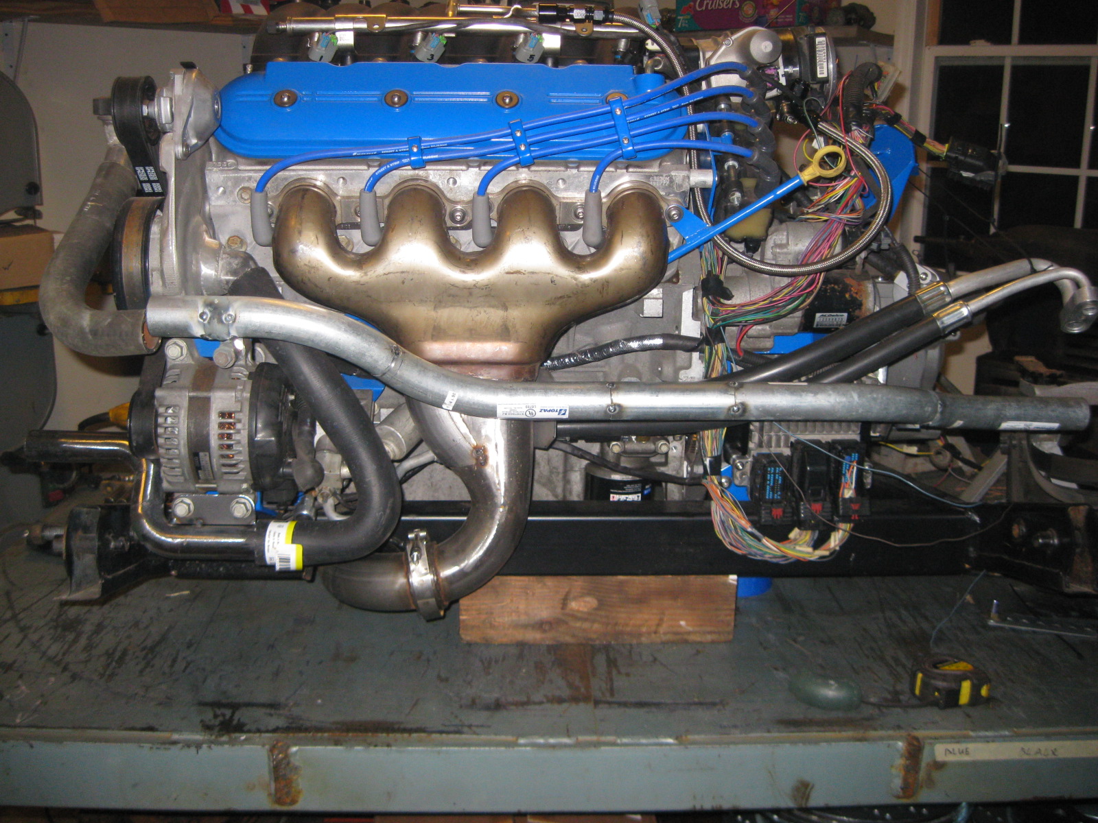
Everything is now back on the bench and the crossover coolant tube for the driver side is mocked up and tacked together:
It is supported on the pulley side of the engine from a bracket off the alternator. I am fabbing up the bracket on the transmission side that will come off the catch can bracket.
This was the easy side... the other one is very tight with little room...
12-04-2012, 06:55 AM
#73
The coil bossed were milled down, the small holes that remained were welded shut then I used a 4 1/2" flapper disk to smooth out the welds. I applied a thin coat of filler to level the modified areas. The main body of the valve covers were pretty smooth so a little scuffing was all I did for them.
If I had to do it again, I would have removed the internal baffle plates first, welded up the dimples under the bosses, then remove the bosses vs. removing the bosses first and then filling the holes from the dimples.
If I had to do it again, I would have removed the internal baffle plates first, welded up the dimples under the bosses, then remove the bosses vs. removing the bosses first and then filling the holes from the dimples.
12-04-2012, 01:59 PM
#74
Teching In
iTrader: (2)

Join Date: Aug 2012
Location: Chilliwack , Bc
Posts: 28
Likes: 0
Received 0 Likes
on
0 Posts
crazy dude....just crazy !!!!
looks great cant wait to see the finished project ....i used to be a fiero guy back in the day started with my first car 85 Gt 4spd ..
major props for the fabrication skills !!!!

looks great cant wait to see the finished project ....i used to be a fiero guy back in the day started with my first car 85 Gt 4spd ..
major props for the fabrication skills !!!!
12-05-2012, 05:40 PM
#75
Thanks ZeroC!
I think the passenger side coolant tube is figured out.
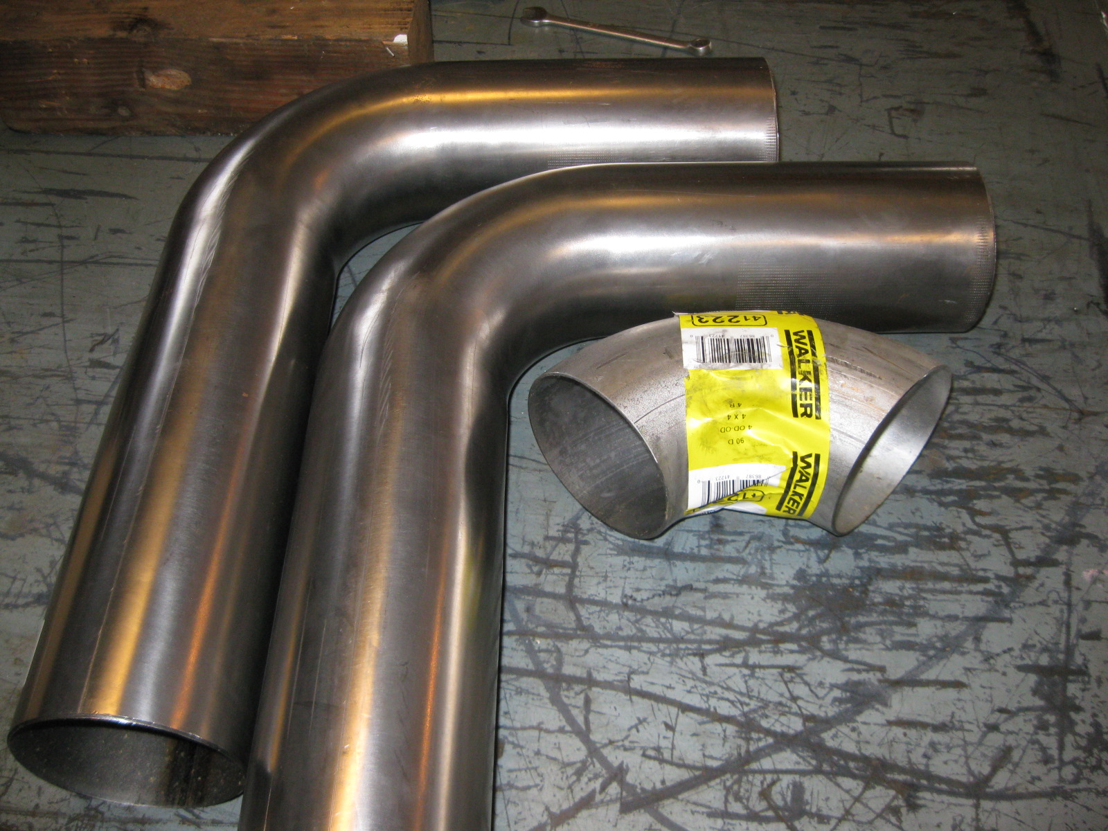
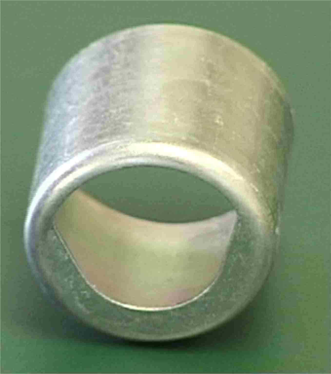
1" Schedule 40 black pipe is the perfect size for the fiero coolant hoses, so I ordered some butt-weld 90's to start with like this:
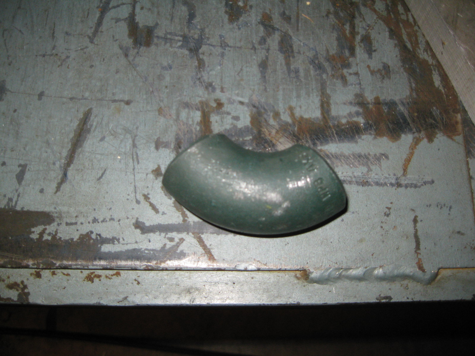
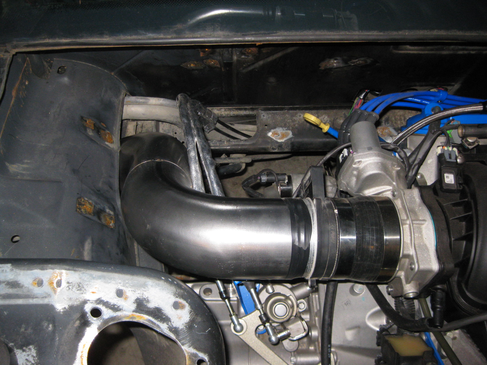
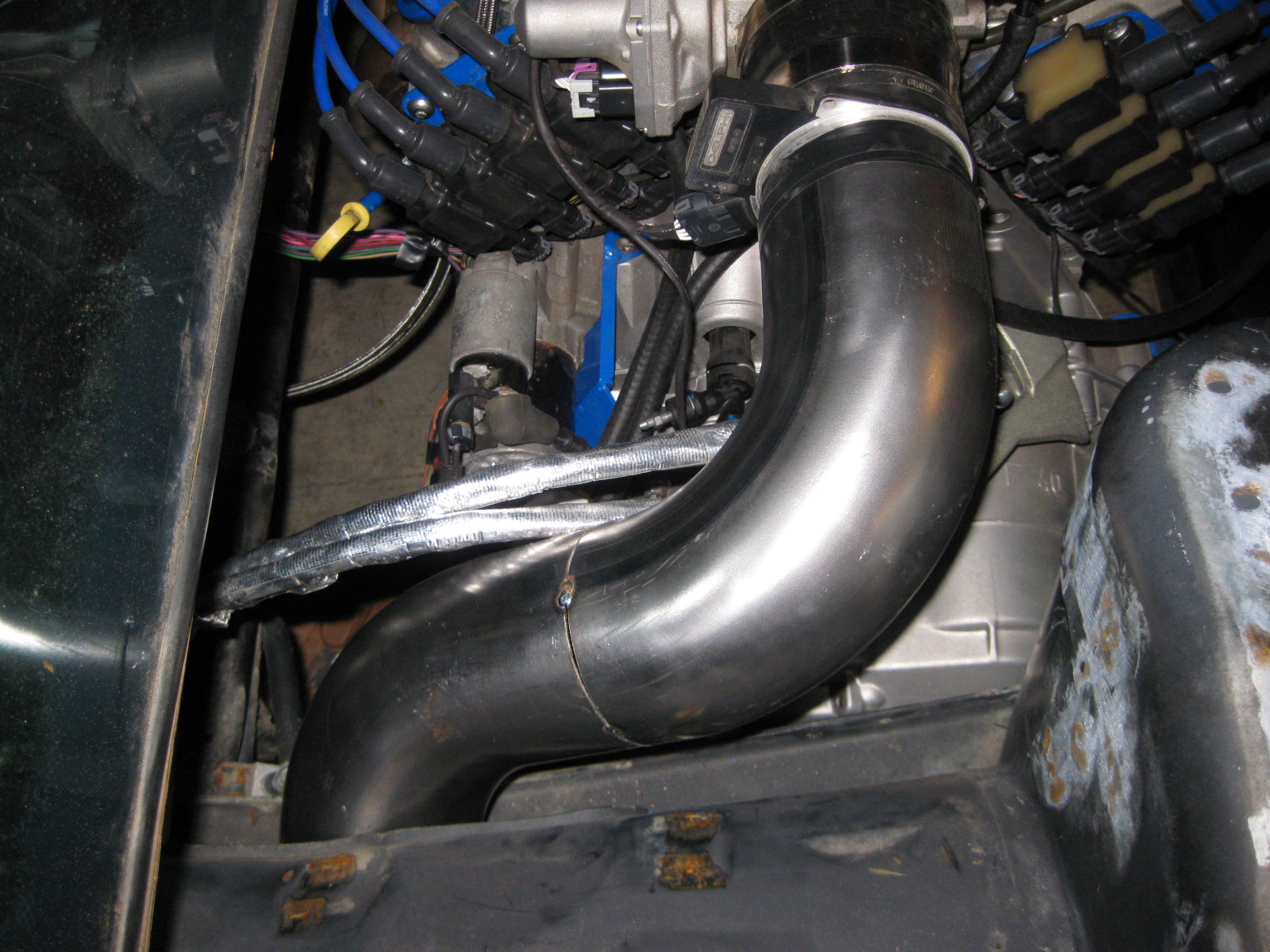
Then I just pieced them as well as some sections of pipe together and came up with this:
Just need to weld on the mounting tab (it is just tacked in place).
I think the passenger side coolant tube is figured out.
1" Schedule 40 black pipe is the perfect size for the fiero coolant hoses, so I ordered some butt-weld 90's to start with like this:
Then I just pieced them as well as some sections of pipe together and came up with this:
Just need to weld on the mounting tab (it is just tacked in place).
 12-06-2012, 05:22 AM
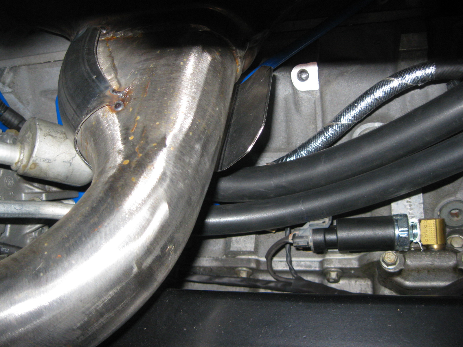
#78
For the long cross pipe, I used 16ga to keep the weight down, but you cant get as tight of bend radius with 16ga exhaust tubing and I needed something pretty tight to snake through the available space between the alternator and cradle.