88 Fiero Formula LS4/F40 6 speed swap
 01-14-2013, 06:32 PM
#101


Sure!
I broke my camera... it was on, lens extracted and took a tumble off the bench, jamming the lens/zoom mechanism and now it won't start. So I stole the wife's...
It took quite a bit longer to get the tops of the strut towers look good, but they are finally done!
Also reinstalled the decklid hinges (need the engine out to line up the bolt holes in the top plate):
Factory Hole:

Top plate being slid into place:
Hinge installed:
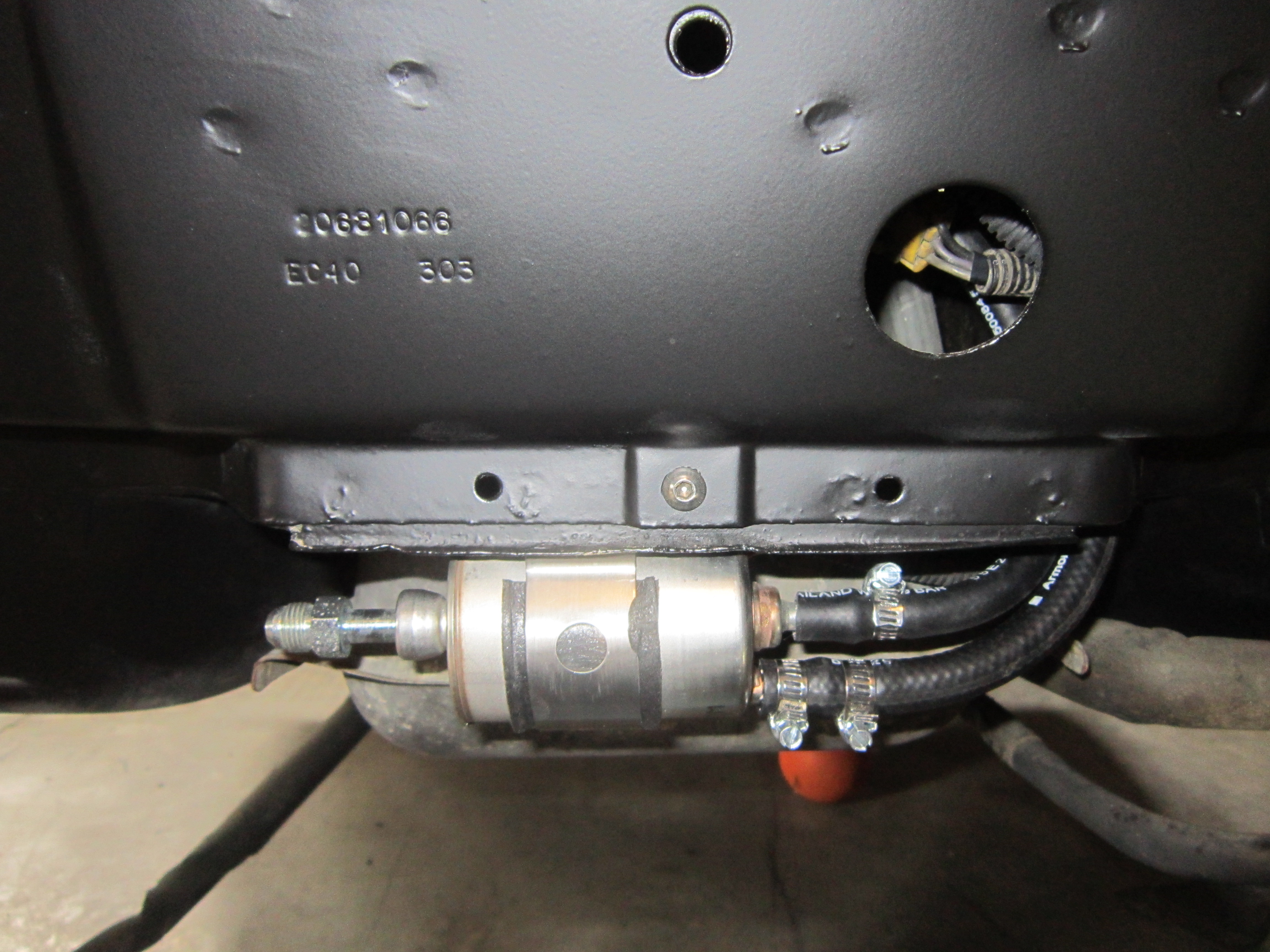
Then it was time to install the fuel tank and filter assy. Since I wasn't using the GM quick disconnects, I put a little bubble at the end to help ensure the hoses stay put:

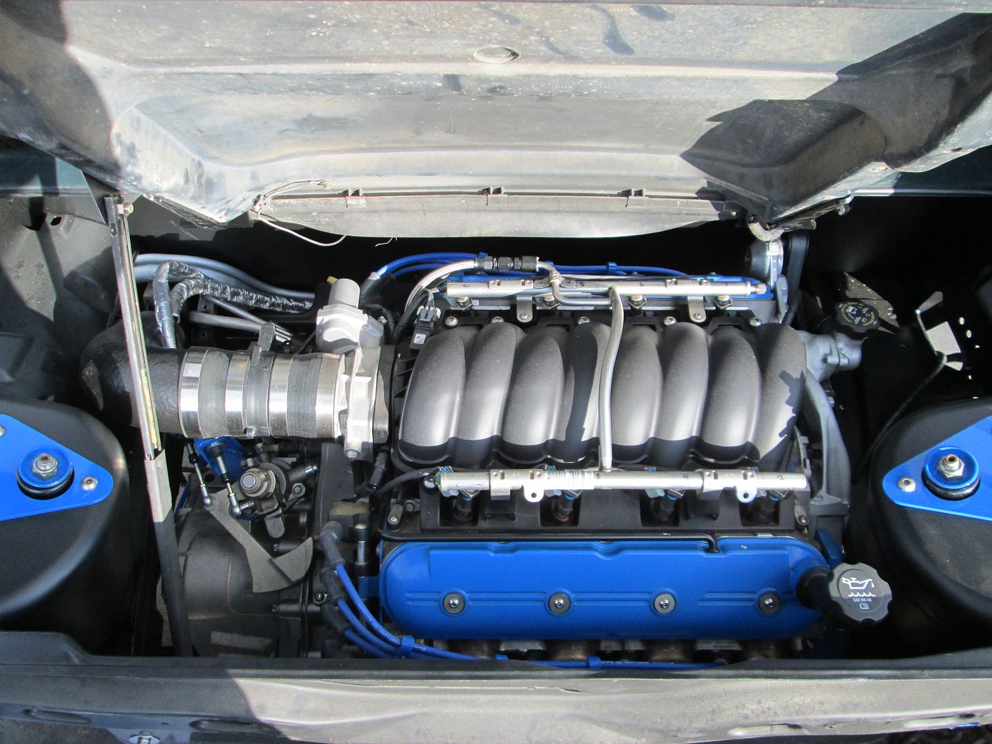
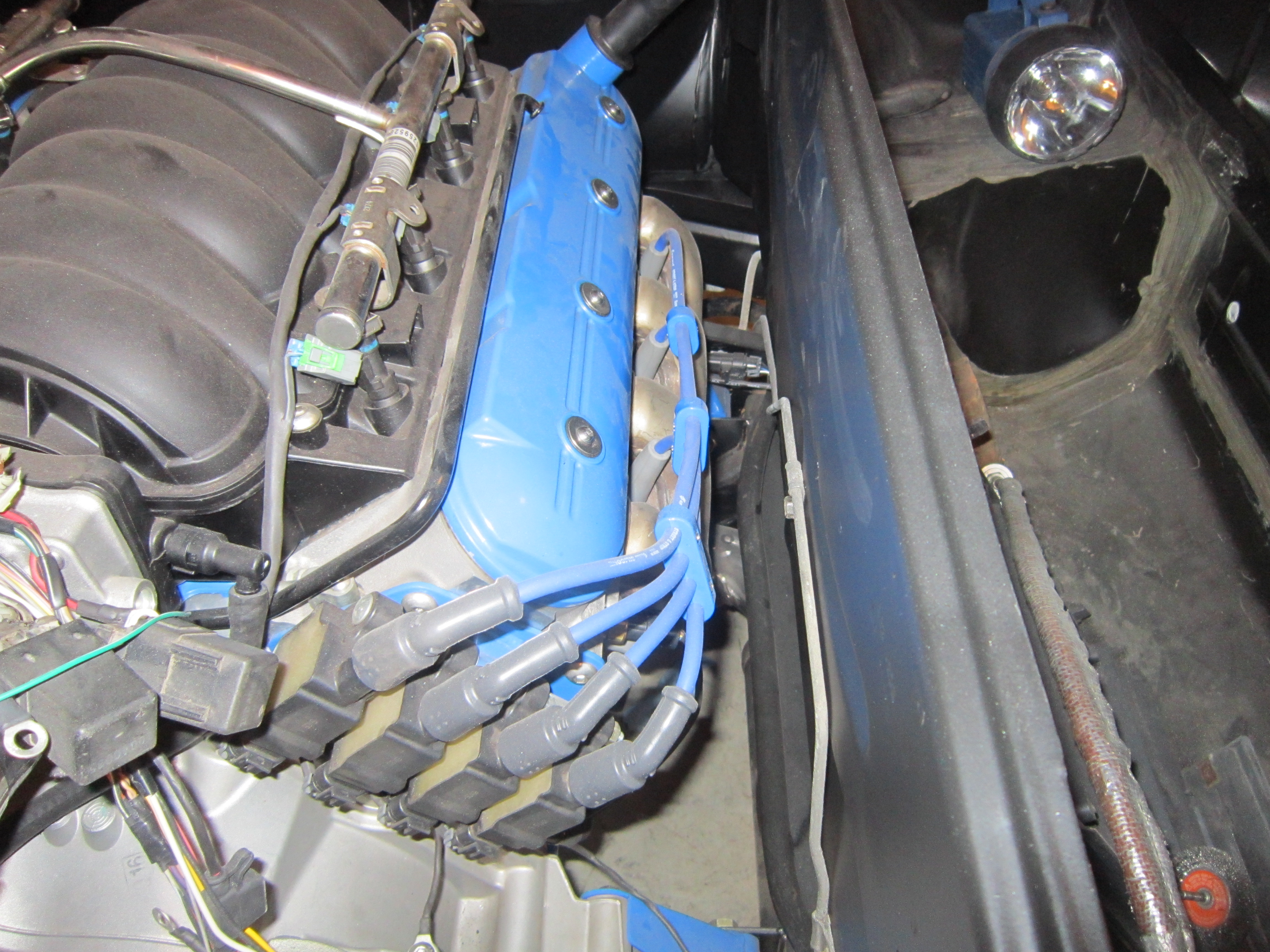
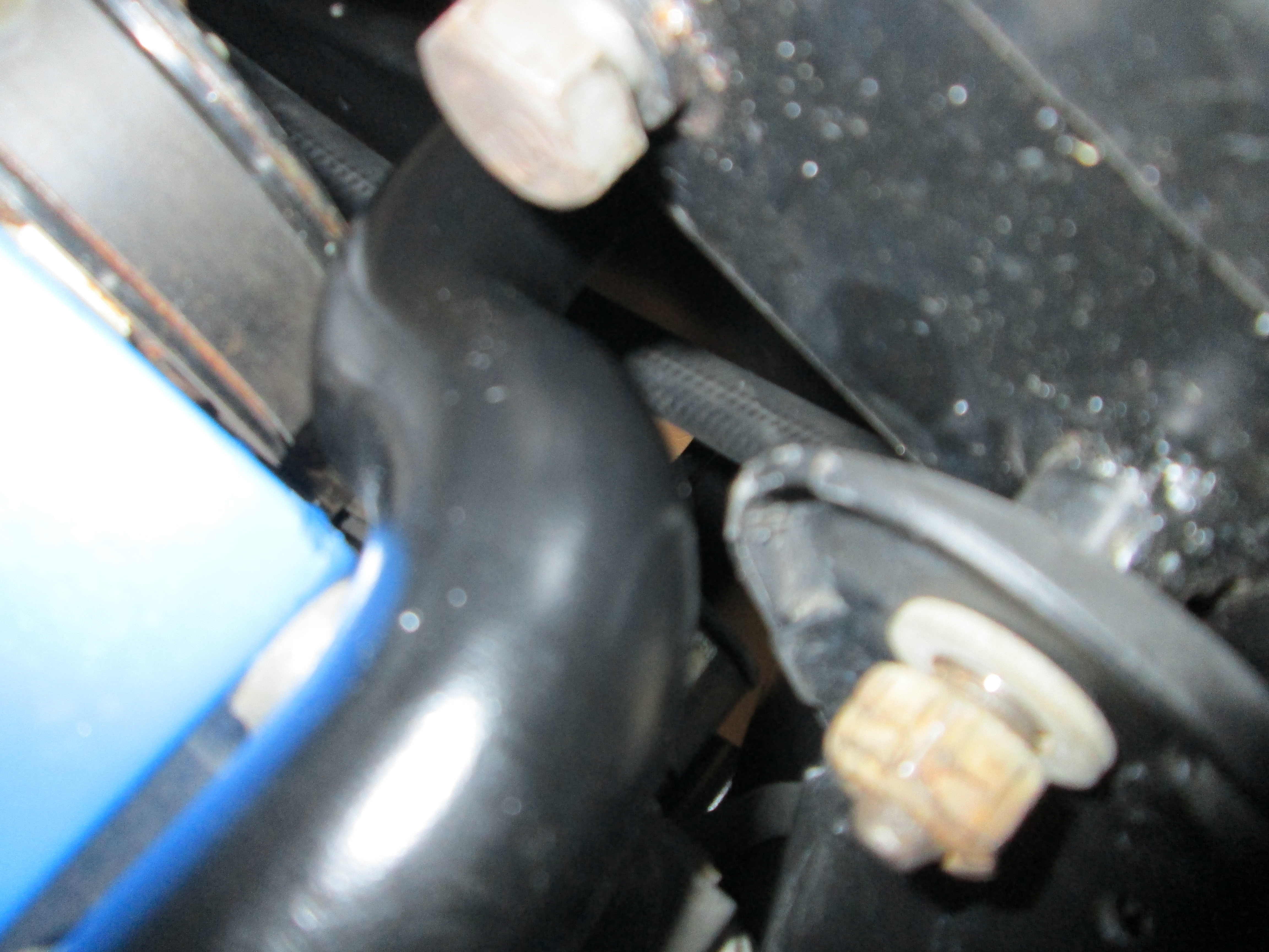
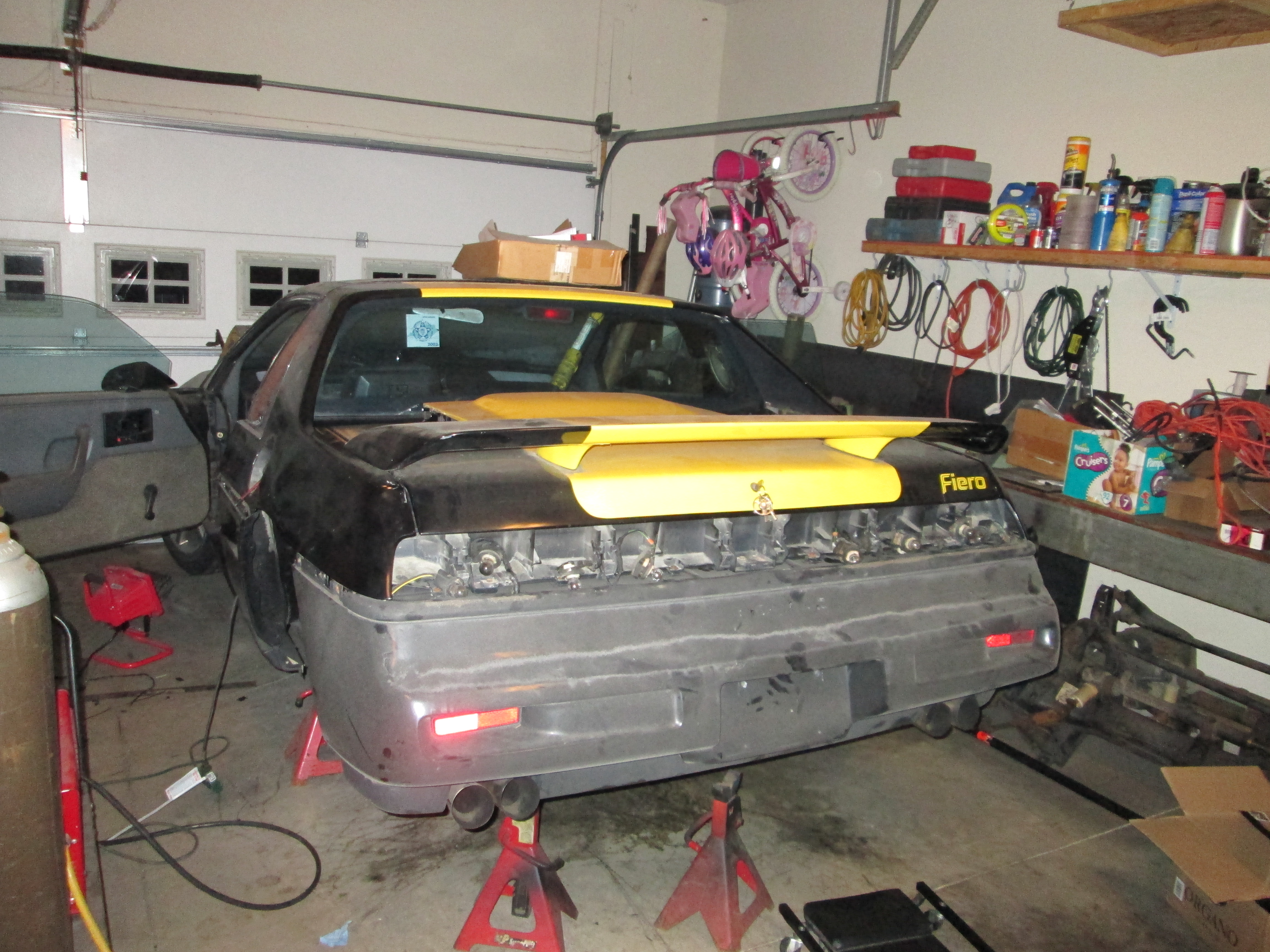
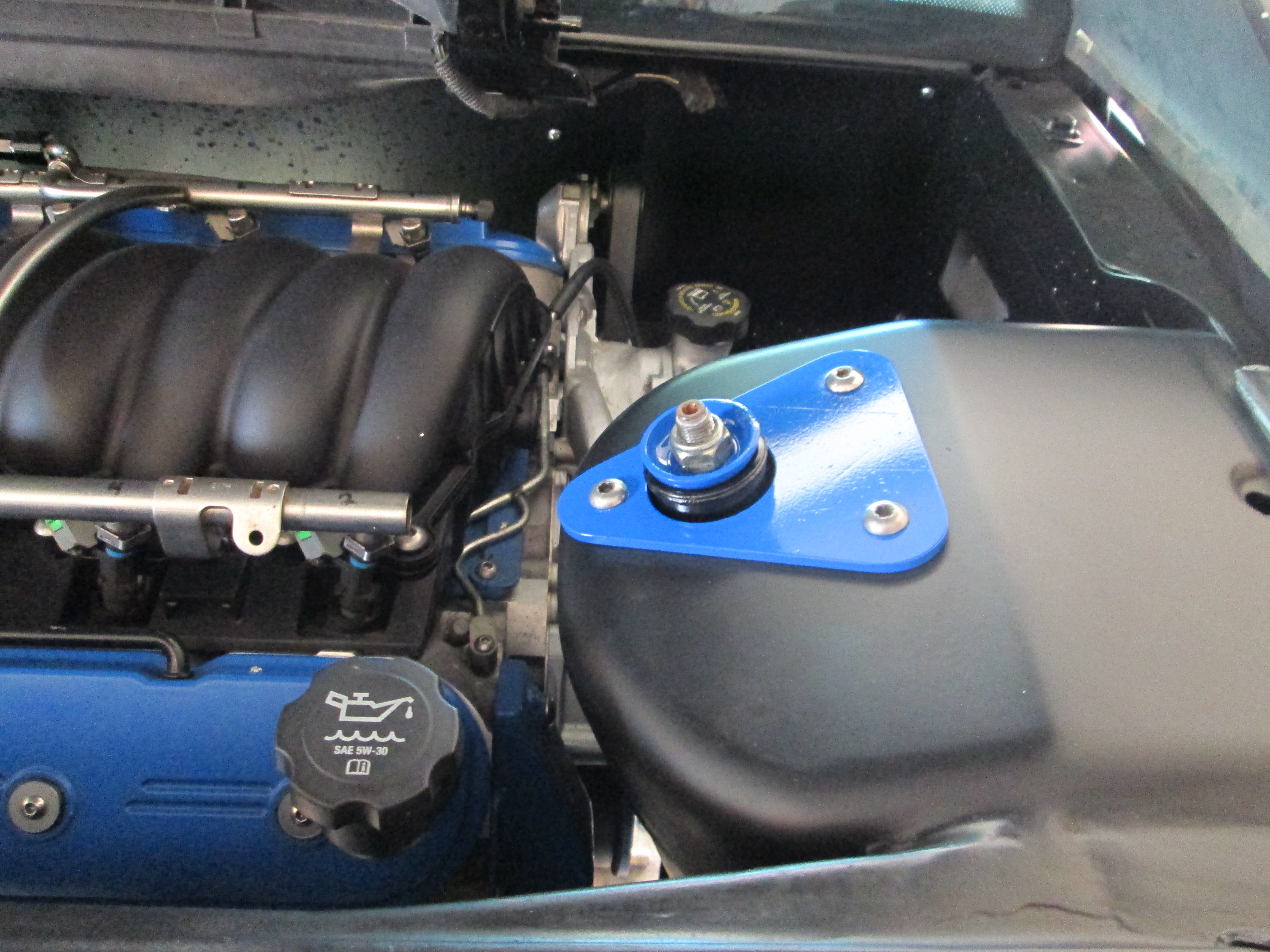
Then it was time to put the engine back in for what I thought was the final time... but alas the two coolant pipes didn't clear the chassis. The passenger side one is a simple fix (just need to remake the mounting tab to lower it and shift it about 1/2" to the DS (it hits the front cradle bolt bracket by about 1/4", and I am not cutting the bracket). The driver side one just needs a complete rework... I had it in and out about 5 times trimming it to fit, but now I think I will just make a new one. Besides the coolant tube issue, notice how much room there is between the firewall and the manifold (and it has a heat shield).
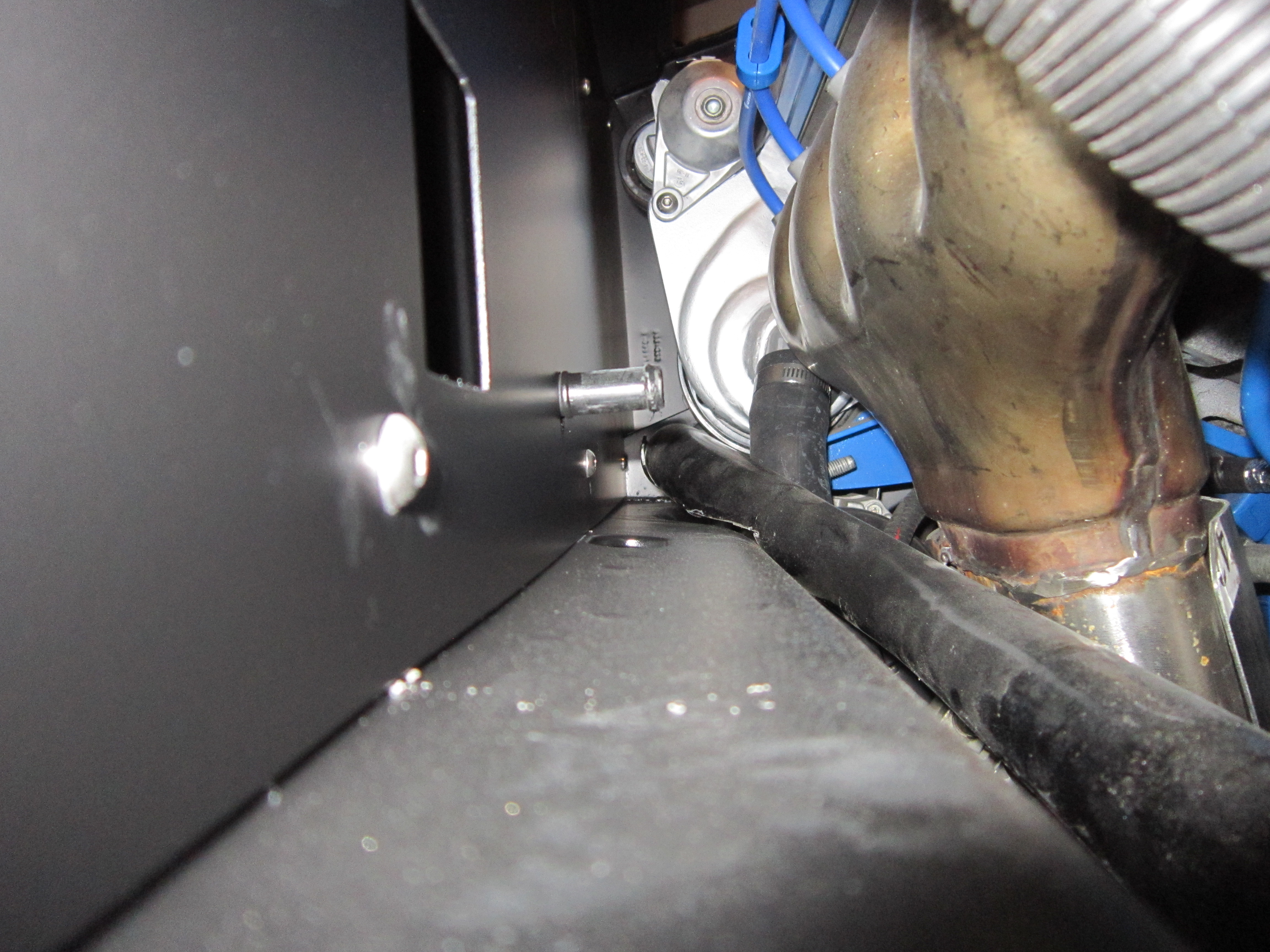
I will rework both coolant tubes with the cradle in the car so I will know the new ones will fit!
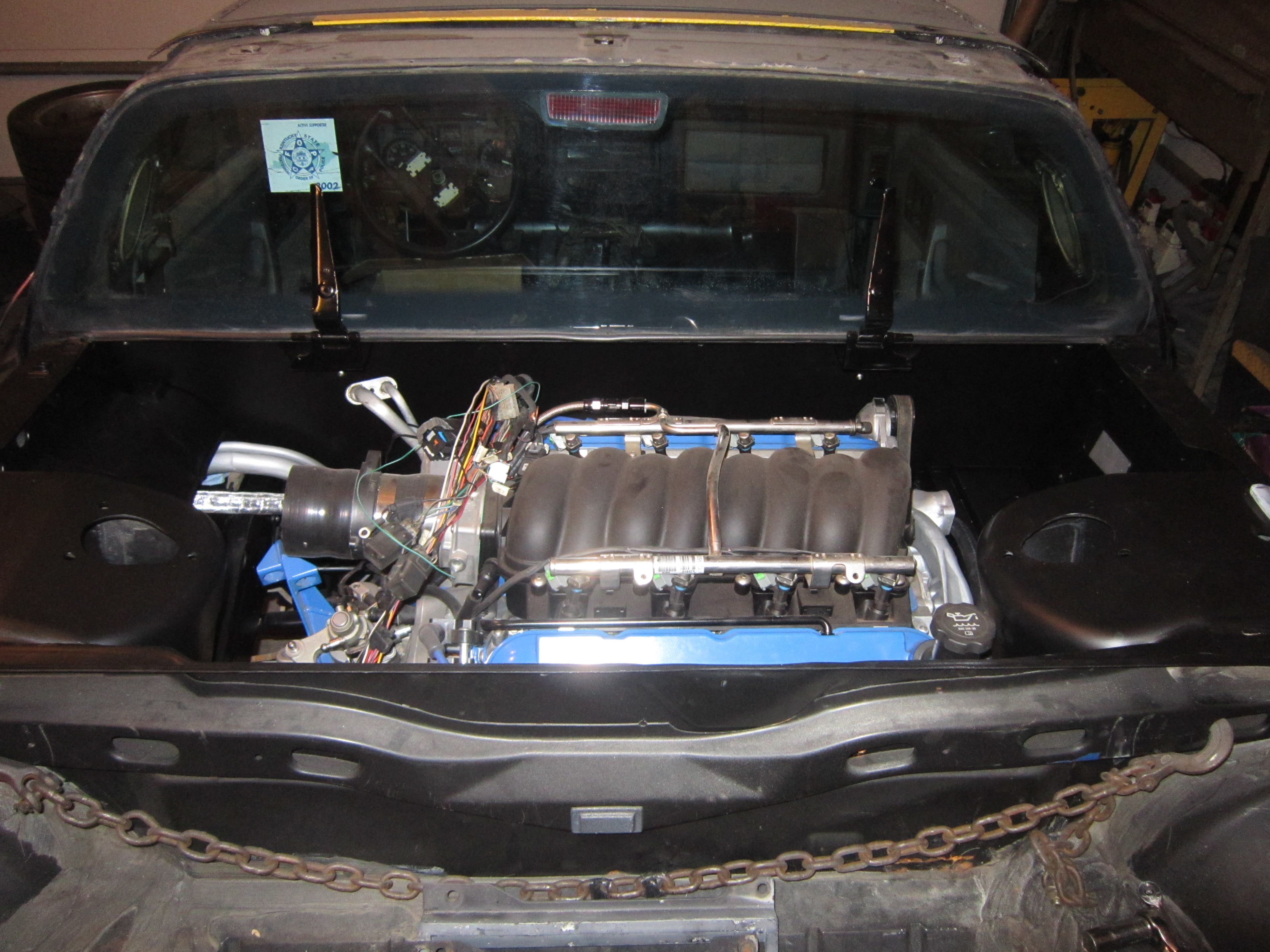
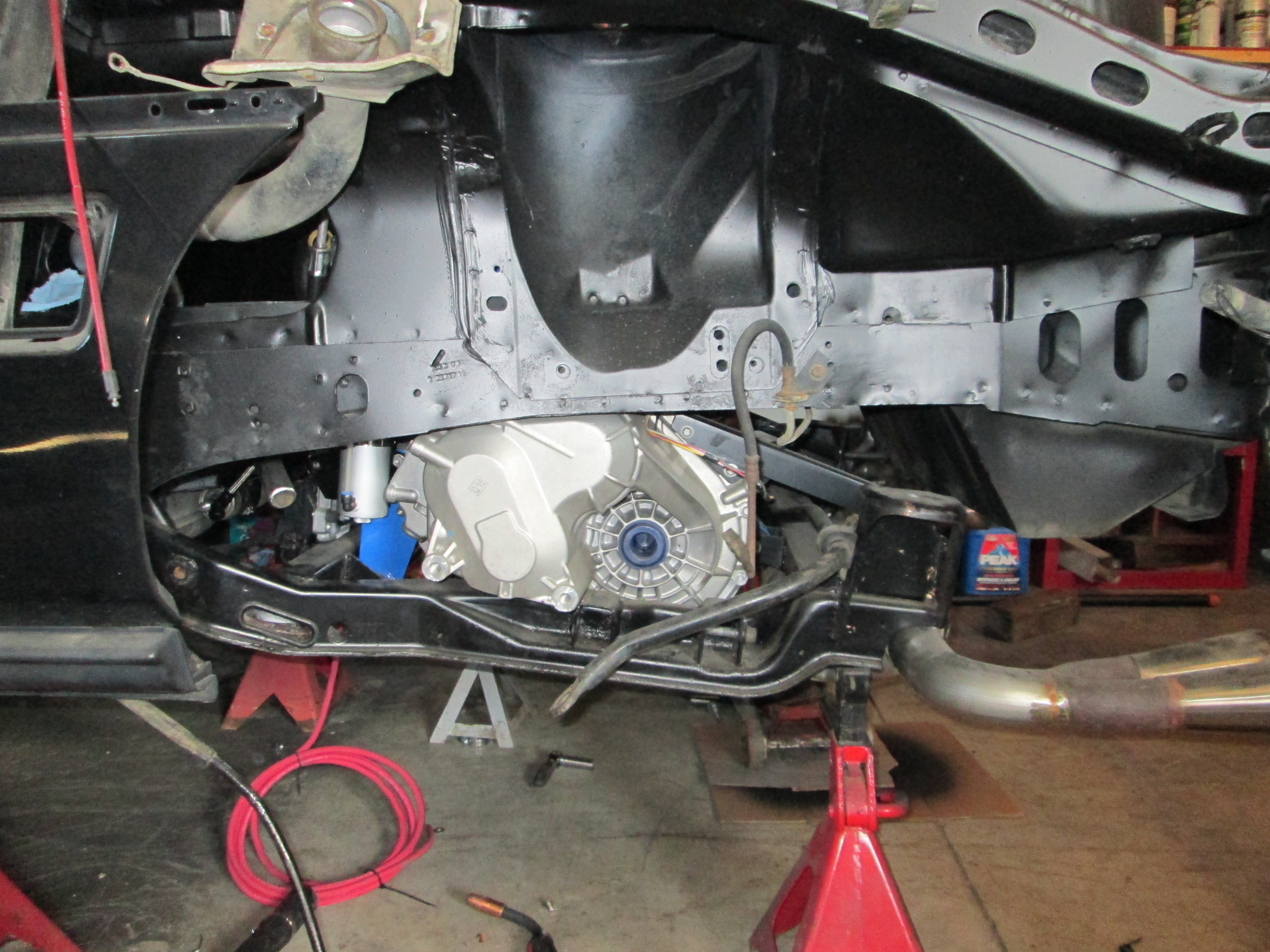
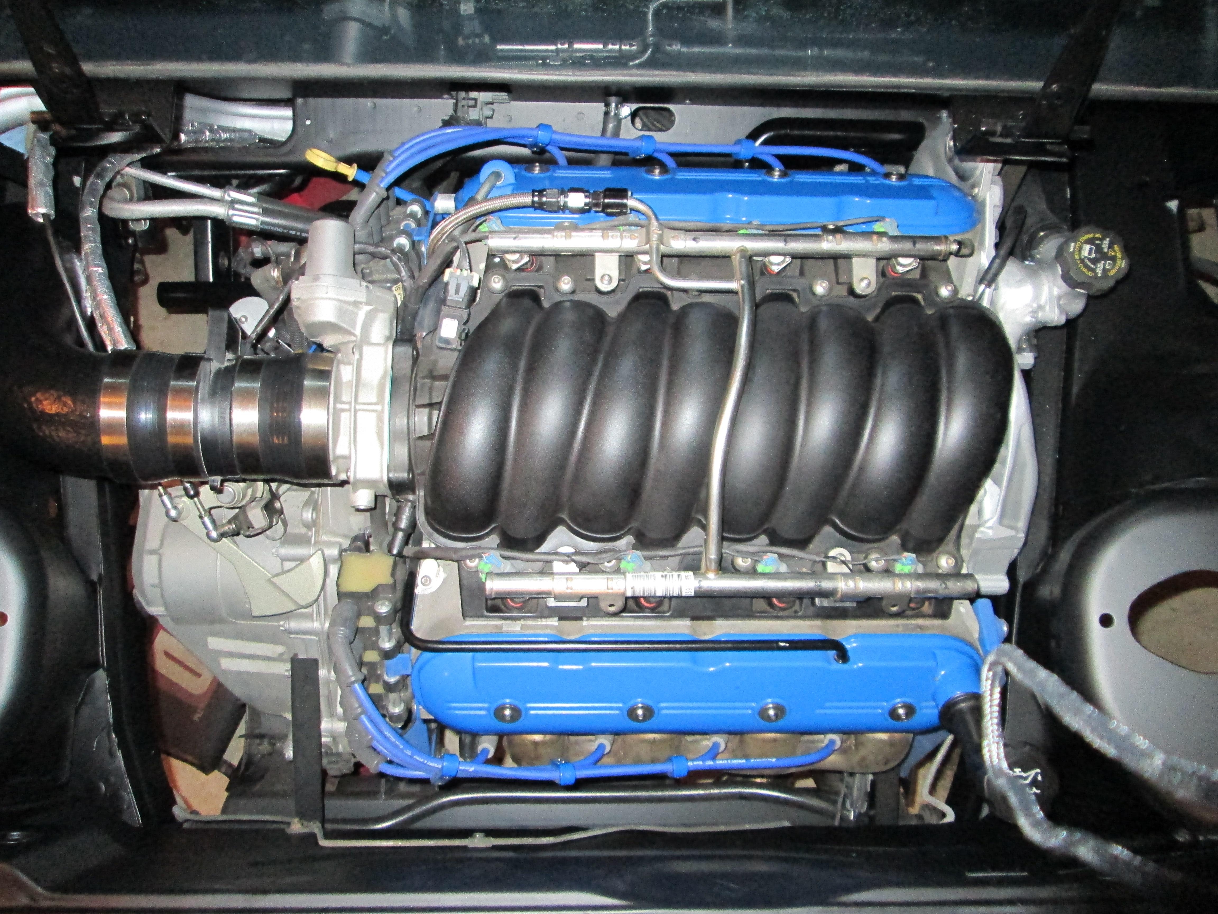
Here are some other general engine in bay pics (excuse the dust on the engine...):
I broke my camera... it was on, lens extracted and took a tumble off the bench, jamming the lens/zoom mechanism and now it won't start. So I stole the wife's...
It took quite a bit longer to get the tops of the strut towers look good, but they are finally done!
Also reinstalled the decklid hinges (need the engine out to line up the bolt holes in the top plate):
Factory Hole:
Top plate being slid into place:
Hinge installed:
Then it was time to install the fuel tank and filter assy. Since I wasn't using the GM quick disconnects, I put a little bubble at the end to help ensure the hoses stay put:
Then it was time to put the engine back in for what I thought was the final time... but alas the two coolant pipes didn't clear the chassis. The passenger side one is a simple fix (just need to remake the mounting tab to lower it and shift it about 1/2" to the DS (it hits the front cradle bolt bracket by about 1/4", and I am not cutting the bracket). The driver side one just needs a complete rework... I had it in and out about 5 times trimming it to fit, but now I think I will just make a new one. Besides the coolant tube issue, notice how much room there is between the firewall and the manifold (and it has a heat shield).
I will rework both coolant tubes with the cradle in the car so I will know the new ones will fit!
Here are some other general engine in bay pics (excuse the dust on the engine...):
 01-20-2013, 12:47 PM
#102
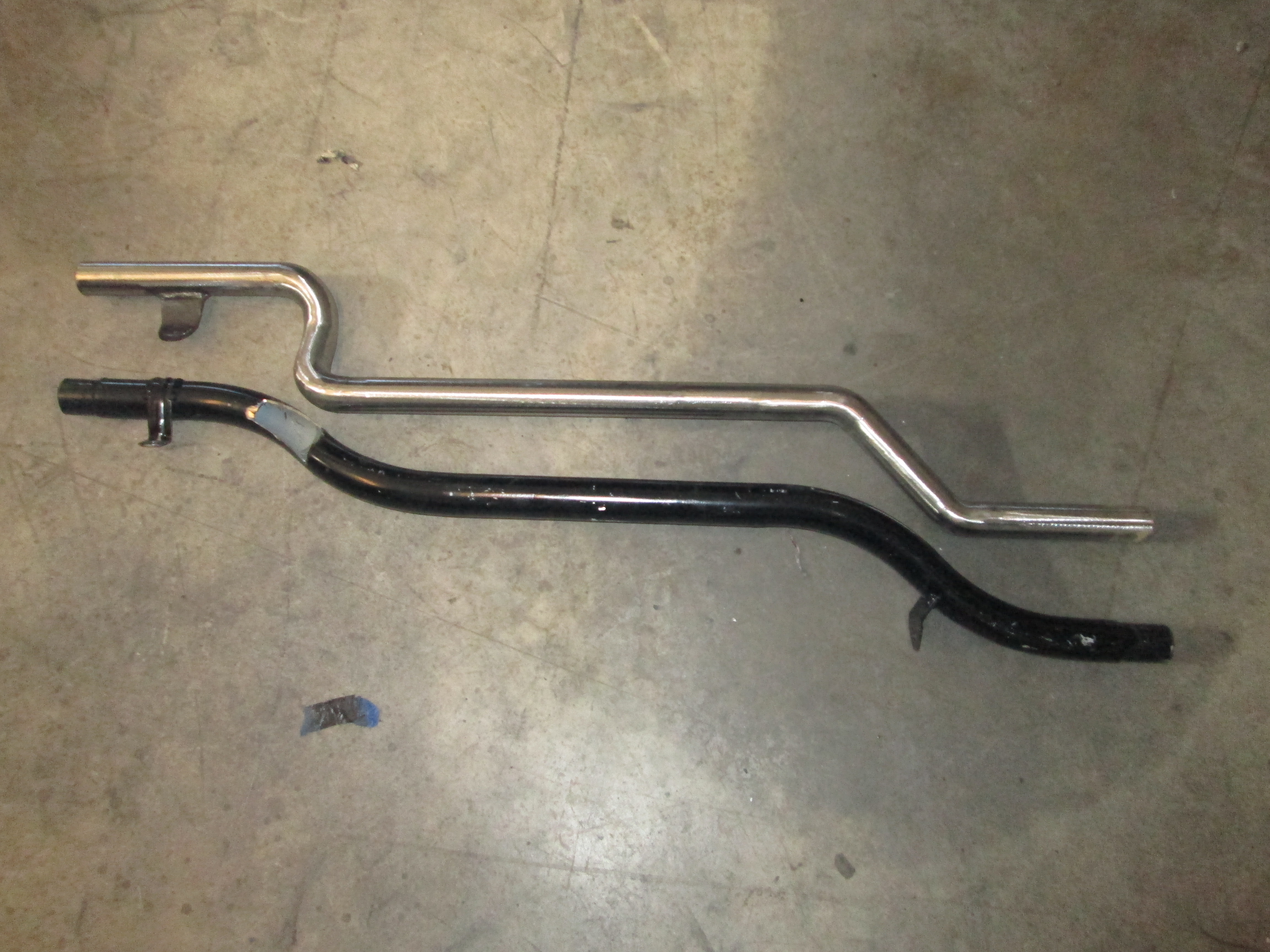
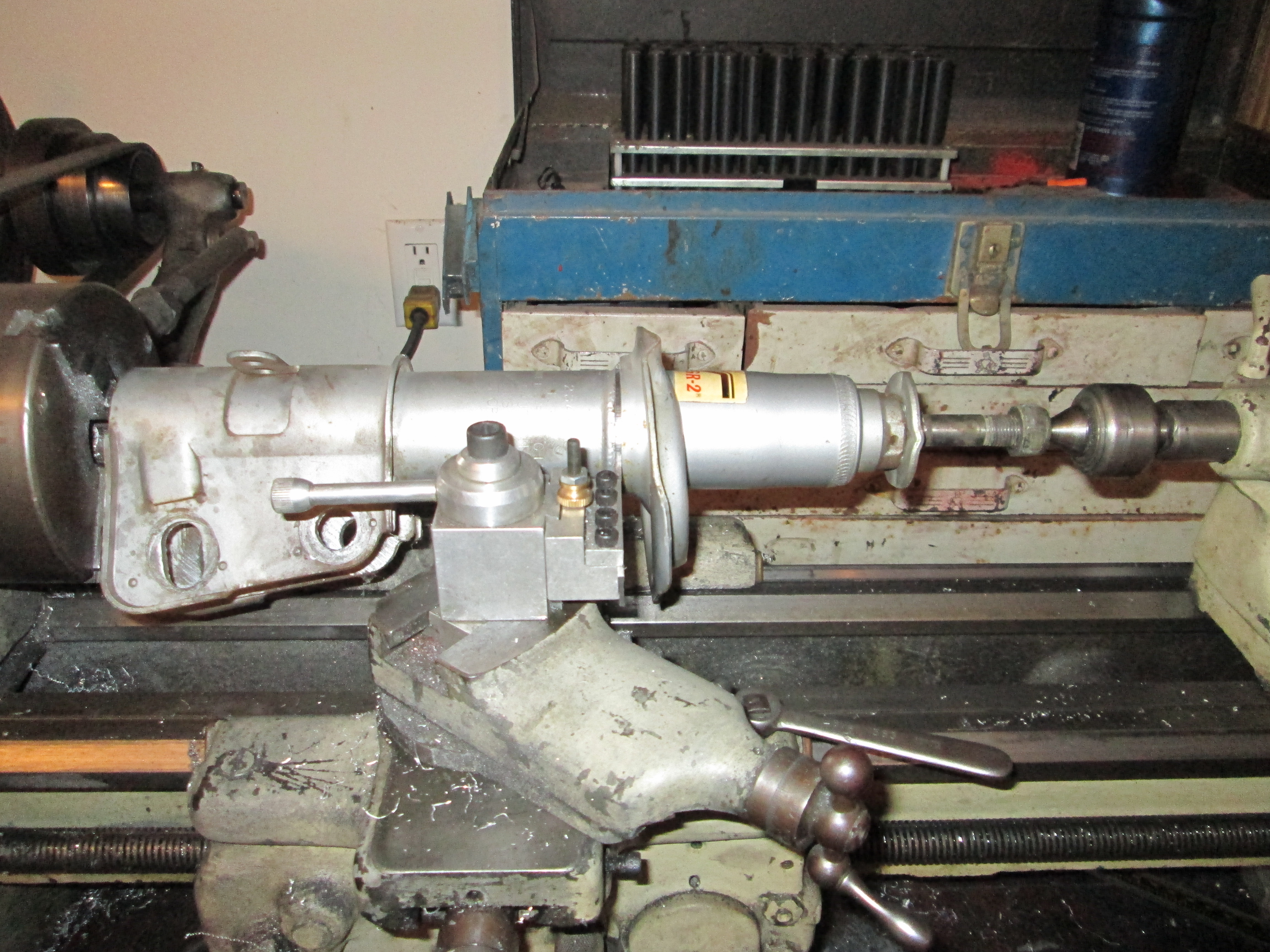
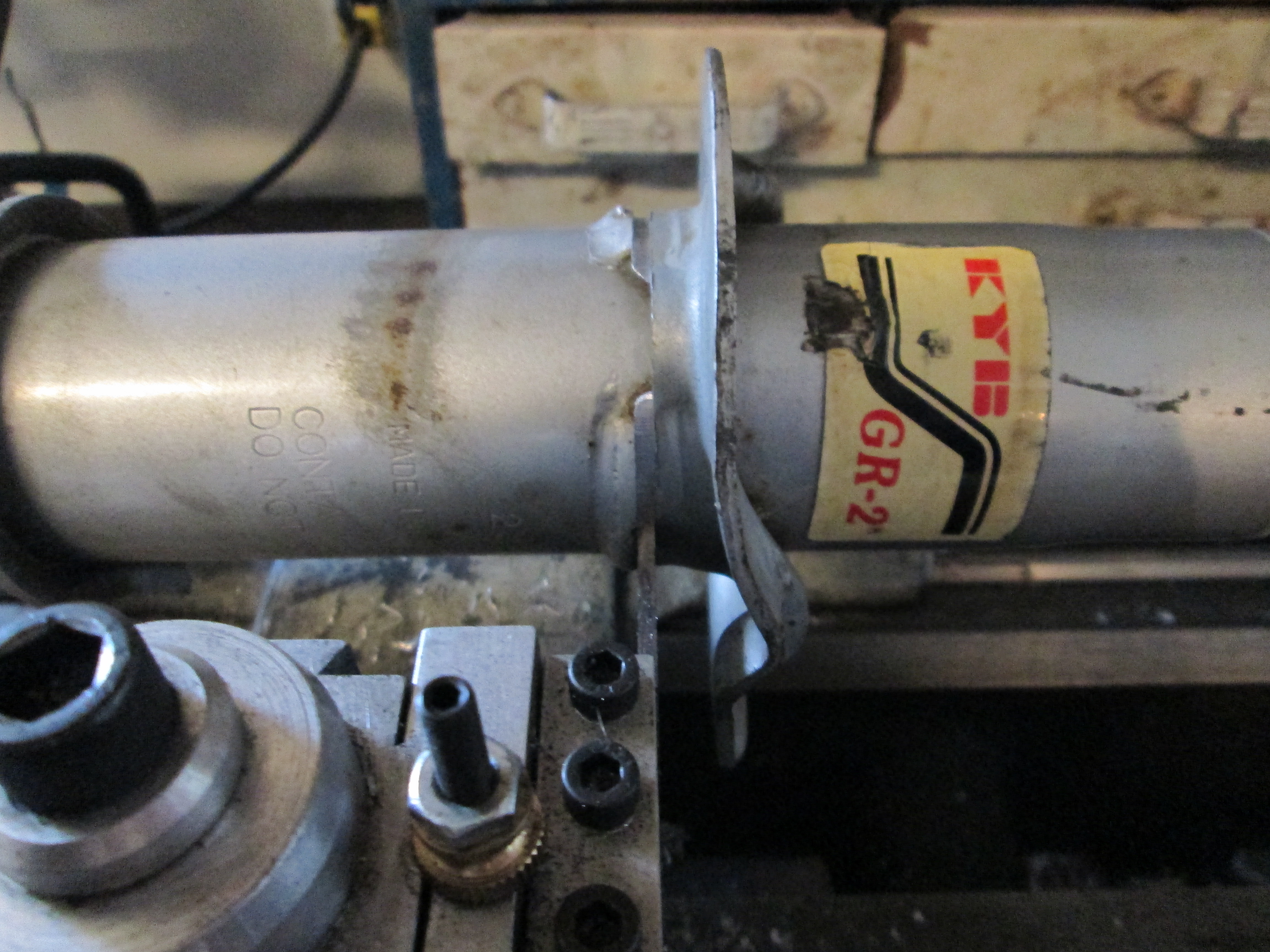
Finally got around to reworking the coolant pipes. The driver side one was an easy fix, just shorten the offset section by 1" and cut off the flange and reweld it in a new position.
Original setup:
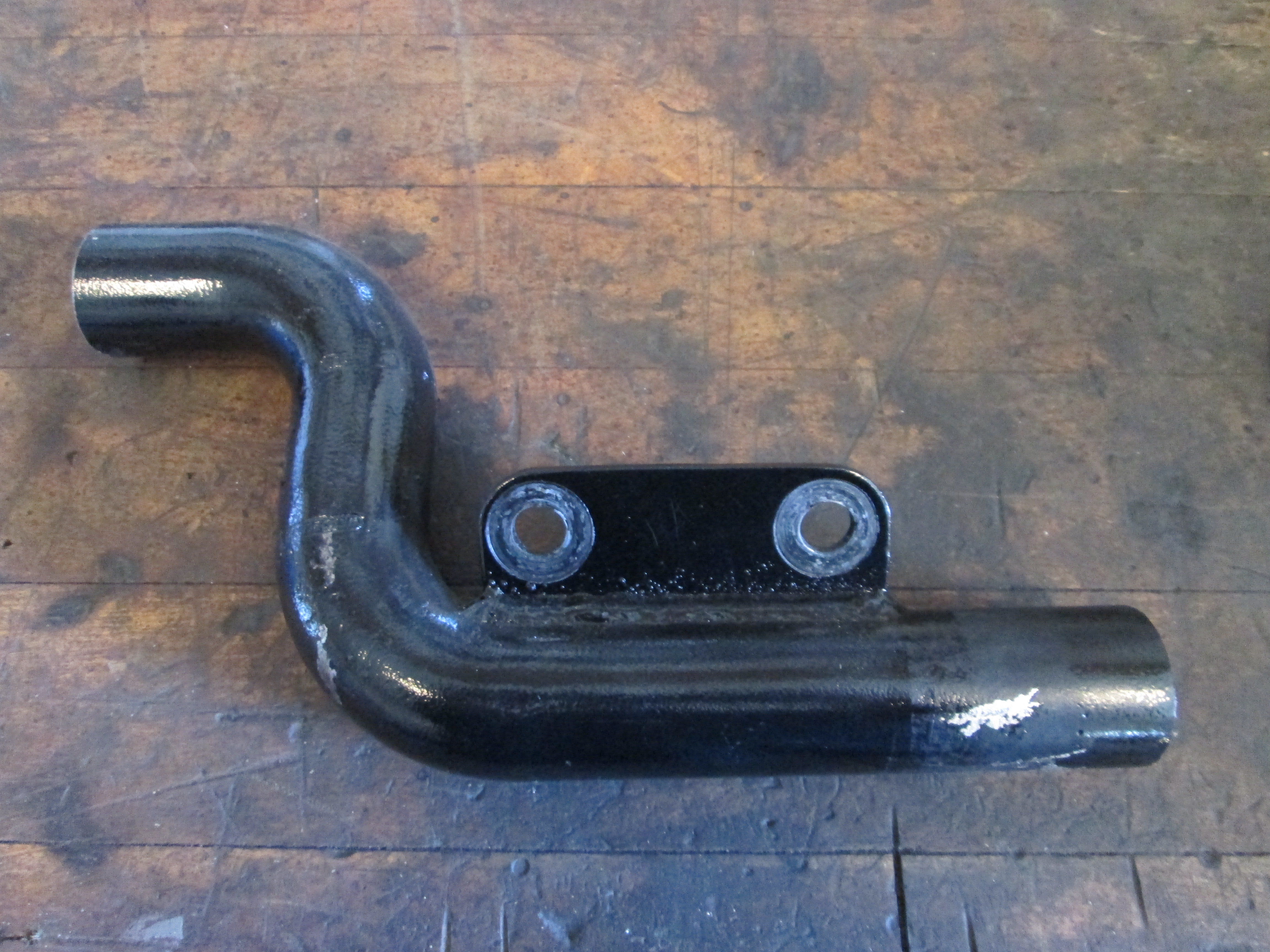
Modified one:
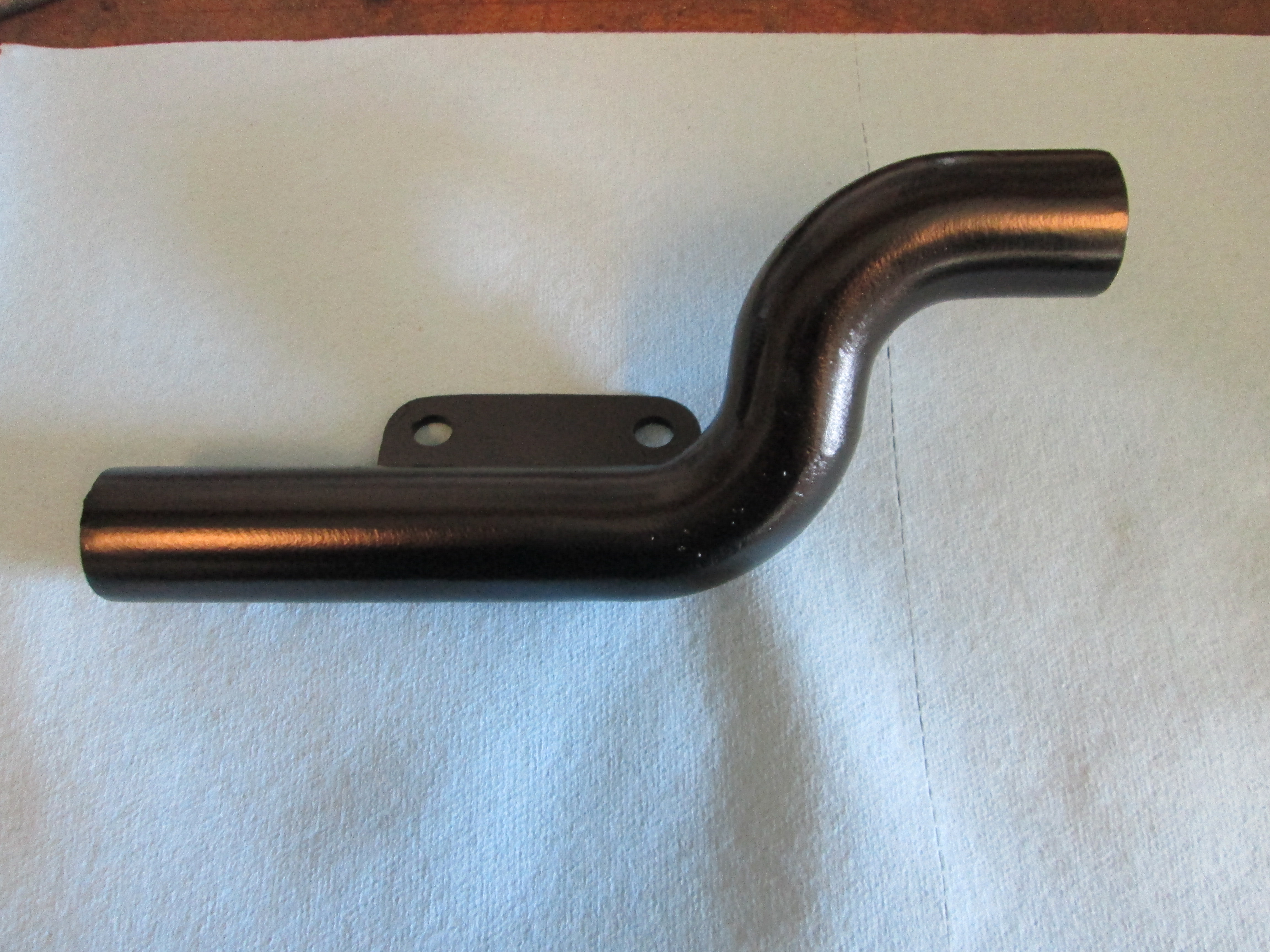
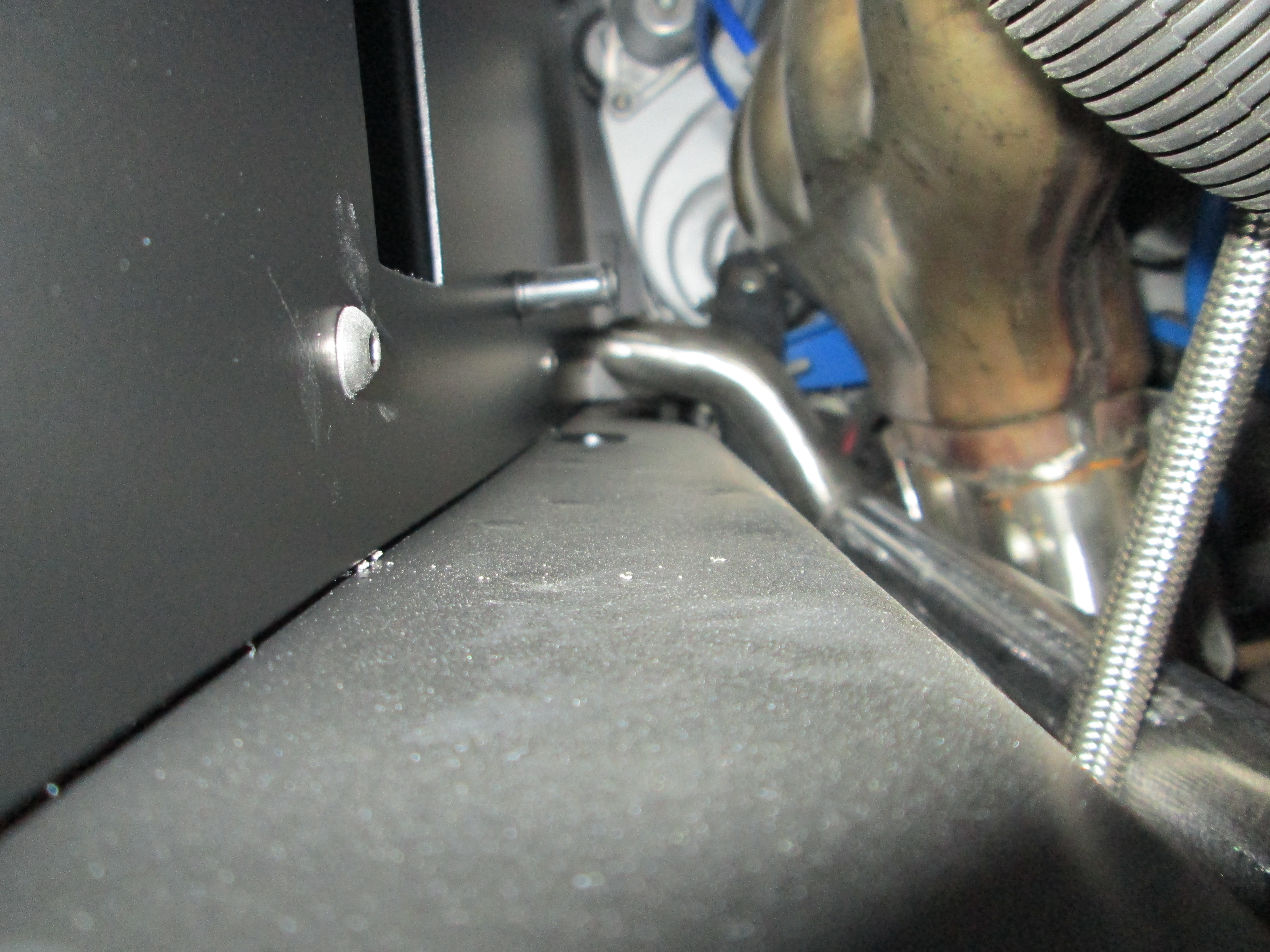
Here are a couple installed pictures. There is now about 3/16" between the tube and the PS front cradle mount tab:
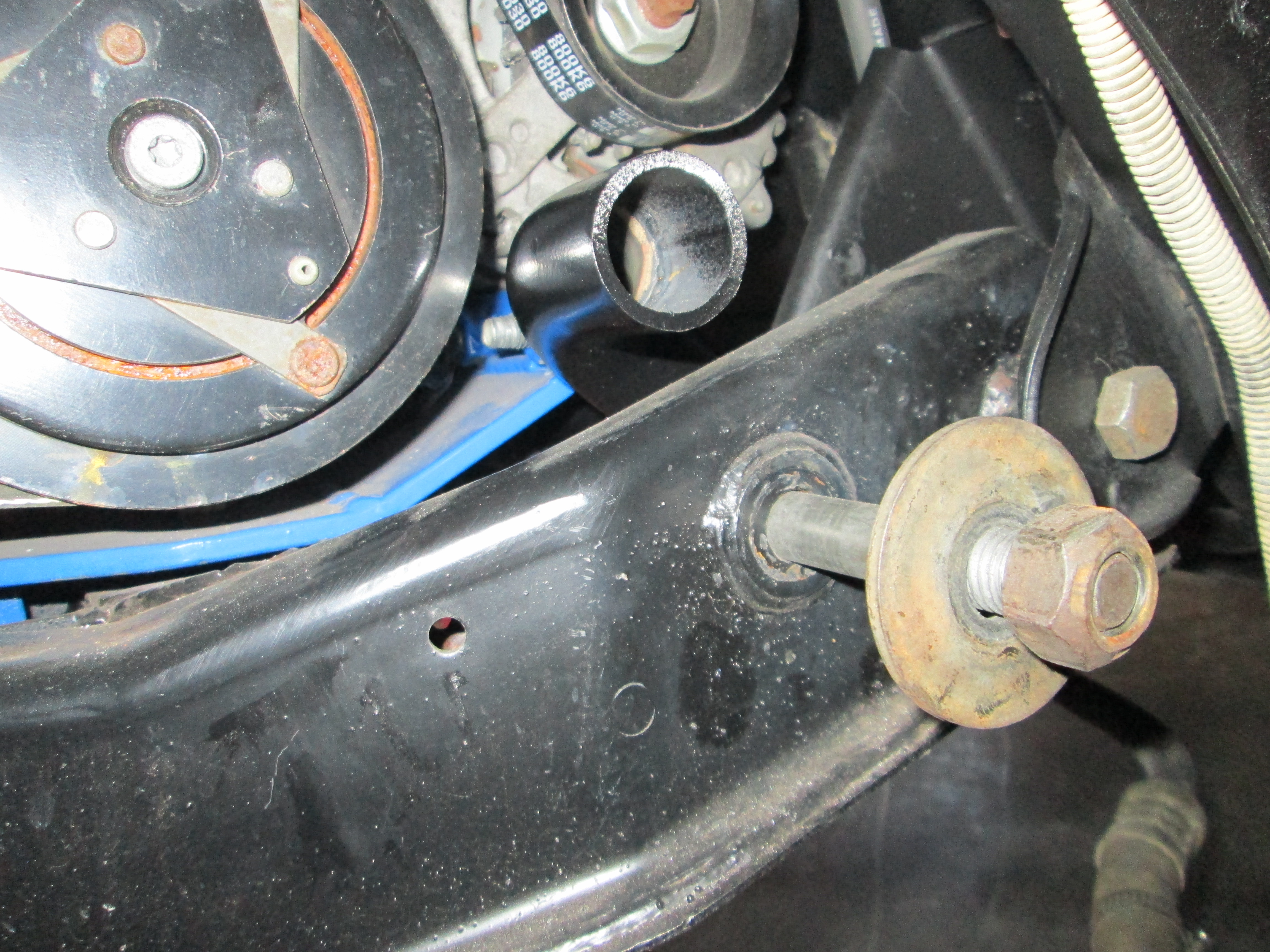
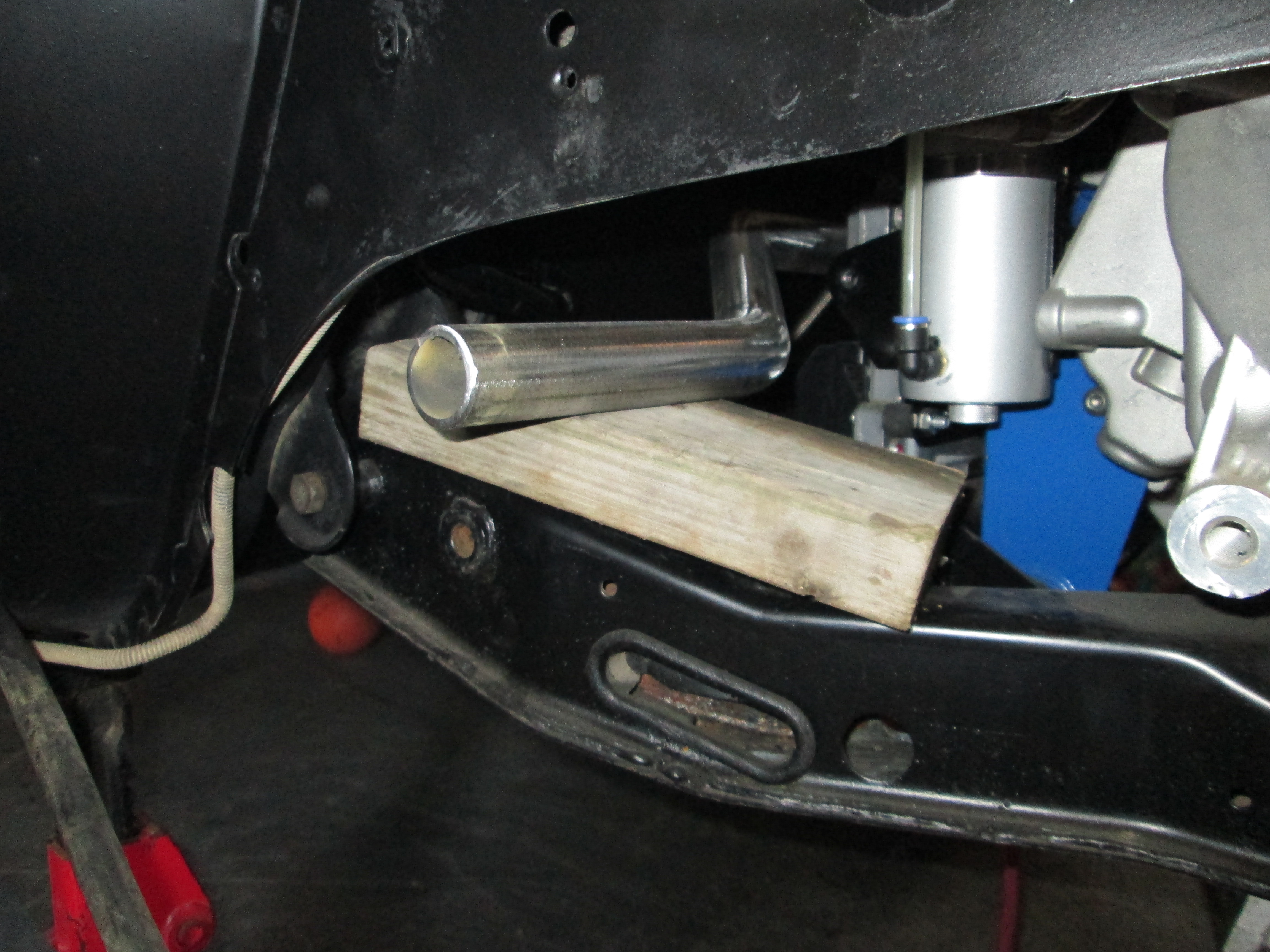
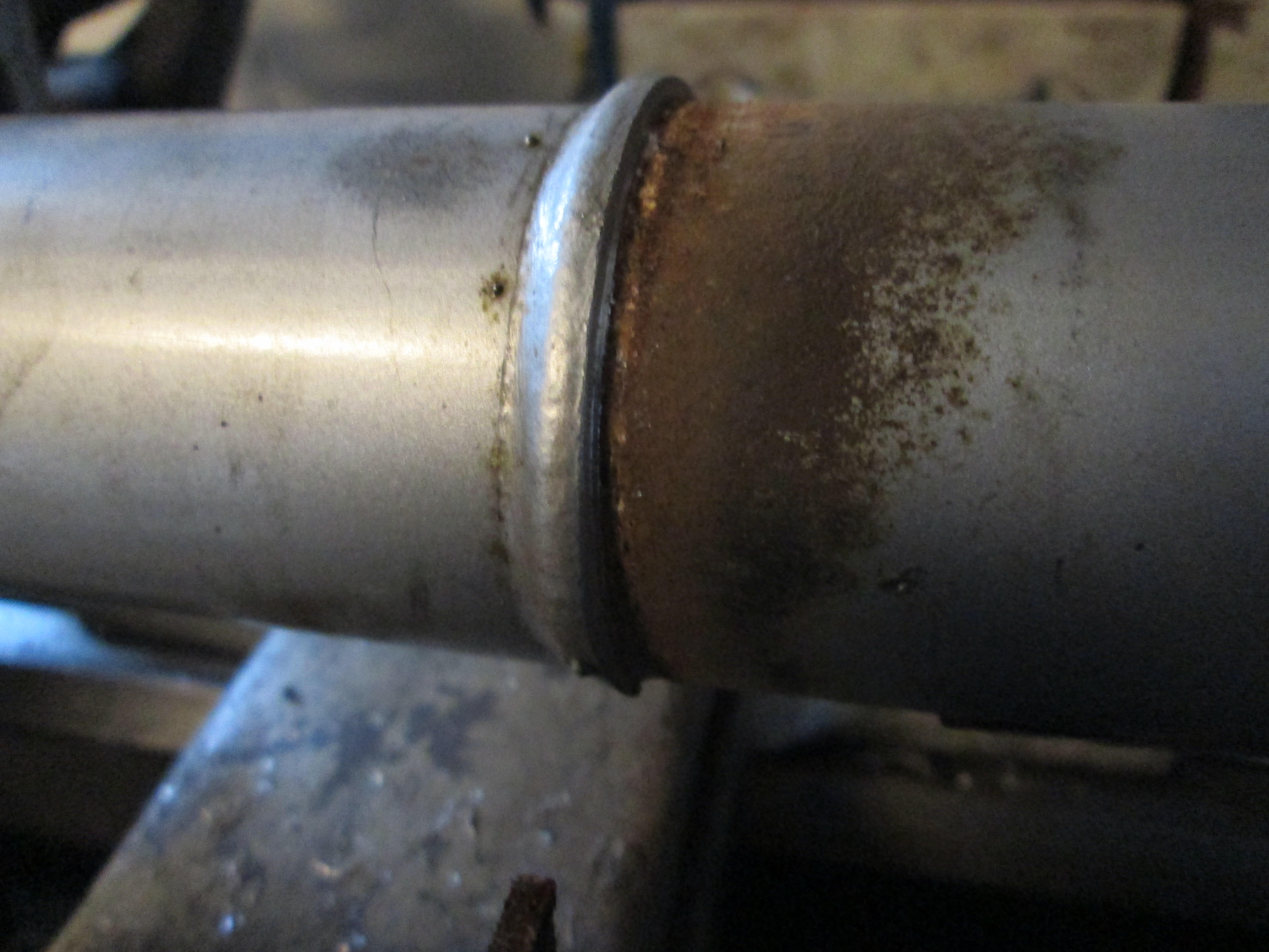
The DS tube was a pain... I ended up using the cradle tip method to remove/install this tube about 10 times during the fabrication process... but now it fits quite well and is nearly complete (just need to make the last mounting tab.
Original setup:
Modified one:
Here are a couple installed pictures. There is now about 3/16" between the tube and the PS front cradle mount tab:
The DS tube was a pain... I ended up using the cradle tip method to remove/install this tube about 10 times during the fabrication process... but now it fits quite well and is nearly complete (just need to make the last mounting tab.
01-20-2013, 09:09 PM
#103
Teching In
Join Date: Jan 2013
Posts: 16
Likes: 0
Received 0 Likes
on
0 Posts
This is probably one of the coolest build threads on here. I am pretty blown away by the fabrication and the insight into what parts to use. Very cool! What plug wires are those? I may steal your coil idea!
02-10-2013, 06:05 PM
#105
Finally back to working on this thing....
Fuel tank is back in and pumping gas. All the battery, ignition and ground feeds to the ECM/TCM checked out, so I hooked up HPtuners and did the initial download of the ecm/tcm calibration and worked up a base tune with the following changes...
VATS 1 and VATS 2: both set to Disable. This "should" turn off VATS
MAF Air Flow Frequency (Low): Compared to 07 Vette Table (same MAF I am using) and copied it, then confirmed the difference was 0. For MAF change
MAF Air Flow Frequency (High): Compared to 07 Vette Table and copied it, then confirmed the difference was 0. For MAF change
Injector Flow Rate vs. Pressure: Compared to 07 Vette Table and copied it, then confirmed the difference was 0. For Injector change
Tach Output- Tach Type. Originally was set for serial, the TBSS was Frequency so I changed it to Frequency. I "hope" this will enable the direct tach output like the TBSS has
ETC Scalar - Change to 4725 for 90mm TB
Effective Area Max - Changed to 8191 for 90mm TB
Effective Area Min - Changed to 0
Effective Area Min Fail - Changed to 5
RPM Limits - Extreme Cutoff - Changed to 6800
RPM Limits - Extreme Resume - Changed to 6720
Cutoff RPM vs. Gear - Changed all values to 6800
Cat Over Temp Protection: Disabled. I don't have a cat and this adds 25% fuel to protect the cat under certain conditions
Displacement On Demand: Disabled - it need to be off for all tuning. I will turn it back on at a later date
DoD RPM Thresholds - Min RPM: Changed to 1600 rpm. I only want it to work in 5th/6th gears between 45 and 80 mph
DoD RPM Thresholds - Max RPM: Changed to 2300 rpm. I only want it to work in 5th/6th gears between 45 and 80 mph
DoD Enable VSS: changed to 45 mph
DoD Disable vs PRNDL: D4 was 0, so I changed everything to 0 so DoD shouldn't care what the range switch says, even though the TCM is hard wired to show D4
DoD Disable vs Gear: 3rd gear and 4th gear were set to 0, so I changed 3rd gear to 1 and 5th and 6th gears to 0. No idea if this will work, but I changed it anyway
Engine Torque Management Spark: Disabled. I don't want any torque management
Engine Torque Management ETC: Disabled. Same reason
Transmission Diff Score: Disabled
Transmission Abuse Mode Torque Reductions vs. RPM: Set every value to 0 - no torque reductions
Transmission Abuse Mode Torque Reductions Duration vs. transmission temp: Set every value to 0 - no torque reductions
Starter Diag: Disabled. Using Fiero starter control
Clutch Interlock: Disabled. Using Fiero clutch pedal wiring
Number of Fans: Set to 1
Ignition off run time: set to 60 seconds. Reduced from 360 seconds due to my smaller battery
Speedometer - Tire Size: Set to 24.6
Speedometer - Gear Ratio: set to 3.55. F40 final drive ratio
Speedometer - VSS PP Rev: set to 78. # of teeth for F40 VSS
Speedometer - VSS PP Rev - Trans: set to 78. # of teeth for F40 VSS
Speedometer - VSS PP Mile: set to 63949
Speedometer - Revs per Dist (1 mile): Set to 819.86
Speedometer - Revs per Dist (1 mile) - trans: Set to 819.86
Speed Limiter (fuel cut off): Changed to 200mph
Speed Limiter 2 (fuel cut off): Changed to 200mph
The below Diagnostic Trouble Codes were turned off for missing components from the installation (Evap, Fuel Pressue, Post Cat O2 sensor, Cat, etc)
P0036 - HO2S Heater Control Circuit Bank 1 Sensor 2 - Turned off
P0054 - HO2S Heater Resistance Bank 1 Sensor 2 - Turned off
P0137 - HO2S Circuit Low Voltage Bank 1 Sensor 2 - Turned off
P0138 - HO2S Circuit High Voltage Bank 1 Sensor 2 - Turned off
P0140 - HO2S Circuit Insufficient Activity Bank 1 Sensor 2 - Turned off
P0141 - HO2S Heater Performance Bank 1 Sensor 2 - Turned off
P0420 - Catalyst System Low Efficiency - Turned off
P0422 - Evaporative Emission System Small Leak Detected - Turned off
P0443 - Evap Purge Solenoid Valve 1 Control CKT - Turned off
P0446 - Evap Vent Solenoid Valve Control System - Turned off
P0449 - Evaporative Emission Vent Solenoid Control Circuit - Turned off
P0451 - Evaporative Emission Control System Pressure Sensor Range - Turned off
P0452 - Fuel Tank Pessure Sensor Circuit Low Voltage - Turned off
P0453 - Fuel Tank Pessure Sensor Circuit High Voltage - Turned off
P0454 - Evaporative Emission Control System Pressure Sensor Intermittent - Turned off
P0455 - Evaporative Emission System Leak Detected - Turned off
P0461 - Fuel Level Sensor Performance - Turned off
P0462 - Fuel Level Sensor Circuit Low Voltage - Turned off
P0463 - Fuel Level Sensor Circuit Low Voltage - Turned off
P0464 - Fuel Level Sensor Circuit Intermittent - Turned off
P0481 - Cooling Fan Relay 2 Control - Turned off
P0496 - Evaporative Emission System High Purge Flow - Turned off
P2544 - Torque Management Request Input Signal A - Turned off
P2A01 - O2 Sensor Circuit Range/Performance Bank 1 Sensor 2 - Turned off
Once all these changed were saved, I did a Write Entire to the ECM/TCM.
The throttle body wasn't working and I figured out there is a naming difference between the LS4 and LS2. The TP Sensor 1 and TP Sensor 2 wires have to be switched for it to work. Once I switched them the engine fired up:
Here is the first start with a nasty lope... I set off the garage smoke alarms...
Here is how it idles after a couple of throttle blips... I rattled the glasses in the kitchen on this one. I need to work on the ETC settings to close the throttle faster.
Here are a couple of pictures of the engine bay:

I am please that the mini battery has been able to spin this engine quite a bit during the initial no start debug stage before actually starting it.
Fuel tank is back in and pumping gas. All the battery, ignition and ground feeds to the ECM/TCM checked out, so I hooked up HPtuners and did the initial download of the ecm/tcm calibration and worked up a base tune with the following changes...
VATS 1 and VATS 2: both set to Disable. This "should" turn off VATS
MAF Air Flow Frequency (Low): Compared to 07 Vette Table (same MAF I am using) and copied it, then confirmed the difference was 0. For MAF change
MAF Air Flow Frequency (High): Compared to 07 Vette Table and copied it, then confirmed the difference was 0. For MAF change
Injector Flow Rate vs. Pressure: Compared to 07 Vette Table and copied it, then confirmed the difference was 0. For Injector change
Tach Output- Tach Type. Originally was set for serial, the TBSS was Frequency so I changed it to Frequency. I "hope" this will enable the direct tach output like the TBSS has
ETC Scalar - Change to 4725 for 90mm TB
Effective Area Max - Changed to 8191 for 90mm TB
Effective Area Min - Changed to 0
Effective Area Min Fail - Changed to 5
RPM Limits - Extreme Cutoff - Changed to 6800
RPM Limits - Extreme Resume - Changed to 6720
Cutoff RPM vs. Gear - Changed all values to 6800
Cat Over Temp Protection: Disabled. I don't have a cat and this adds 25% fuel to protect the cat under certain conditions
Displacement On Demand: Disabled - it need to be off for all tuning. I will turn it back on at a later date
DoD RPM Thresholds - Min RPM: Changed to 1600 rpm. I only want it to work in 5th/6th gears between 45 and 80 mph
DoD RPM Thresholds - Max RPM: Changed to 2300 rpm. I only want it to work in 5th/6th gears between 45 and 80 mph
DoD Enable VSS: changed to 45 mph
DoD Disable vs PRNDL: D4 was 0, so I changed everything to 0 so DoD shouldn't care what the range switch says, even though the TCM is hard wired to show D4
DoD Disable vs Gear: 3rd gear and 4th gear were set to 0, so I changed 3rd gear to 1 and 5th and 6th gears to 0. No idea if this will work, but I changed it anyway
Engine Torque Management Spark: Disabled. I don't want any torque management
Engine Torque Management ETC: Disabled. Same reason
Transmission Diff Score: Disabled
Transmission Abuse Mode Torque Reductions vs. RPM: Set every value to 0 - no torque reductions
Transmission Abuse Mode Torque Reductions Duration vs. transmission temp: Set every value to 0 - no torque reductions
Starter Diag: Disabled. Using Fiero starter control
Clutch Interlock: Disabled. Using Fiero clutch pedal wiring
Number of Fans: Set to 1
Ignition off run time: set to 60 seconds. Reduced from 360 seconds due to my smaller battery
Speedometer - Tire Size: Set to 24.6
Speedometer - Gear Ratio: set to 3.55. F40 final drive ratio
Speedometer - VSS PP Rev: set to 78. # of teeth for F40 VSS
Speedometer - VSS PP Rev - Trans: set to 78. # of teeth for F40 VSS
Speedometer - VSS PP Mile: set to 63949
Speedometer - Revs per Dist (1 mile): Set to 819.86
Speedometer - Revs per Dist (1 mile) - trans: Set to 819.86
Speed Limiter (fuel cut off): Changed to 200mph
Speed Limiter 2 (fuel cut off): Changed to 200mph
The below Diagnostic Trouble Codes were turned off for missing components from the installation (Evap, Fuel Pressue, Post Cat O2 sensor, Cat, etc)
P0036 - HO2S Heater Control Circuit Bank 1 Sensor 2 - Turned off
P0054 - HO2S Heater Resistance Bank 1 Sensor 2 - Turned off
P0137 - HO2S Circuit Low Voltage Bank 1 Sensor 2 - Turned off
P0138 - HO2S Circuit High Voltage Bank 1 Sensor 2 - Turned off
P0140 - HO2S Circuit Insufficient Activity Bank 1 Sensor 2 - Turned off
P0141 - HO2S Heater Performance Bank 1 Sensor 2 - Turned off
P0420 - Catalyst System Low Efficiency - Turned off
P0422 - Evaporative Emission System Small Leak Detected - Turned off
P0443 - Evap Purge Solenoid Valve 1 Control CKT - Turned off
P0446 - Evap Vent Solenoid Valve Control System - Turned off
P0449 - Evaporative Emission Vent Solenoid Control Circuit - Turned off
P0451 - Evaporative Emission Control System Pressure Sensor Range - Turned off
P0452 - Fuel Tank Pessure Sensor Circuit Low Voltage - Turned off
P0453 - Fuel Tank Pessure Sensor Circuit High Voltage - Turned off
P0454 - Evaporative Emission Control System Pressure Sensor Intermittent - Turned off
P0455 - Evaporative Emission System Leak Detected - Turned off
P0461 - Fuel Level Sensor Performance - Turned off
P0462 - Fuel Level Sensor Circuit Low Voltage - Turned off
P0463 - Fuel Level Sensor Circuit Low Voltage - Turned off
P0464 - Fuel Level Sensor Circuit Intermittent - Turned off
P0481 - Cooling Fan Relay 2 Control - Turned off
P0496 - Evaporative Emission System High Purge Flow - Turned off
P2544 - Torque Management Request Input Signal A - Turned off
P2A01 - O2 Sensor Circuit Range/Performance Bank 1 Sensor 2 - Turned off
Once all these changed were saved, I did a Write Entire to the ECM/TCM.
The throttle body wasn't working and I figured out there is a naming difference between the LS4 and LS2. The TP Sensor 1 and TP Sensor 2 wires have to be switched for it to work. Once I switched them the engine fired up:
Here is the first start with a nasty lope... I set off the garage smoke alarms...
Here is how it idles after a couple of throttle blips... I rattled the glasses in the kitchen on this one. I need to work on the ETC settings to close the throttle faster.
Here are a couple of pictures of the engine bay:
I am please that the mini battery has been able to spin this engine quite a bit during the initial no start debug stage before actually starting it.
02-17-2013, 05:50 PM
#107
If you ignore the squeal (new belt slipping or bad bearing in alternator or water pump), here is what it sounds like slowly revving to 6250 rpm...
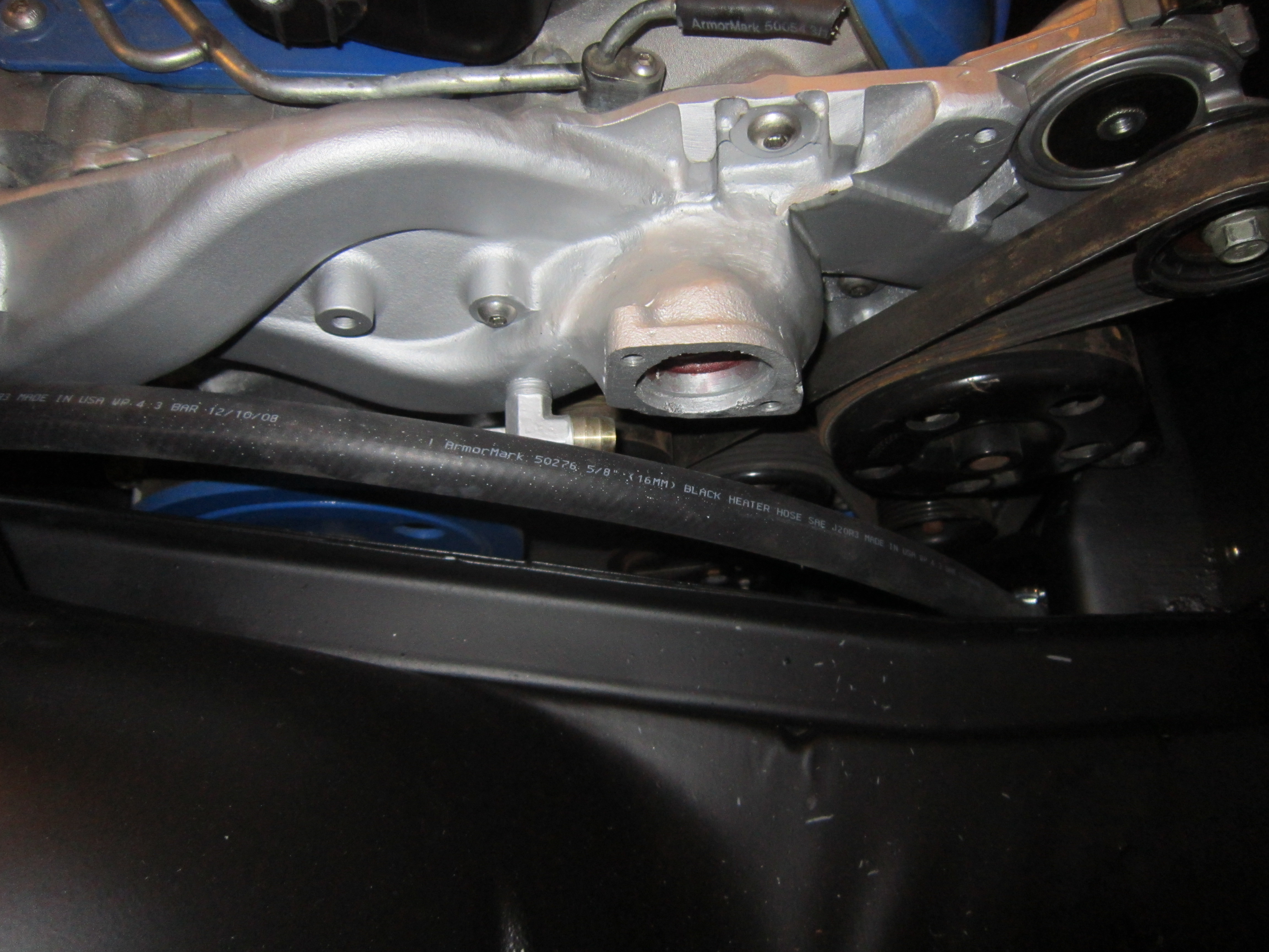
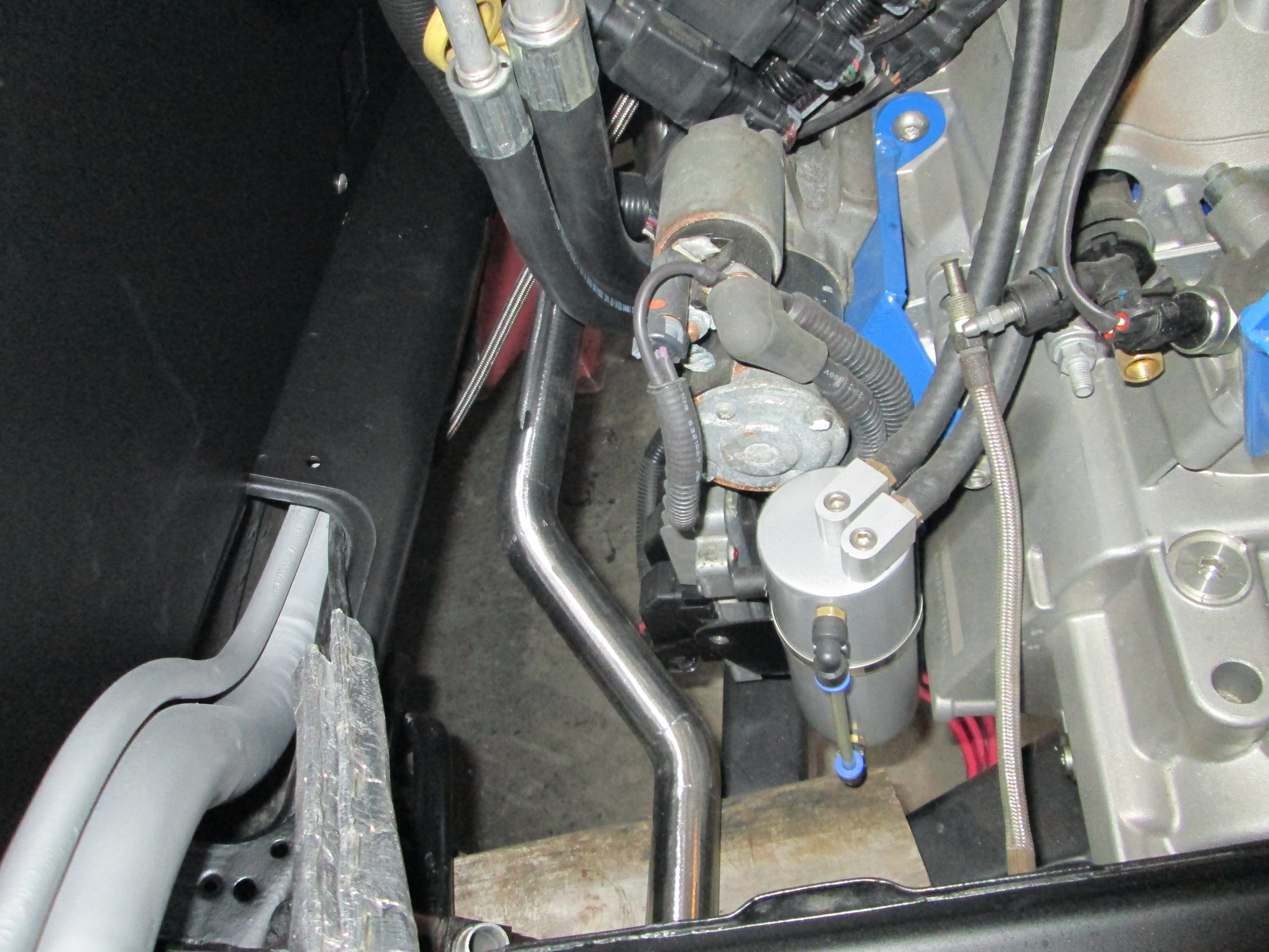
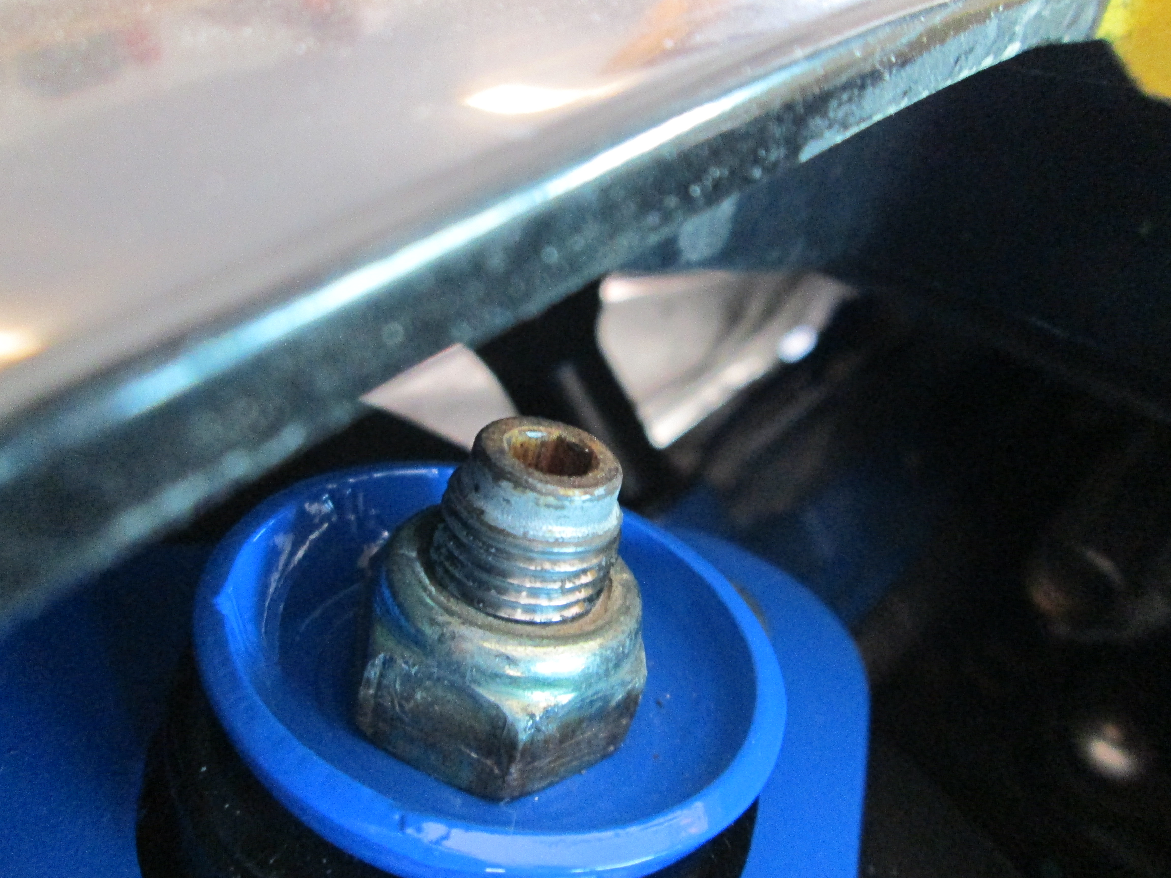
If you are working on an LS4, you can't use the fel-pro oil bypass gasket or any aftermarket bypass plate... because they are different:
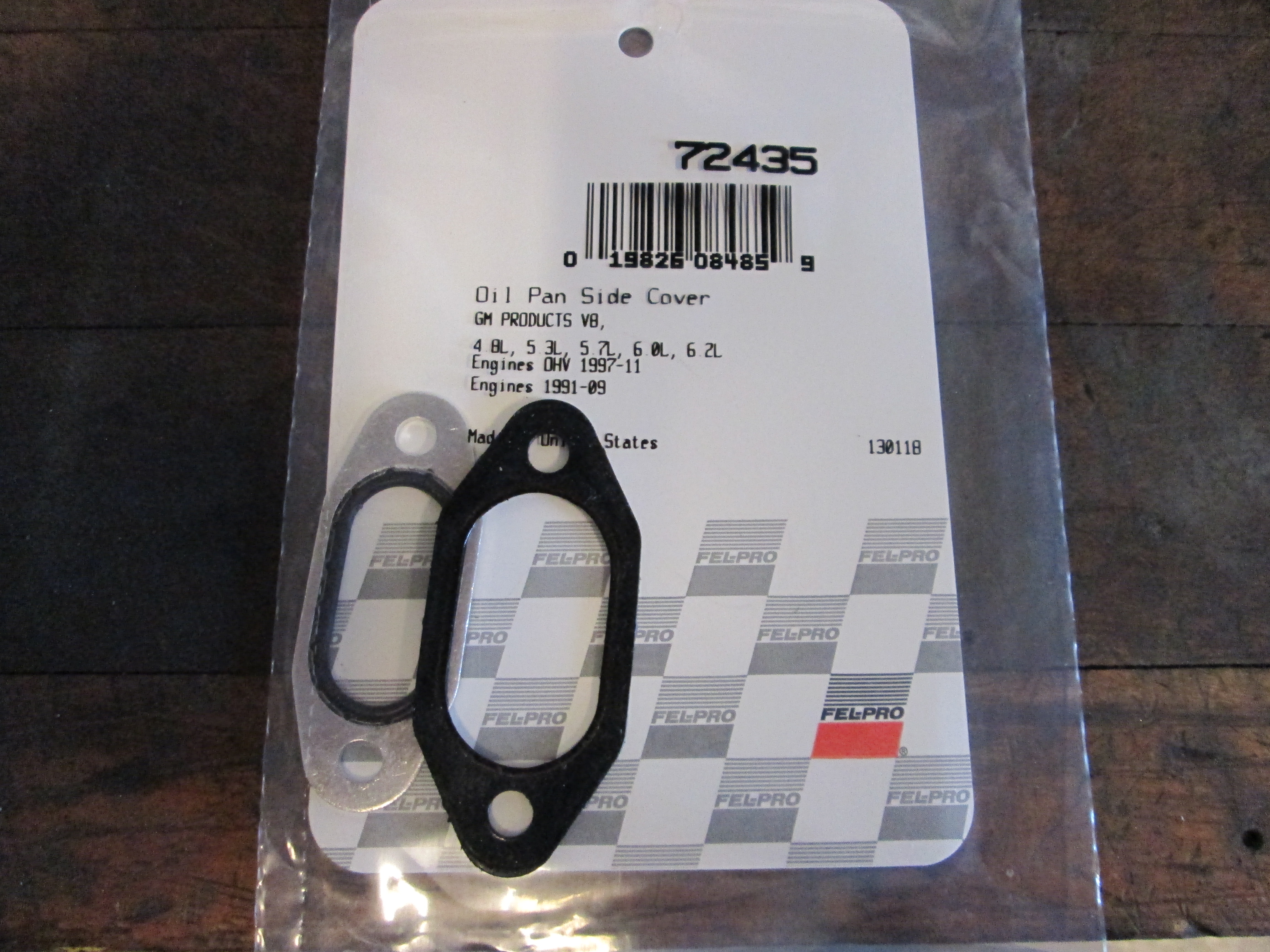
I had a leak at this plate from removing it w/o replacing the gasket with new. Since this fel-pro one didn't fit I went ahead and cut my own using the cover plate at a pattern. No more leaks.
Put the coolant in and was able to idle the engine for about 30 minutes and lifter chatter calmed down
Got a new code the other day P1915 - transmission range not in P/N at engine start. Since I wired the TCM to see D4 all the time, this isn't a surprise. However, this DCT isn't listed under the engine codes and is a TCM DCT. The issue is currently HP Tuners doesn't have any TCM DCT's listed, so I can't turn this one off.
I wired the TCM to think it was in D all the time because I didn't want to hassle with a bunch of switches to make it change from P/N to D, but since I can't turn off P1915, I took another look:

There are 4 Range signals, A, B, C, & P and they are either open or wired to ground to determine the range selection.
Signal P is always open for every gear and how it is currently wired, so no change needed.
Signal A & B are at the same state for N and D, so no change is needed.
Signal C needs to be Open for N and Grounded for D. It is currently grounded and I need a way to break the circuit by pressing the clutch pedal. The Fiero cruise switch on the clutch pedal has a 2 terminal end that has continuity between the terminals when the clutch pedal is released and it breaks the signal when the clutch pedal is pressed. By wiring one terminal to ground and running a wire from the 2nd one back to the TCM for Range Signal C, the TCM will see N when the clutch is pressed/started and D at all other times.
This switch will also allow me to play with "no lift shift"
Here the clutch swith is installed on the clutch pedal:
Then I ran the wires to the clutch pedal. If you look closely I used some 5/8" hose and a wire tie to hold the switch in place. One wire terminated at the ground screw from the front harness, the other one traveled along the vacuum tube and was connected to the TCM (after yet another connector was added). This should eliminate the P1915 code.
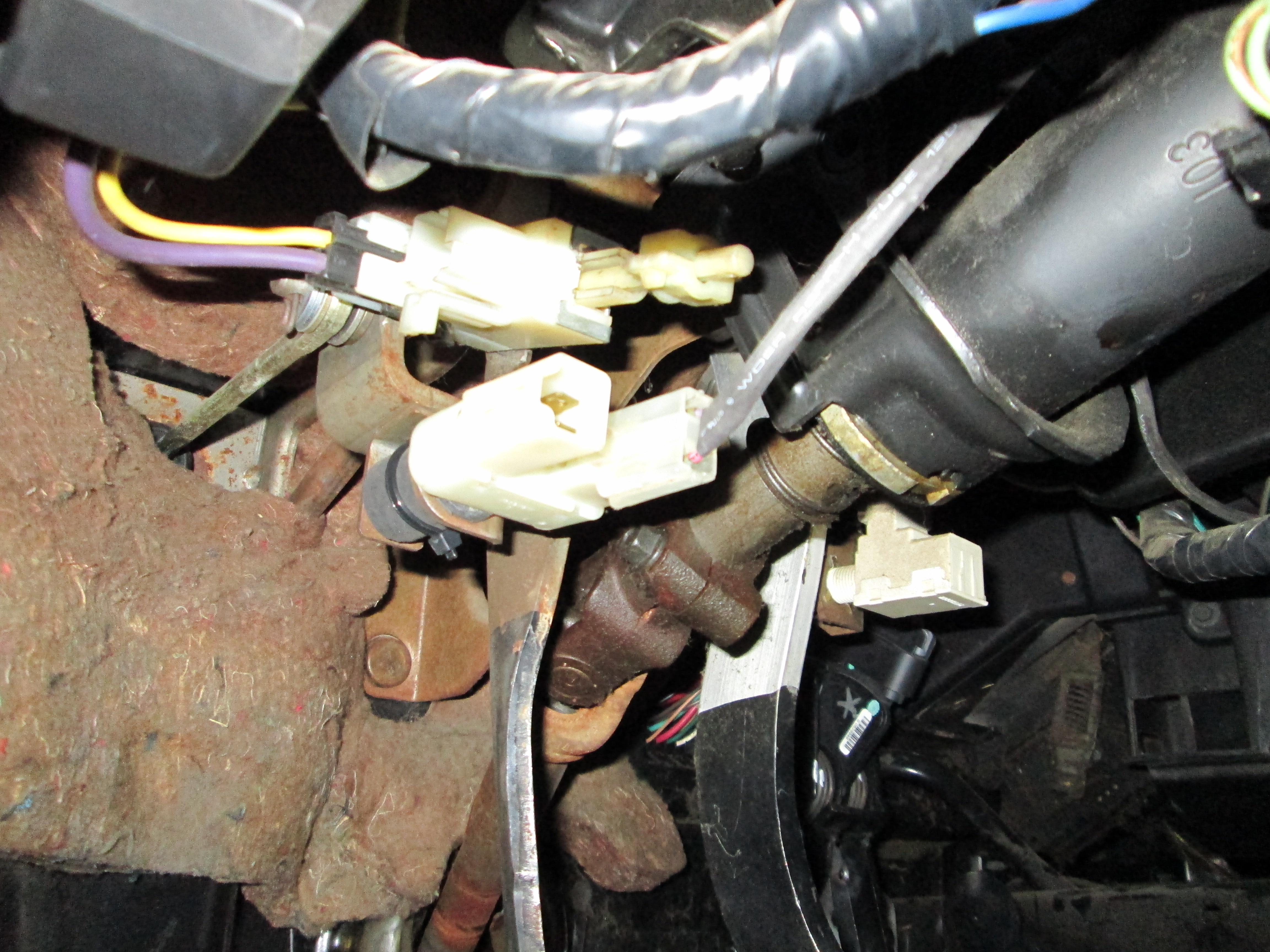
Since the E67 does not have an EGR, I am routing the 0-5V signal from the wideband to the Fuel Tank Pressure input on the ECM. This sensor input is for the EVAP system, and isn't being used in my swap.
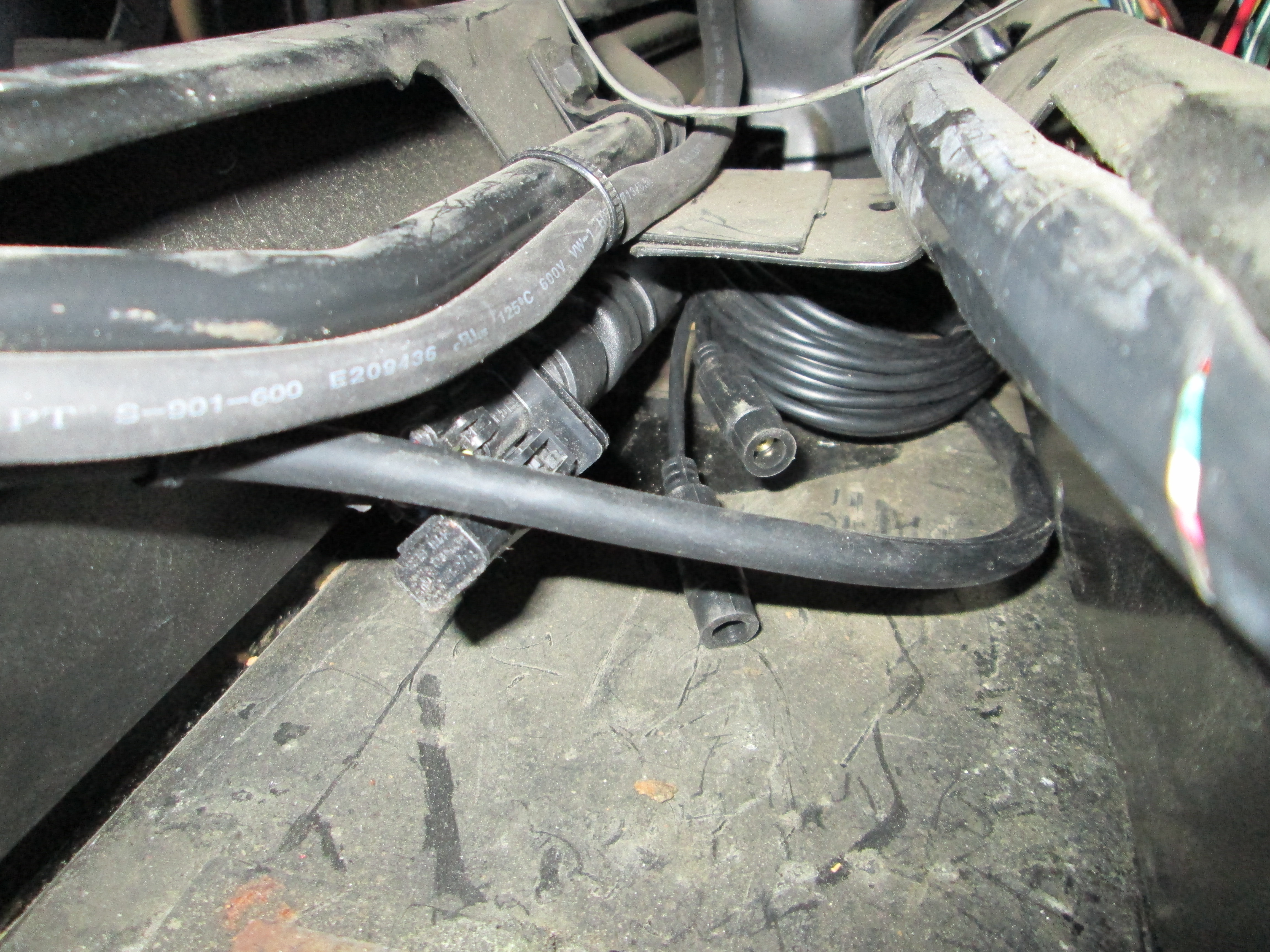
When I ran the rear portion of the wideband harness, I added a connector close to the sensor and extended the wires so I could get the controller out of the engine bay. Since there is no throttle cable, I figured the space in front of the shifter was a good place for the wide band controller and its wires. You can also see the DBW pedal harness running along the vacuum tube:
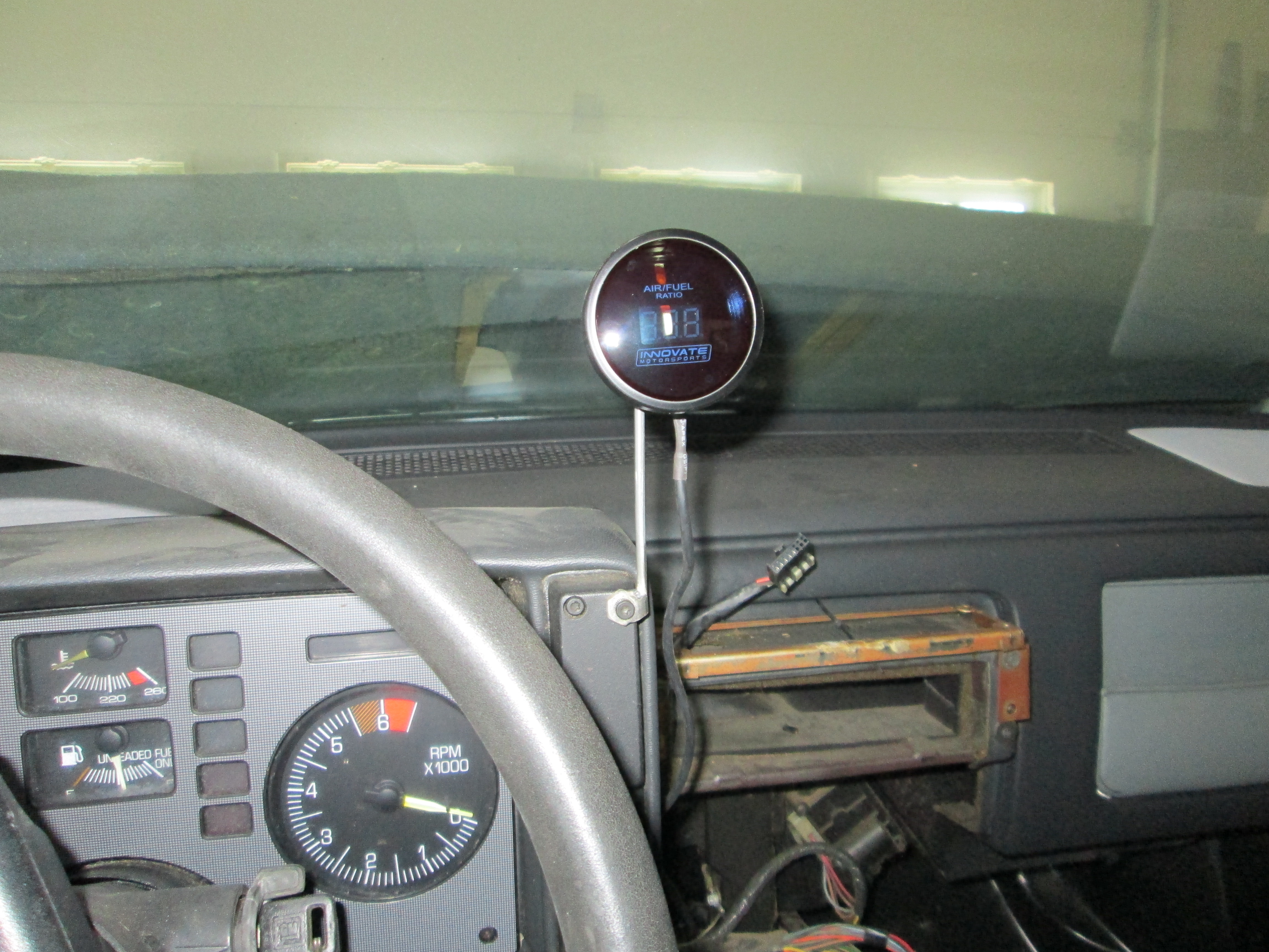
Here is a temp mount for the wideband gauge (haven't decided exactly where I will put this, but I like it here for tuning). Once this was mounted, I went ahead and calibrated the wideband in open air, then reinstalled it:
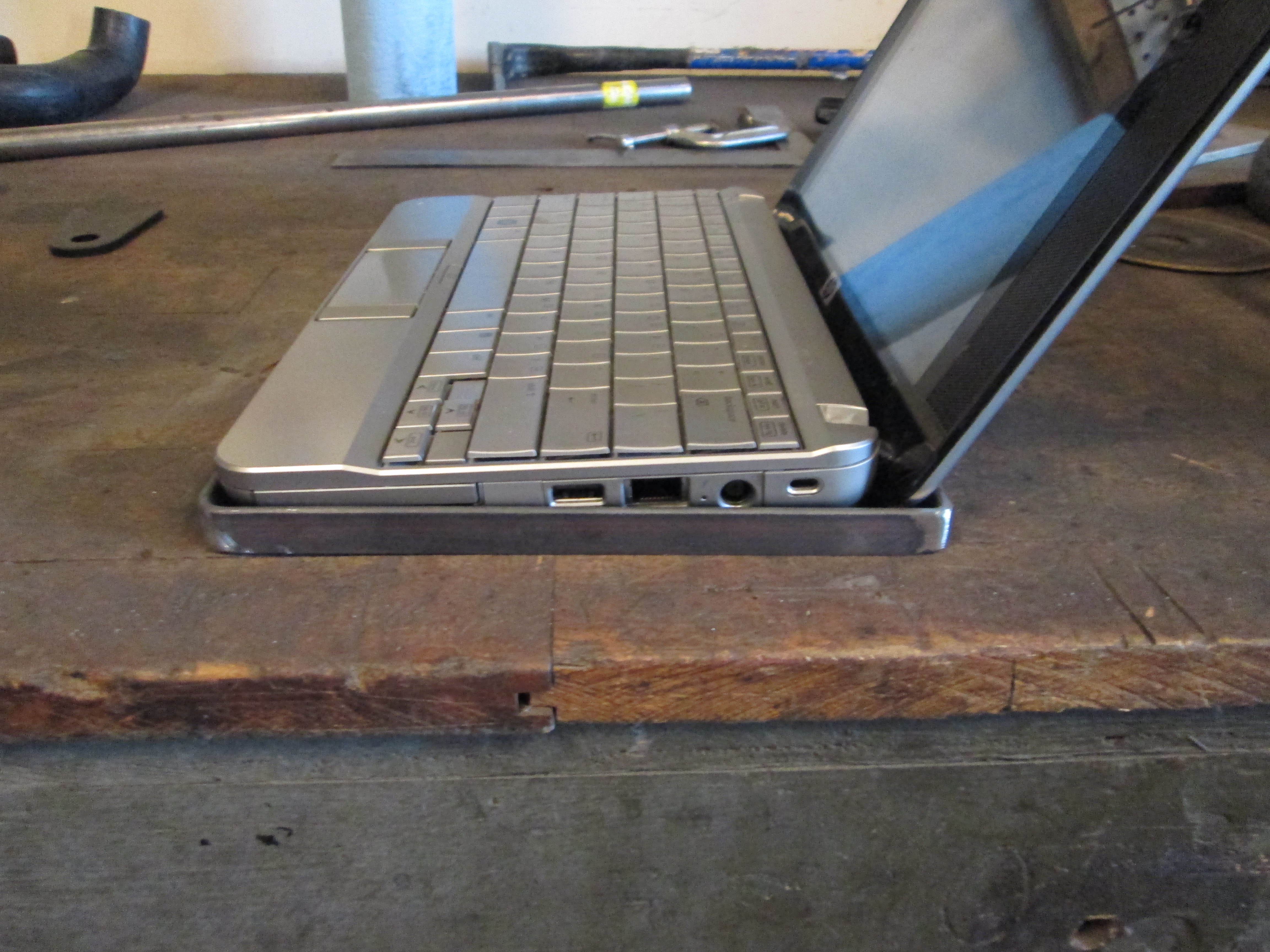
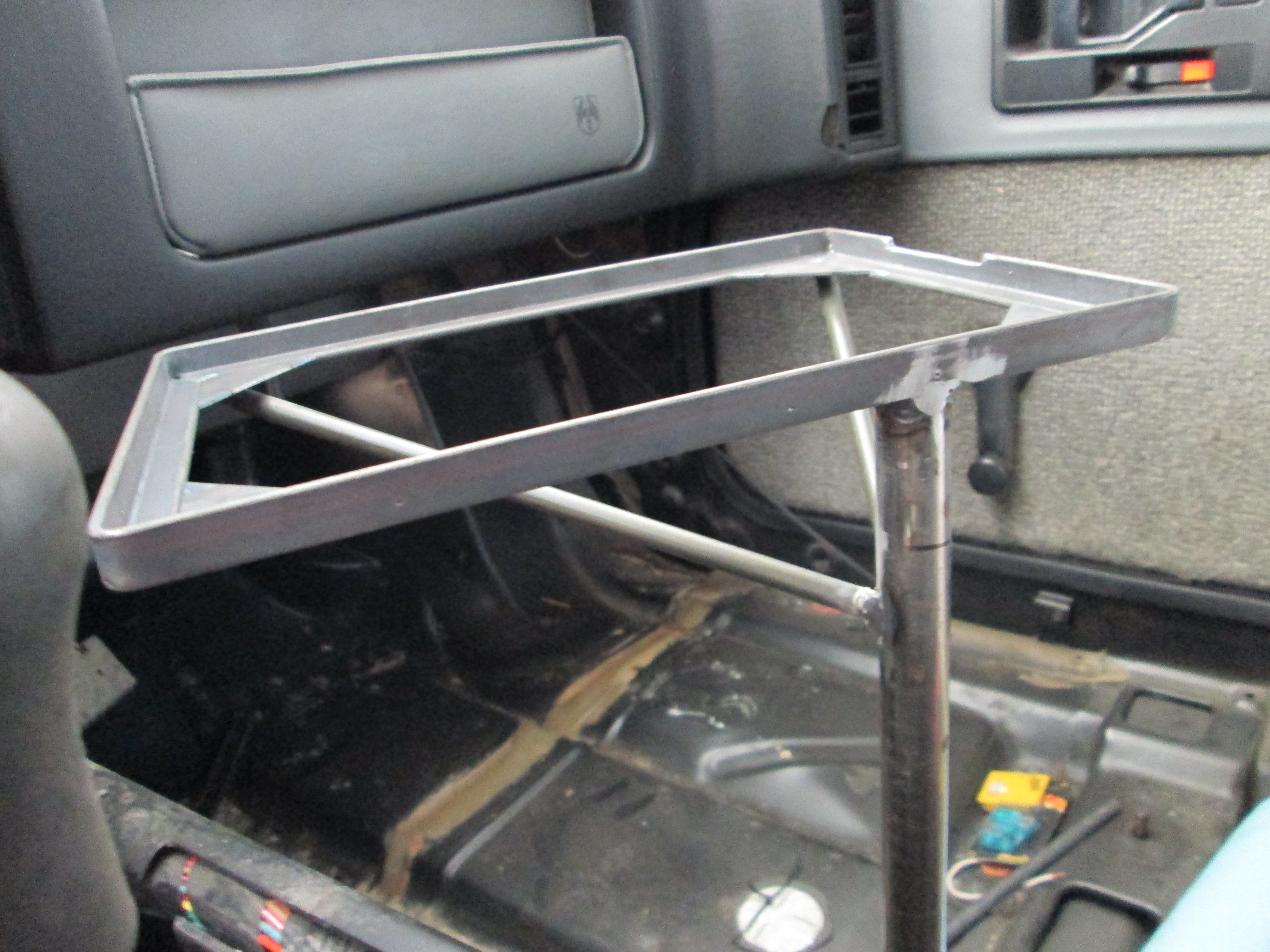
I decided to make a laptop stand for the car (the corner pads support the rubber feet on the laptop):
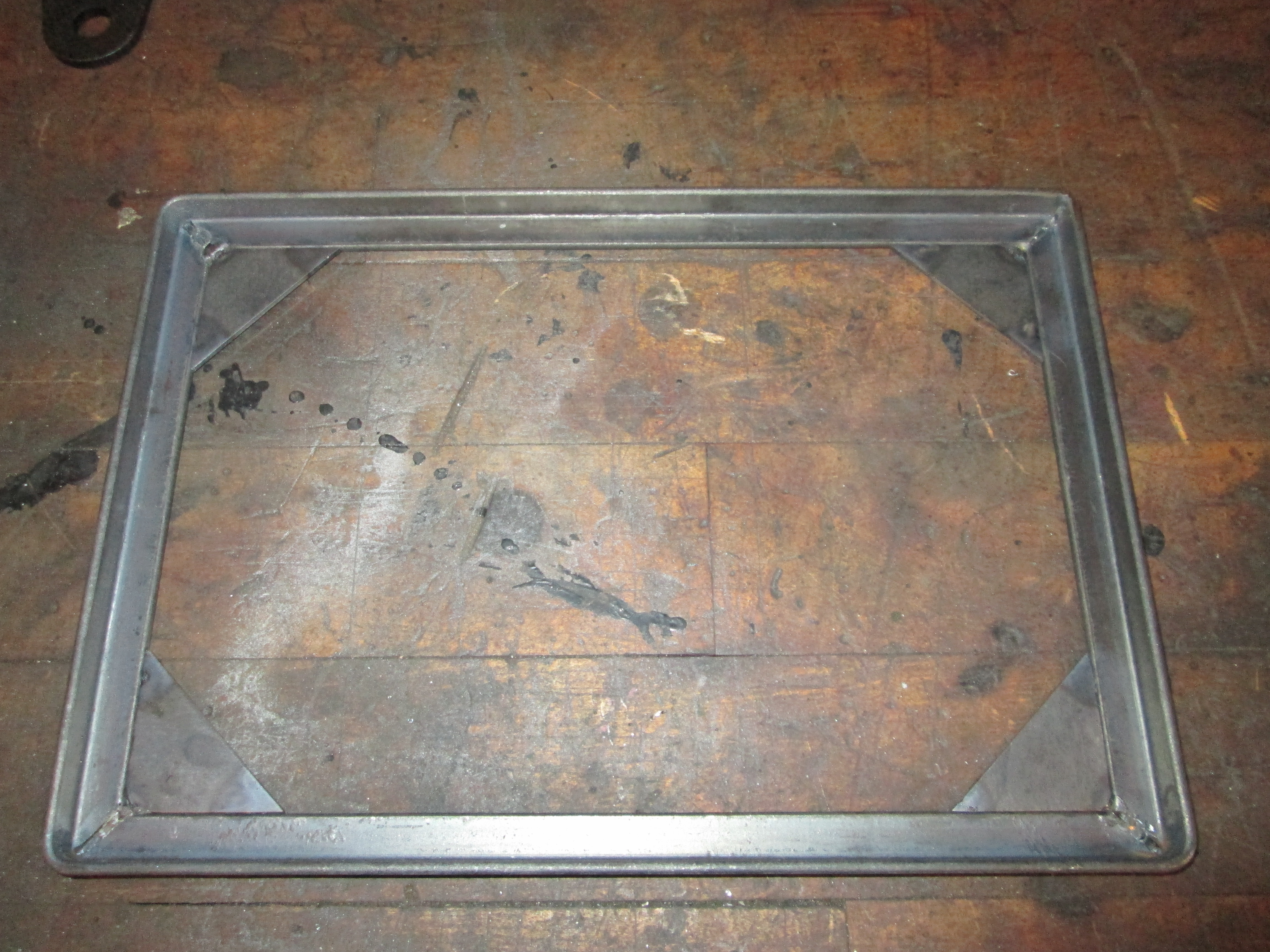
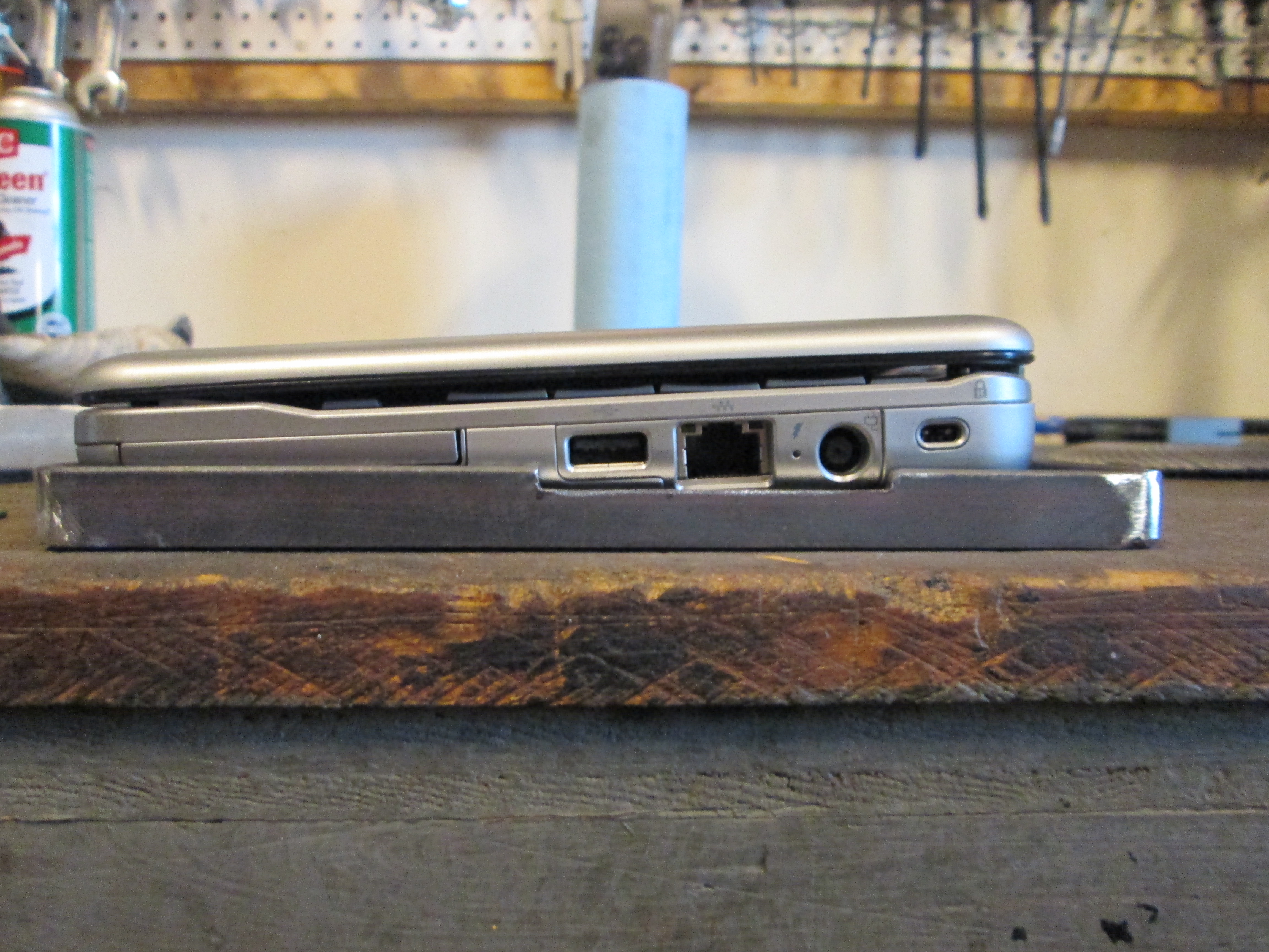
Notice the stand is a little deeper than needed, mainly so the top can be fully open (it drops down in the rear when open). You can also see I need to add a notch for the USB and the power cord.
Notch complete:
I am taking vacation on W, TH and F this week so I will have a long 5 day weekend to make more progress.
If you are working on an LS4, you can't use the fel-pro oil bypass gasket or any aftermarket bypass plate... because they are different:
I had a leak at this plate from removing it w/o replacing the gasket with new. Since this fel-pro one didn't fit I went ahead and cut my own using the cover plate at a pattern. No more leaks.
Put the coolant in and was able to idle the engine for about 30 minutes and lifter chatter calmed down
Got a new code the other day P1915 - transmission range not in P/N at engine start. Since I wired the TCM to see D4 all the time, this isn't a surprise. However, this DCT isn't listed under the engine codes and is a TCM DCT. The issue is currently HP Tuners doesn't have any TCM DCT's listed, so I can't turn this one off.
I wired the TCM to think it was in D all the time because I didn't want to hassle with a bunch of switches to make it change from P/N to D, but since I can't turn off P1915, I took another look:
There are 4 Range signals, A, B, C, & P and they are either open or wired to ground to determine the range selection.
Signal P is always open for every gear and how it is currently wired, so no change needed.
Signal A & B are at the same state for N and D, so no change is needed.
Signal C needs to be Open for N and Grounded for D. It is currently grounded and I need a way to break the circuit by pressing the clutch pedal. The Fiero cruise switch on the clutch pedal has a 2 terminal end that has continuity between the terminals when the clutch pedal is released and it breaks the signal when the clutch pedal is pressed. By wiring one terminal to ground and running a wire from the 2nd one back to the TCM for Range Signal C, the TCM will see N when the clutch is pressed/started and D at all other times.
This switch will also allow me to play with "no lift shift"
Here the clutch swith is installed on the clutch pedal:
Then I ran the wires to the clutch pedal. If you look closely I used some 5/8" hose and a wire tie to hold the switch in place. One wire terminated at the ground screw from the front harness, the other one traveled along the vacuum tube and was connected to the TCM (after yet another connector was added). This should eliminate the P1915 code.
Since the E67 does not have an EGR, I am routing the 0-5V signal from the wideband to the Fuel Tank Pressure input on the ECM. This sensor input is for the EVAP system, and isn't being used in my swap.
When I ran the rear portion of the wideband harness, I added a connector close to the sensor and extended the wires so I could get the controller out of the engine bay. Since there is no throttle cable, I figured the space in front of the shifter was a good place for the wide band controller and its wires. You can also see the DBW pedal harness running along the vacuum tube:
Here is a temp mount for the wideband gauge (haven't decided exactly where I will put this, but I like it here for tuning). Once this was mounted, I went ahead and calibrated the wideband in open air, then reinstalled it:
I decided to make a laptop stand for the car (the corner pads support the rubber feet on the laptop):
Notice the stand is a little deeper than needed, mainly so the top can be fully open (it drops down in the rear when open). You can also see I need to add a notch for the USB and the power cord.
Notch complete:
I am taking vacation on W, TH and F this week so I will have a long 5 day weekend to make more progress.
 02-21-2013, 05:10 PM
#111
Course you haven't changed either.
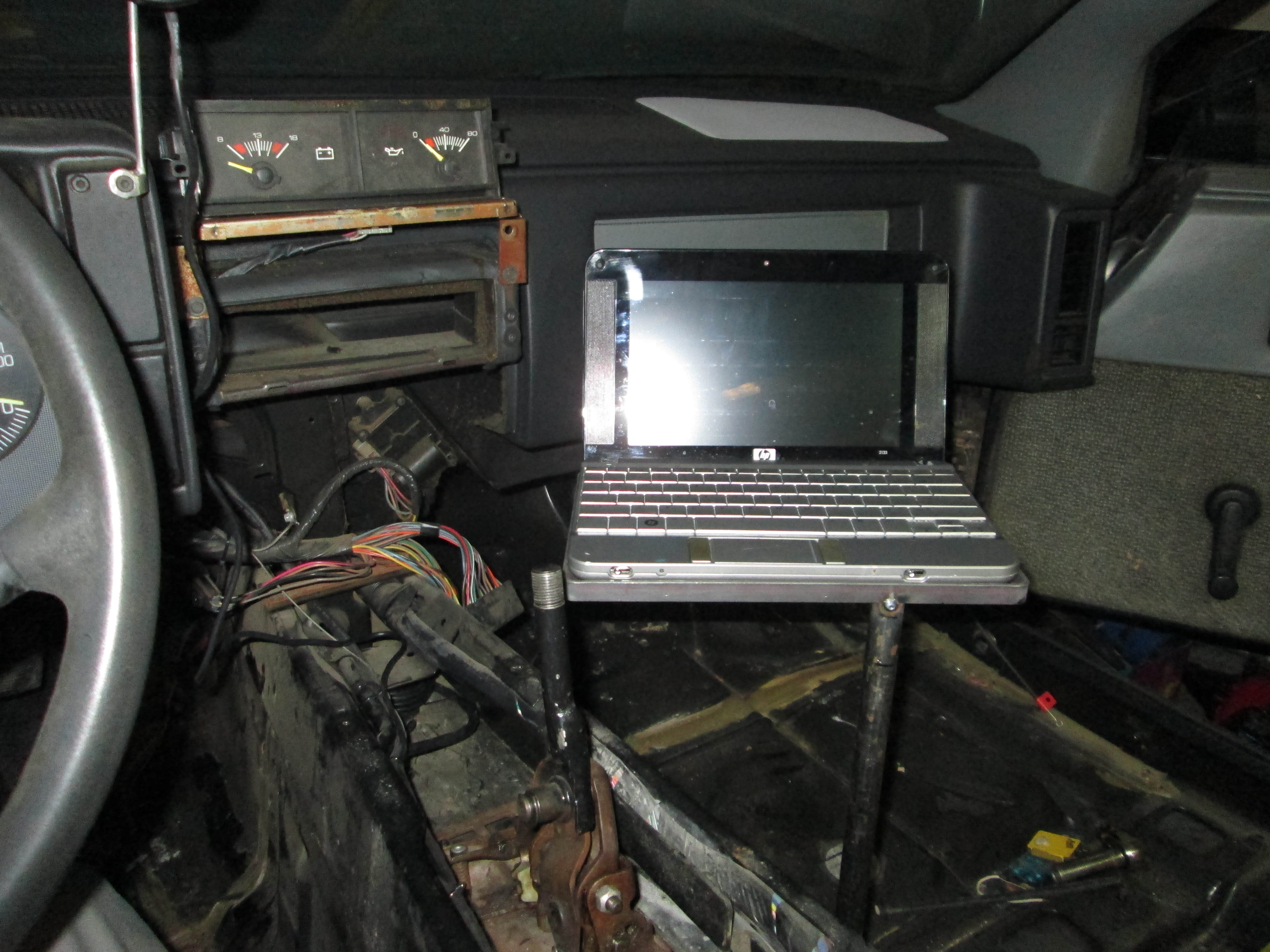
Stop being so contentious for a minute and be serious. How is a laptop gonna sit there while you're making 1-G turns?
Oh, and BTW, in GM's Heritage Center I found more proof that some late '88 'vettes did come with the ZF.
You can PM your apology.
Stop being so contentious for a minute and be serious. How is a laptop gonna sit there while you're making 1-G turns?
Oh, and BTW, in GM's Heritage Center I found more proof that some late '88 'vettes did come with the ZF.
You can PM your apology.
02-21-2013, 06:11 PM
#112
Course you haven't changed either.
Stop being so contentious for a minute and be serious. How is a laptop gonna sit there while you're making 1-G turns?
Oh, and BTW, in GM's Heritage Center I found more proof that some late '88 'vettes did come with the ZF.
You can PM your apology.
Stop being so contentious for a minute and be serious. How is a laptop gonna sit there while you're making 1-G turns?
Oh, and BTW, in GM's Heritage Center I found more proof that some late '88 'vettes did come with the ZF.
You can PM your apology.
The GM Heritage Center also used to house the 1990 Fiero... but that doesn't mean it ever was put into production. I am sure there were some R&D mules of the earlier models that did receive the ZF6, just like there was an 86 Vette with an LT5... but that doesn't mean they were available for purchase through your dealer.
Here is a thread on a corvette forum discussing the exact issue:
http://forums.corvetteforum.com/c4-g...odel-year.html
 02-23-2013, 04:28 PM
#114
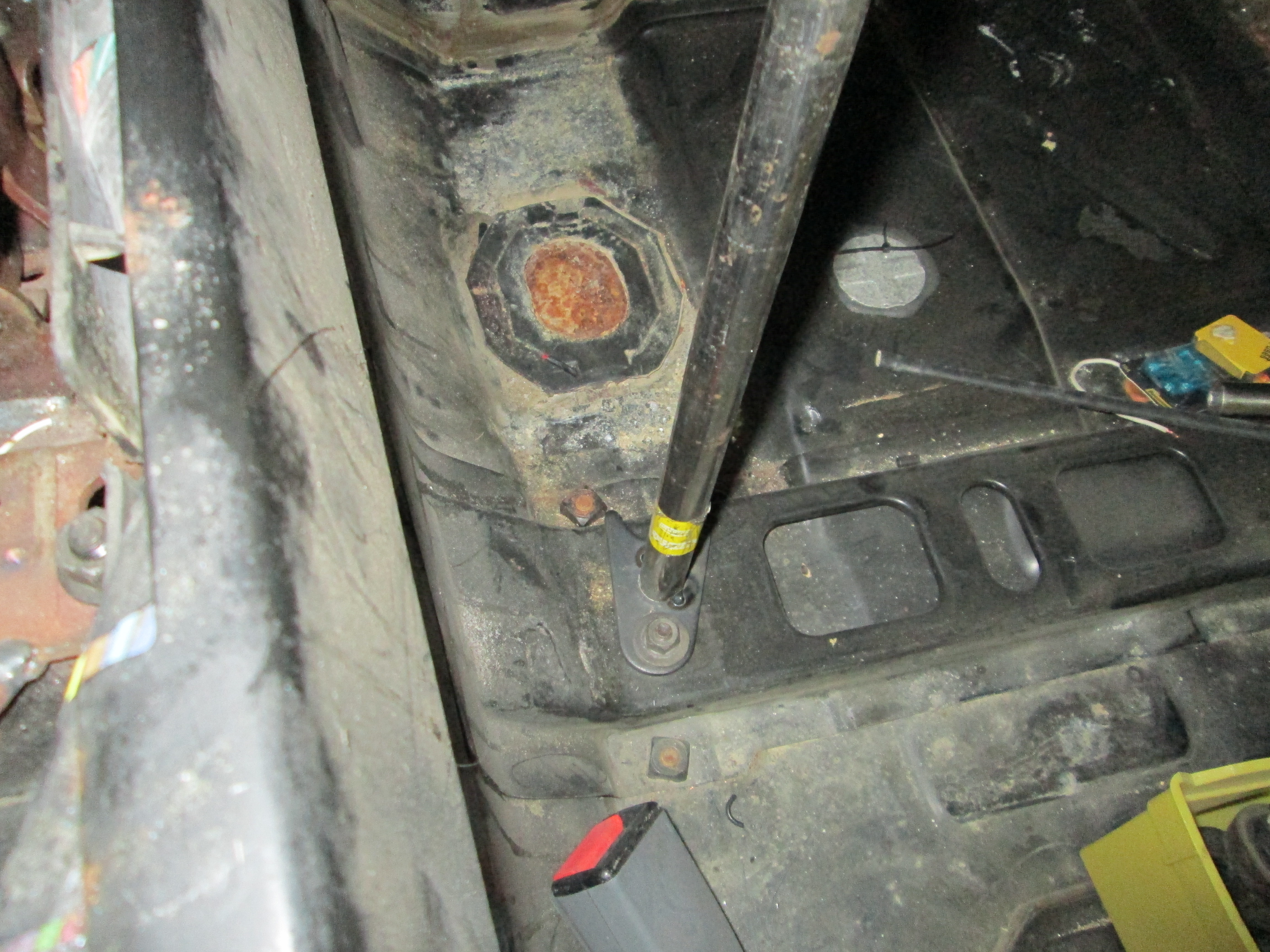
Here is the fully welded laptop stand (the braces are 5/16" brake line):
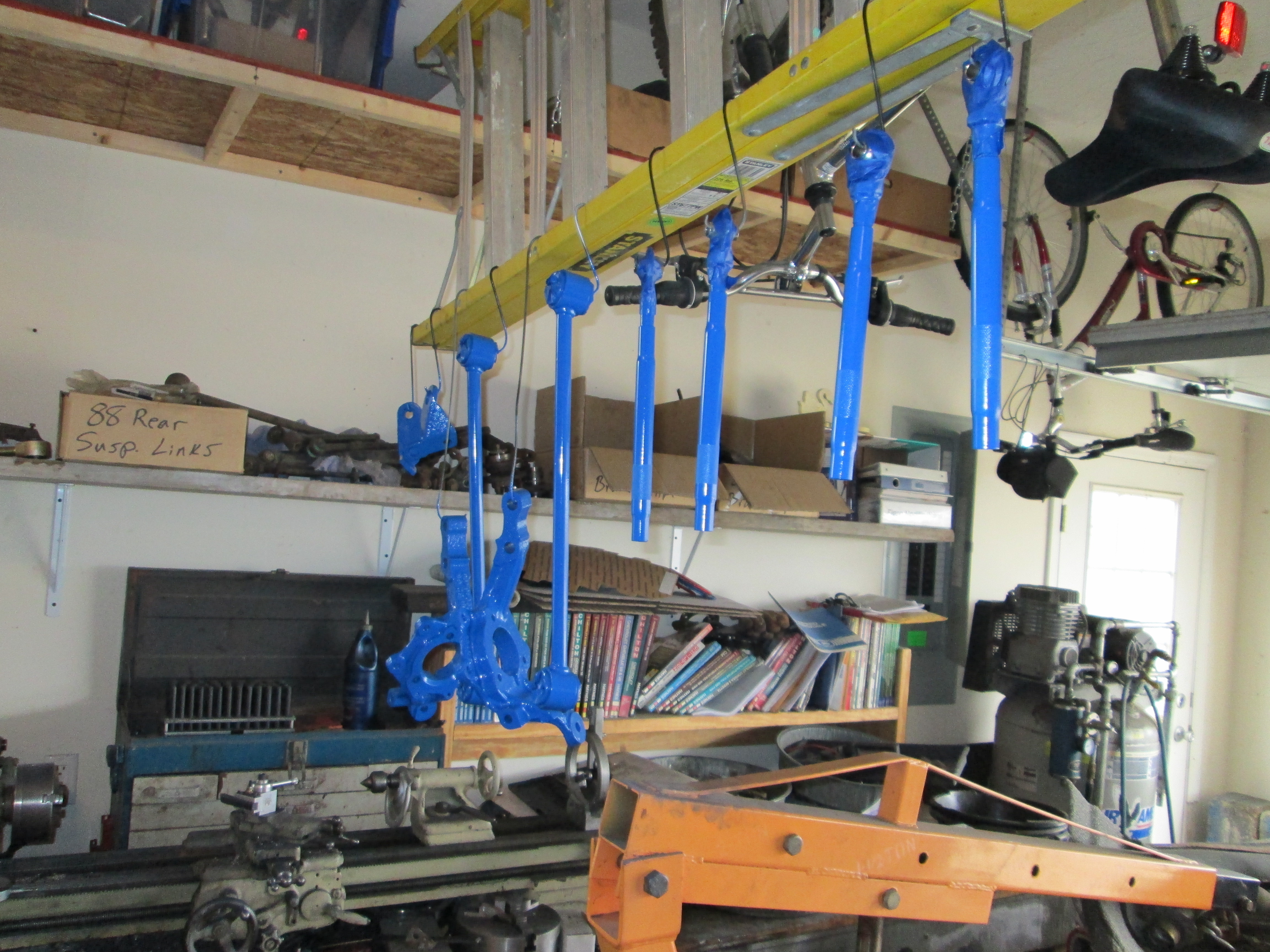
While waiting for the springs I was setting everything up on the table for the rear suspension:
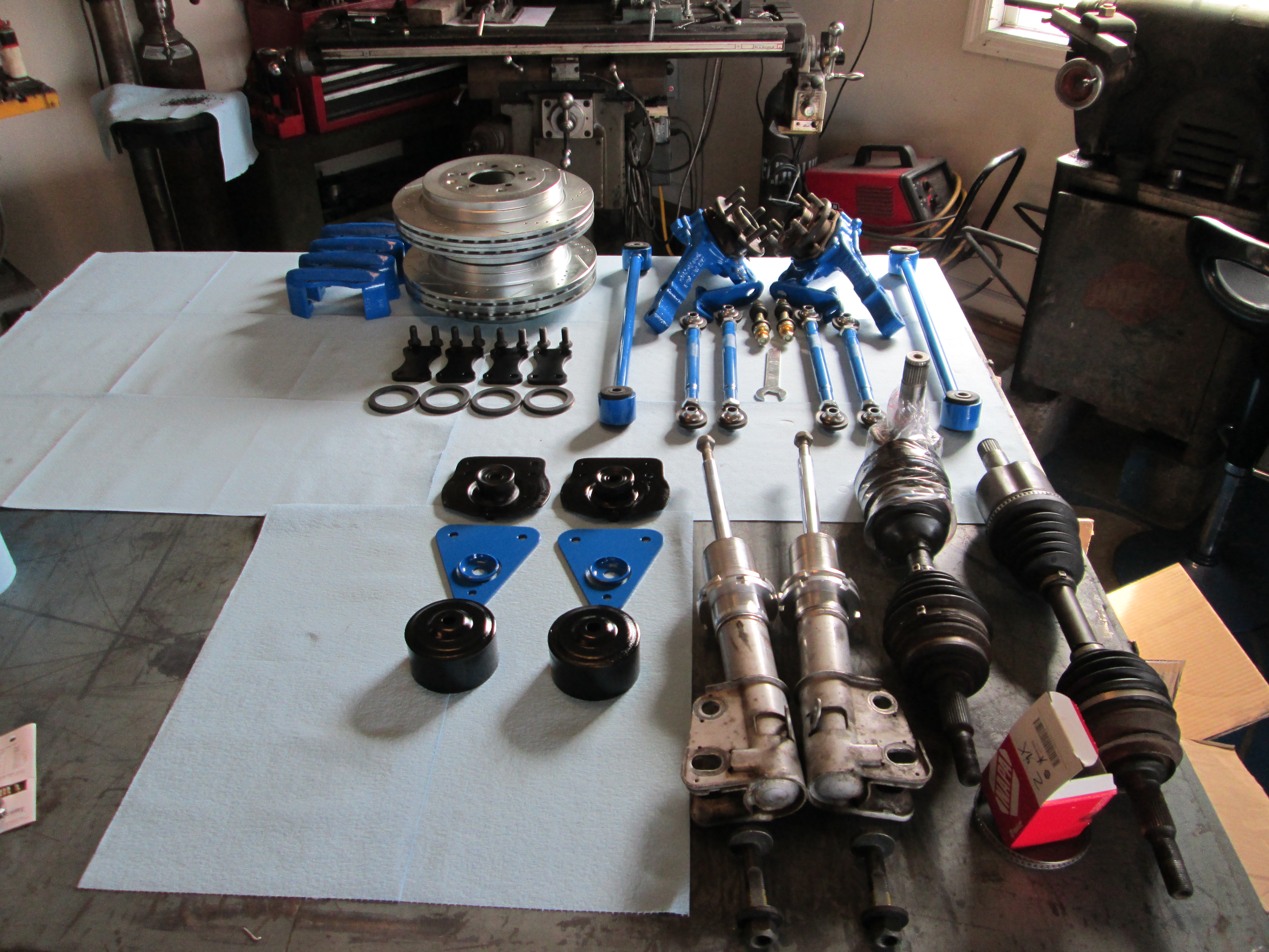
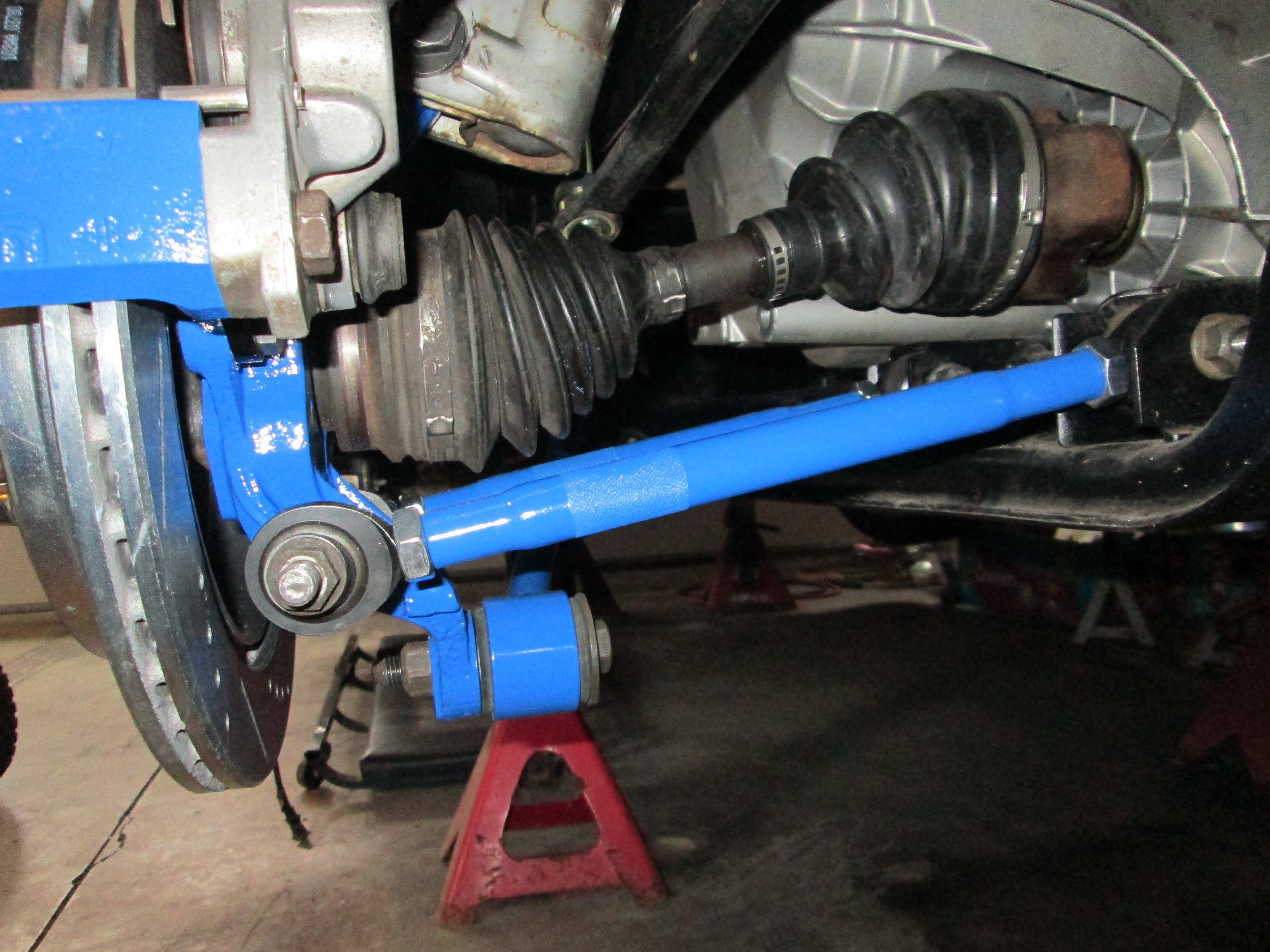
Since the springs are now on backorder and won't be here for a couple weeks, I went ahead and started putting things together using the short/stiff springs that came with the eBay coilover kit... they will work till the right ones show up. The passenger side is mostly assembled except for the brakes. Still waiting on the braided stainless lines to finish this side up.
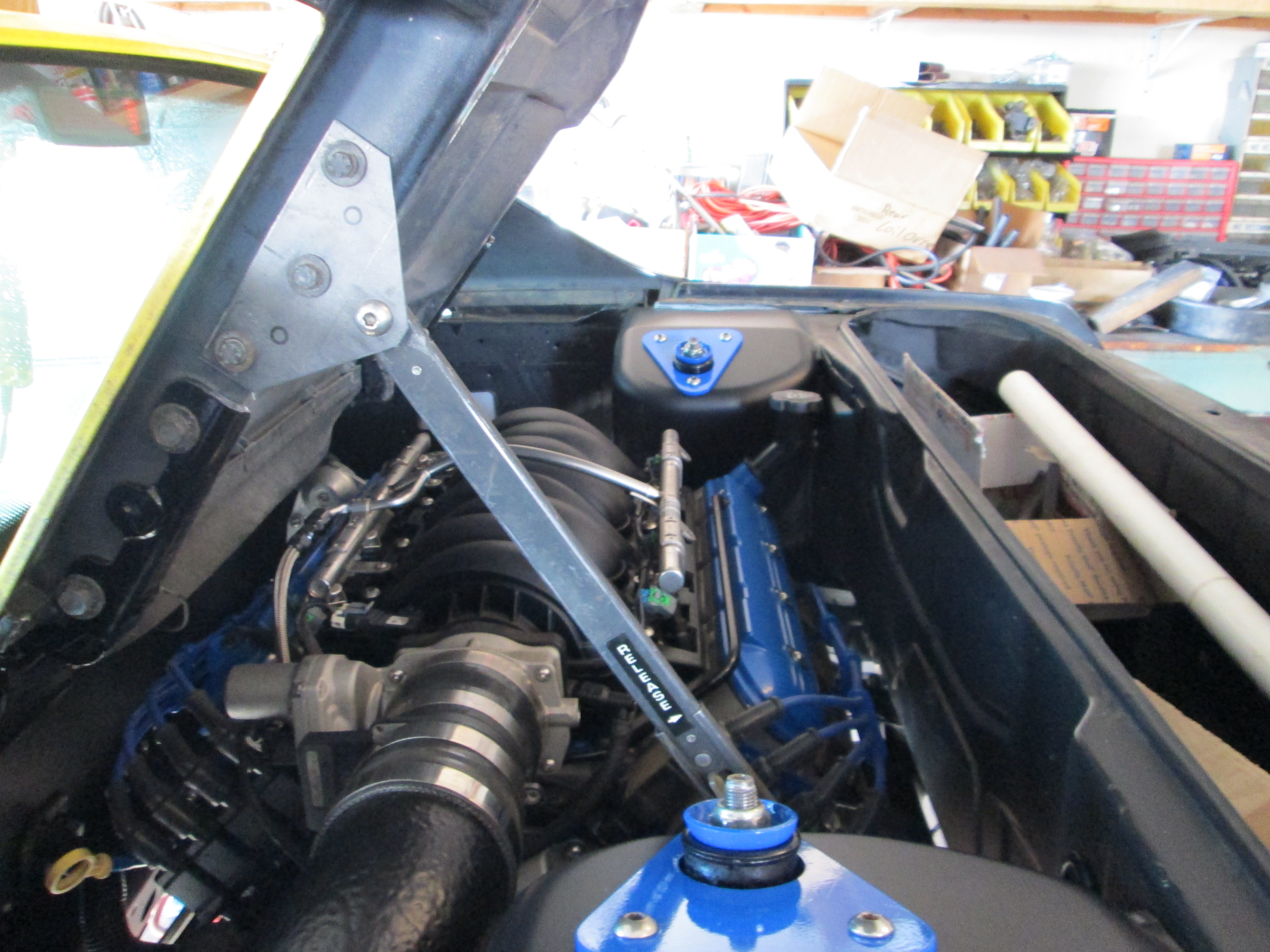
The Driver side I couldn't make much progress as I am waiting for the Corsica CV boot to arrive. Not sure what happened to it, but my guess is it was pitched in the trash during the move... I did install the driver side strut so I could get a good picture of the finished engine bay (excuse the dirty decklid):
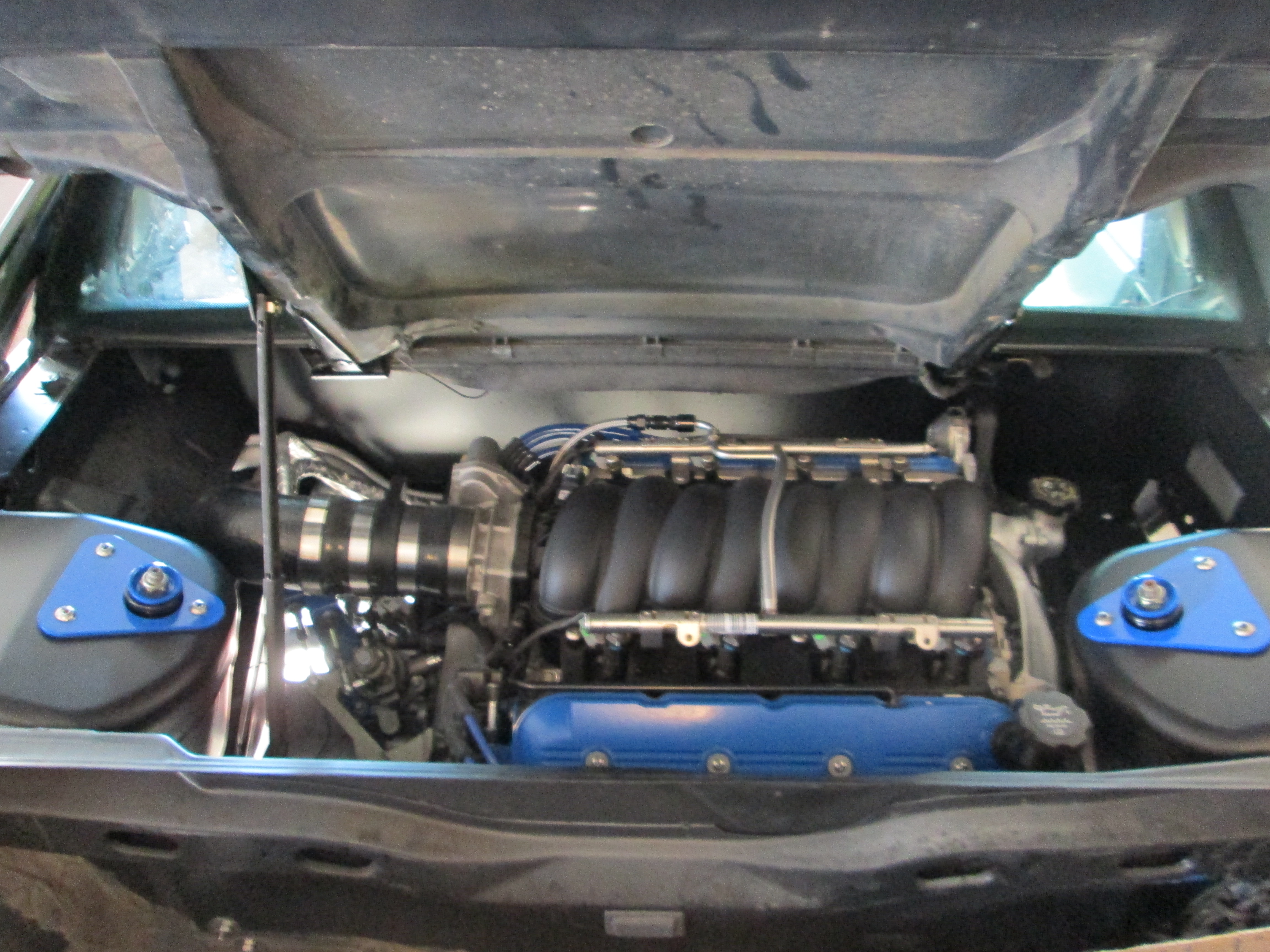
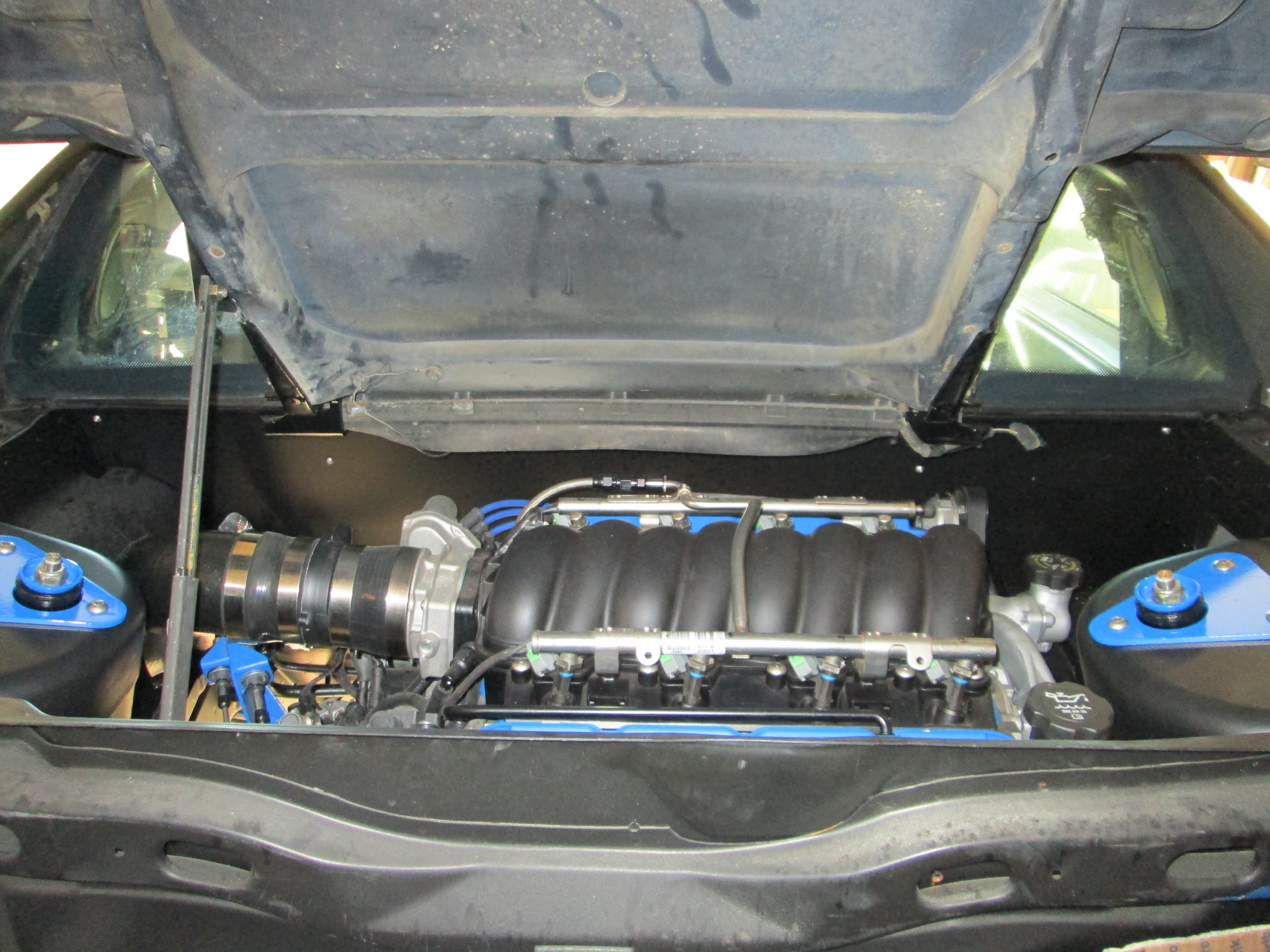
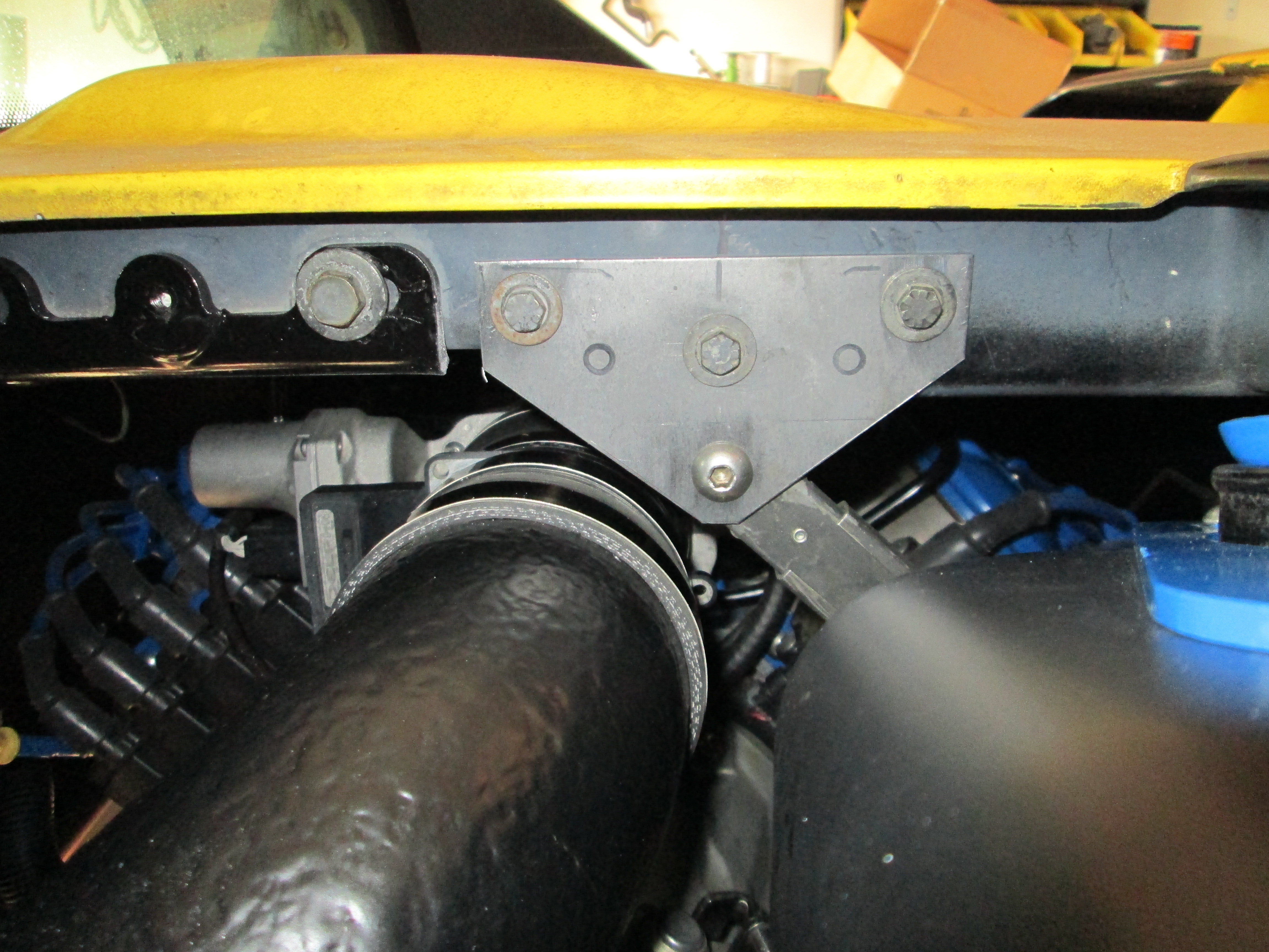
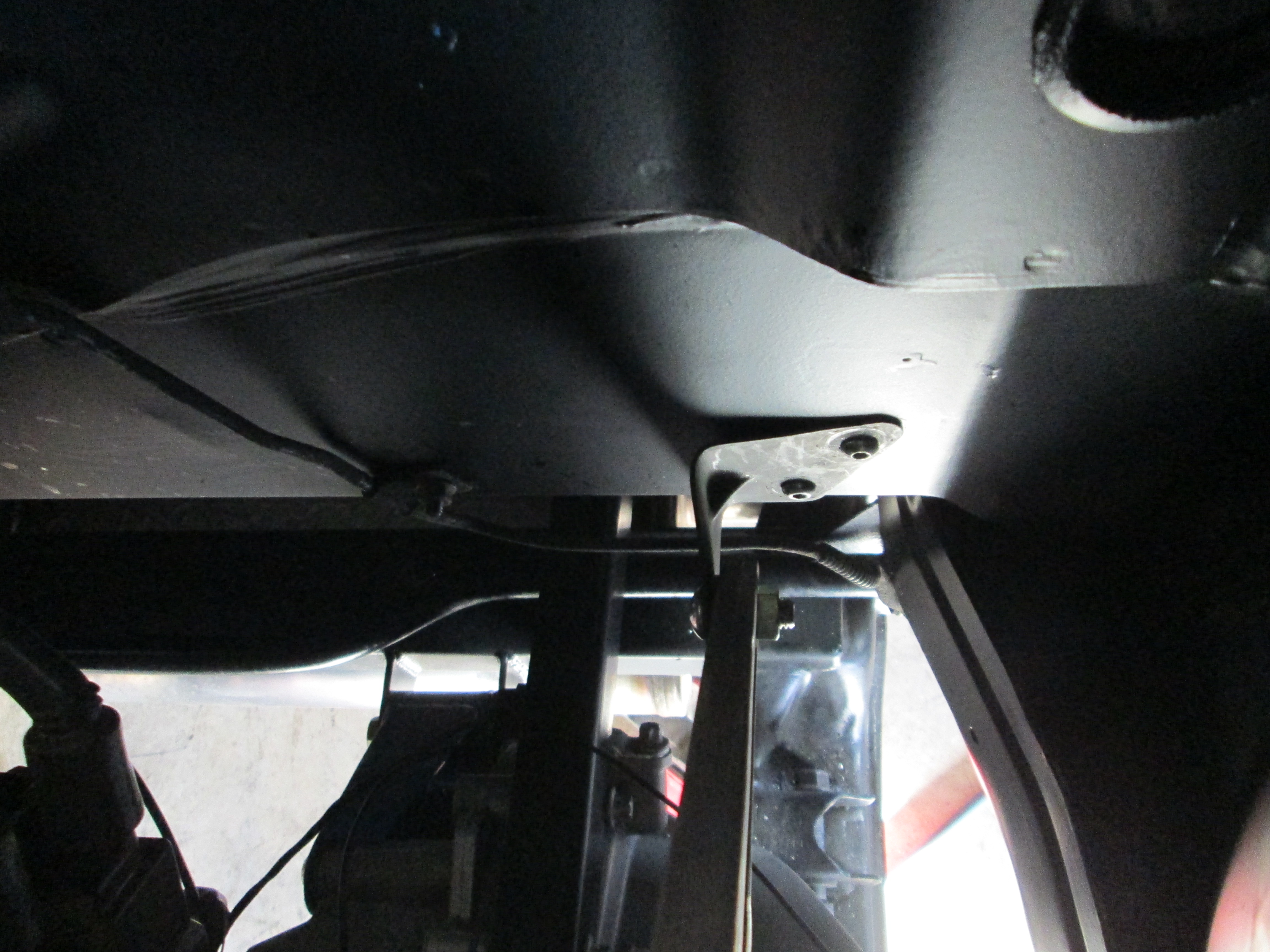
Tops of the struts (relocated inboard 1"):
Clearance of the top of the strut with the flipped bushing plate to the decklid:
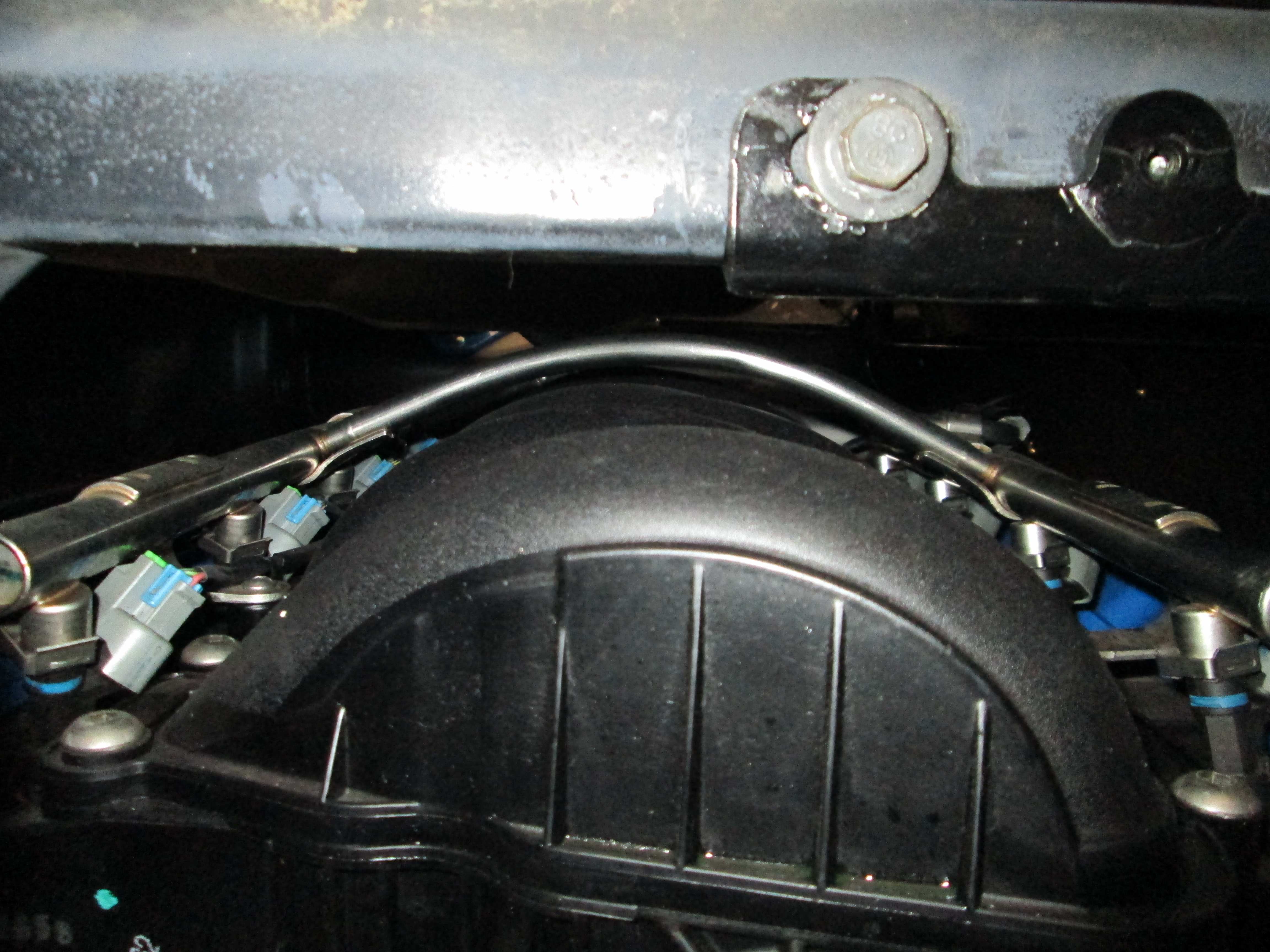
Clearance between top of engine and bottom of decklid (no decklid notching needed on either side):
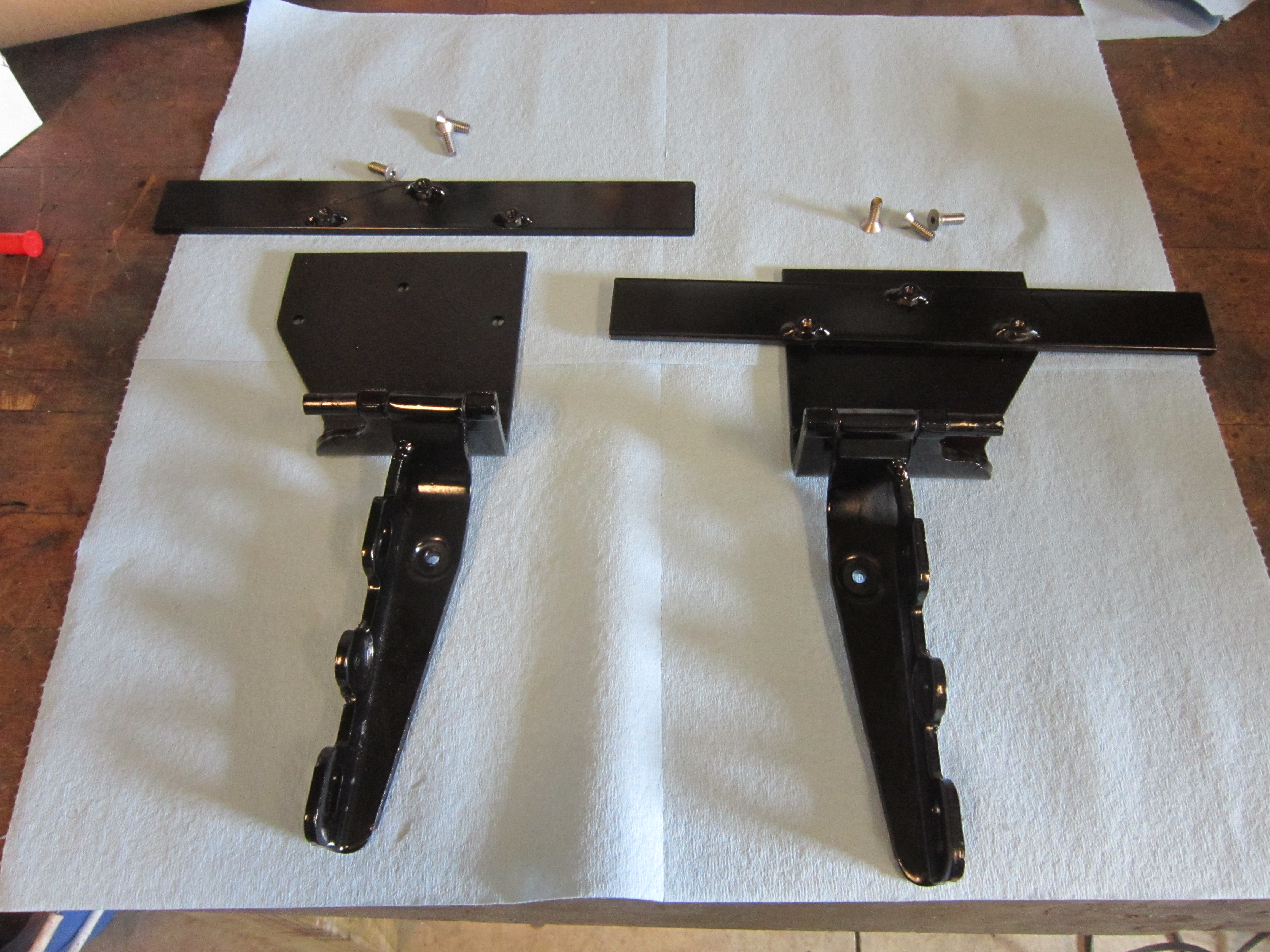
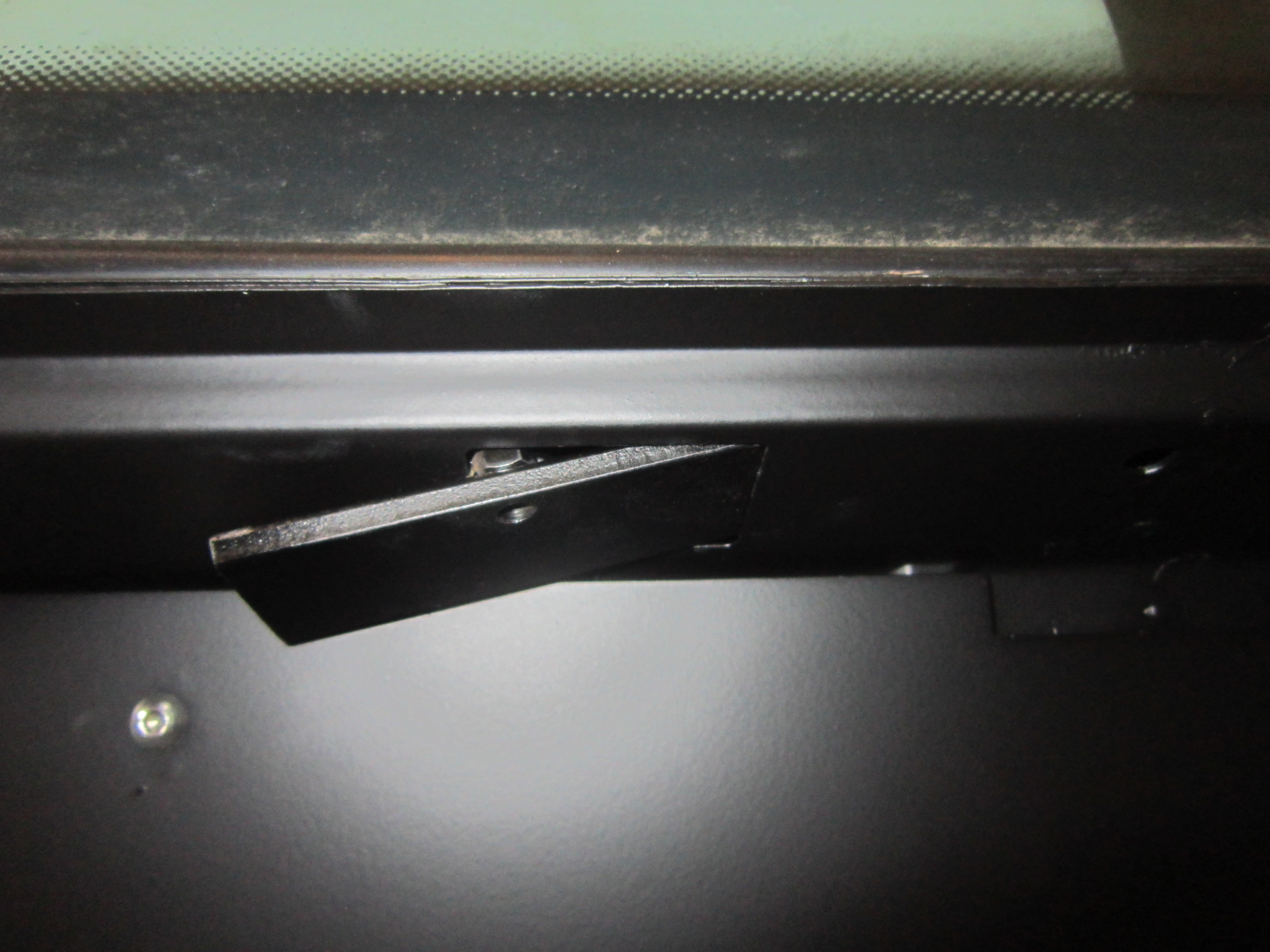
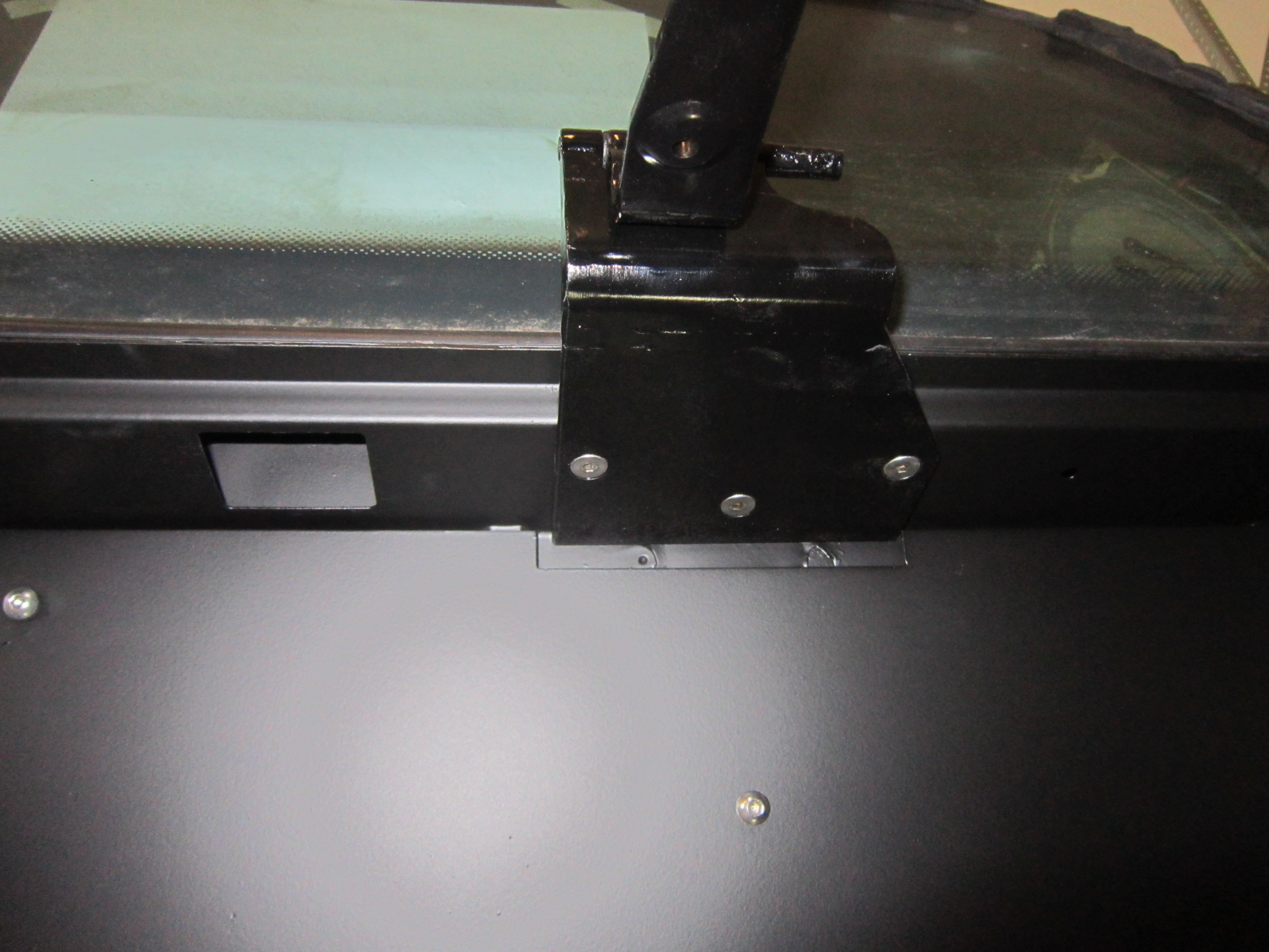
Here is a neat little mod... I shortened the hood support by 3" at the base, used the top bracket for the base, then fabbed up a new upper bracket for use in the rear:
Decklid closed:
Base mounted to the trunk wall:
While waiting for the springs I was setting everything up on the table for the rear suspension:
Since the springs are now on backorder and won't be here for a couple weeks, I went ahead and started putting things together using the short/stiff springs that came with the eBay coilover kit... they will work till the right ones show up. The passenger side is mostly assembled except for the brakes. Still waiting on the braided stainless lines to finish this side up.
The Driver side I couldn't make much progress as I am waiting for the Corsica CV boot to arrive. Not sure what happened to it, but my guess is it was pitched in the trash during the move... I did install the driver side strut so I could get a good picture of the finished engine bay (excuse the dirty decklid):
Tops of the struts (relocated inboard 1"):
Clearance of the top of the strut with the flipped bushing plate to the decklid:
Clearance between top of engine and bottom of decklid (no decklid notching needed on either side):
Here is a neat little mod... I shortened the hood support by 3" at the base, used the top bracket for the base, then fabbed up a new upper bracket for use in the rear:
Decklid closed:
Base mounted to the trunk wall:
03-02-2013, 07:43 PM
#116
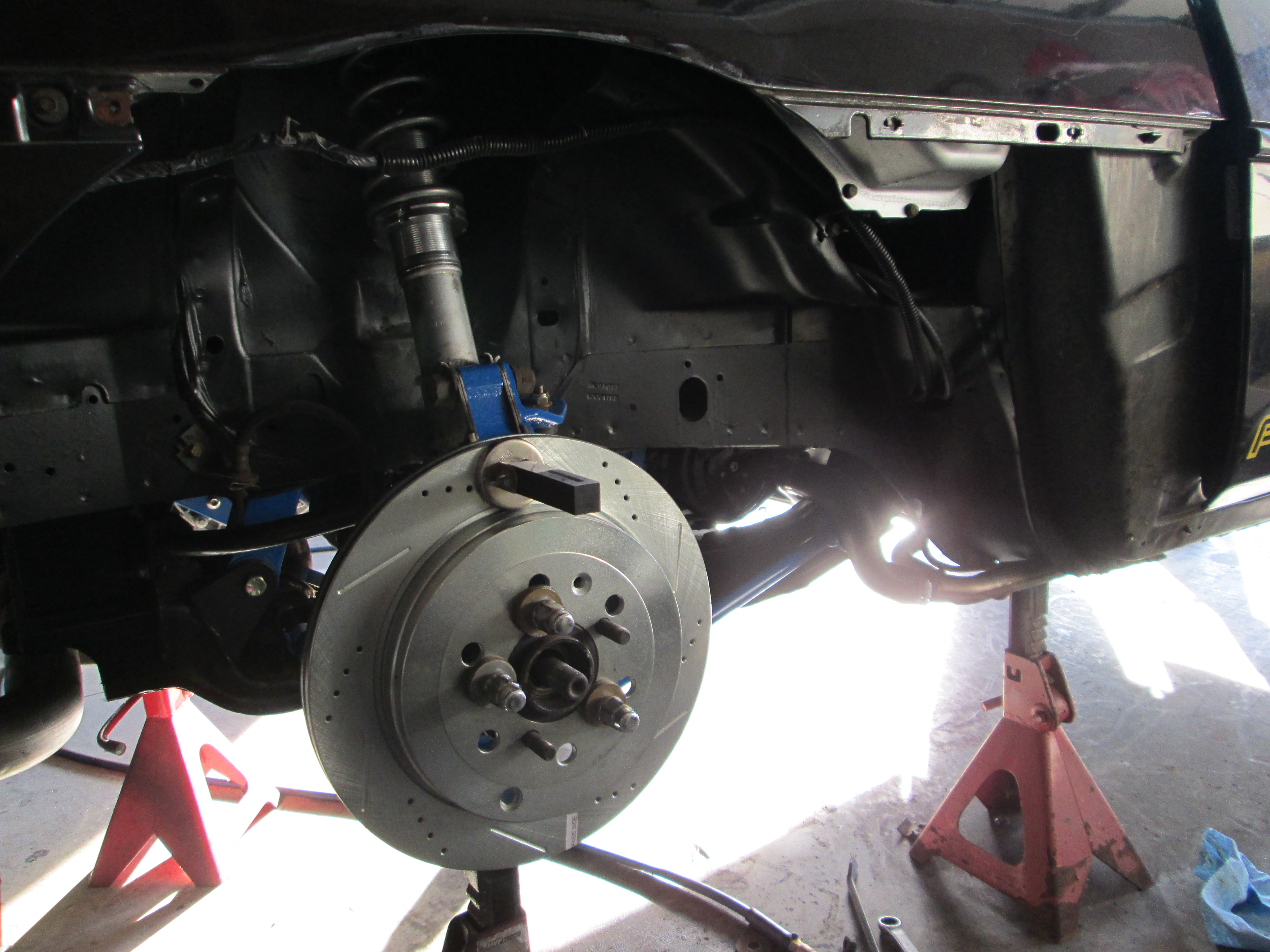
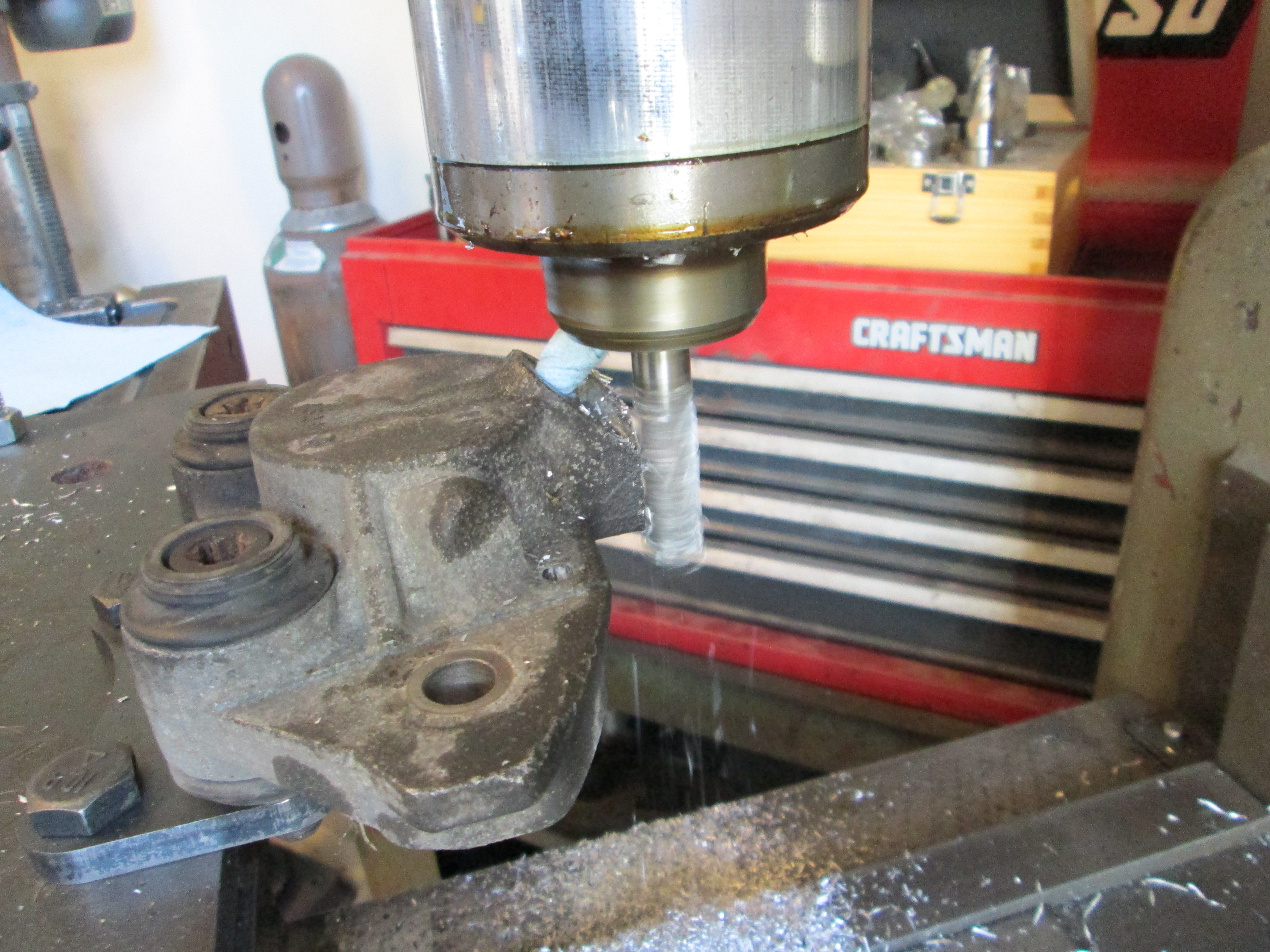
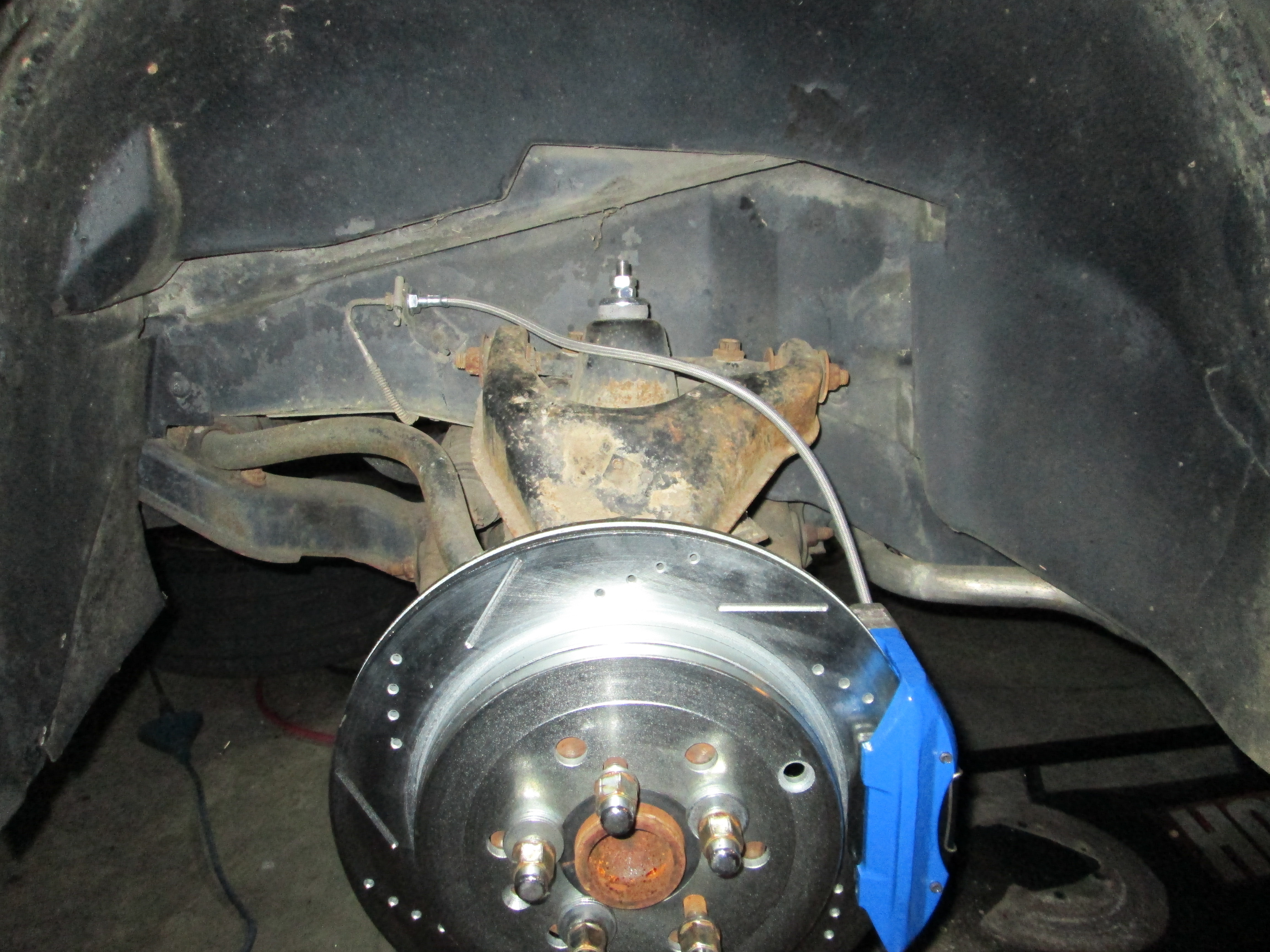
So I can drive this car without having to purchase the rest of the wheels and 4 new tires, I modified the 4 brake calipers to allow use of my 13" brake kit under the 16x7 wheels I currently have. The square boss on top needs to be milled down 1/8" so it will clear the inside of the wheel:
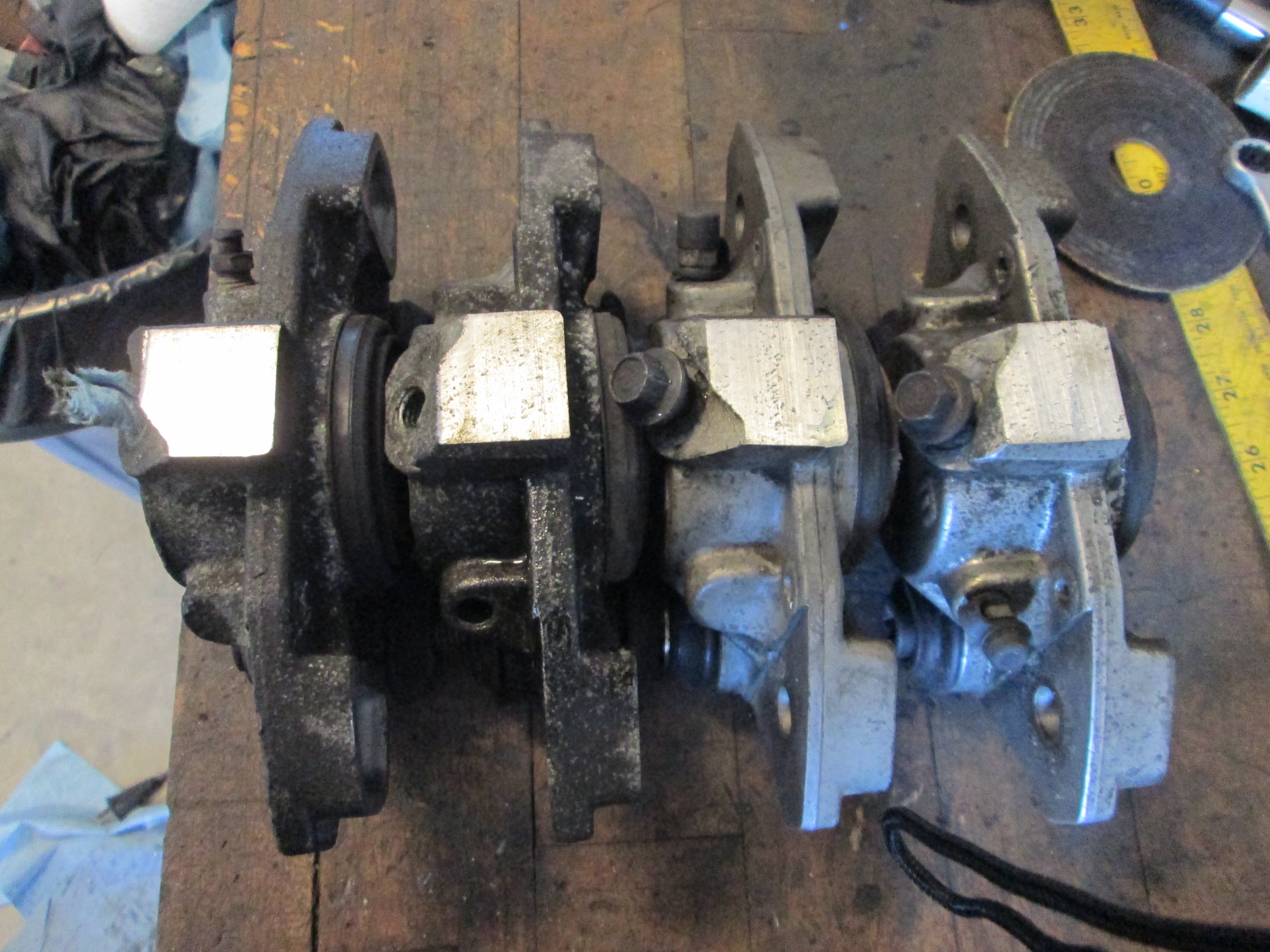
Then I removed the sliders and cleaned/lubed them up and reassembled.
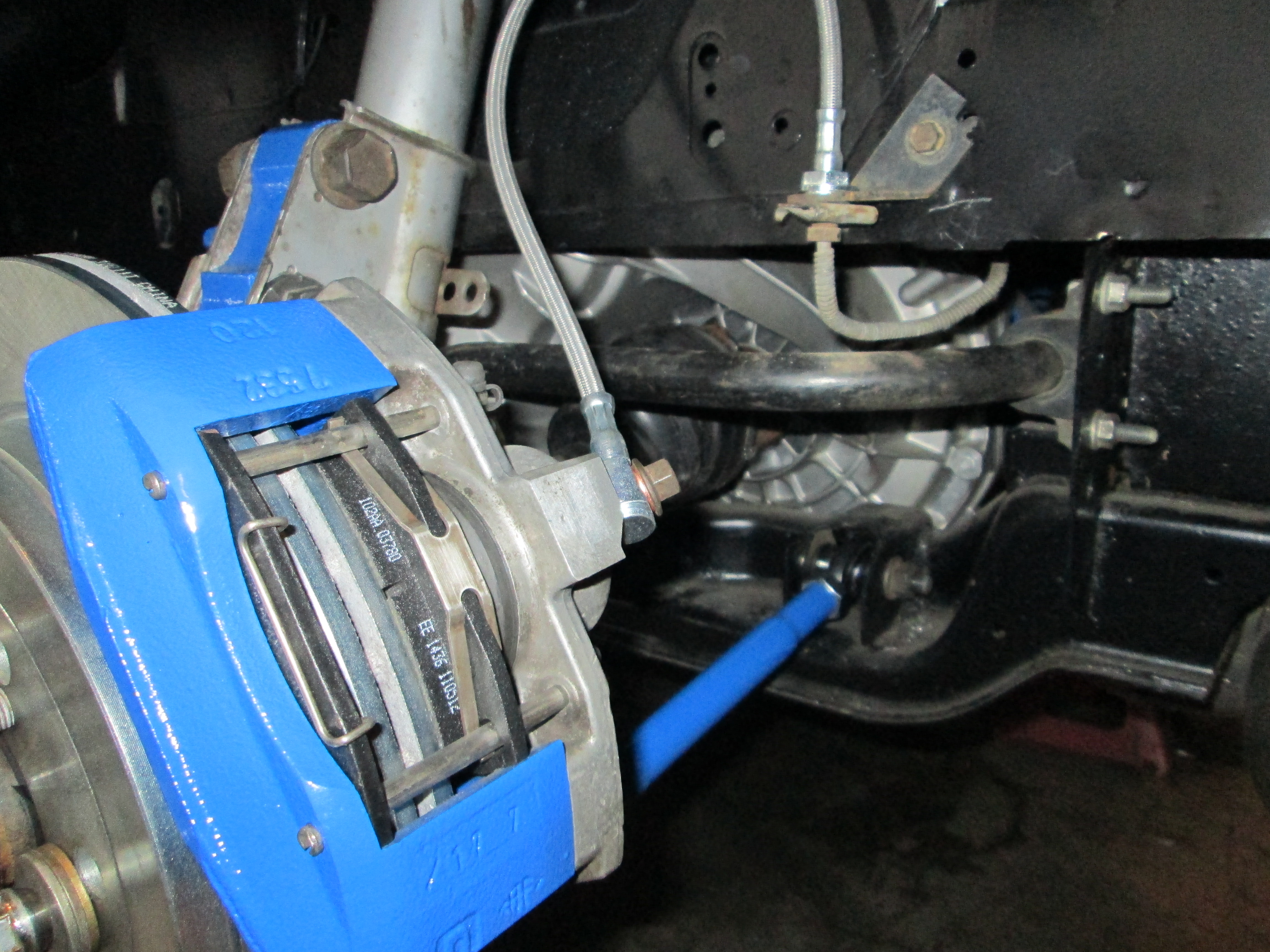
Caliper adapter bracket installed:
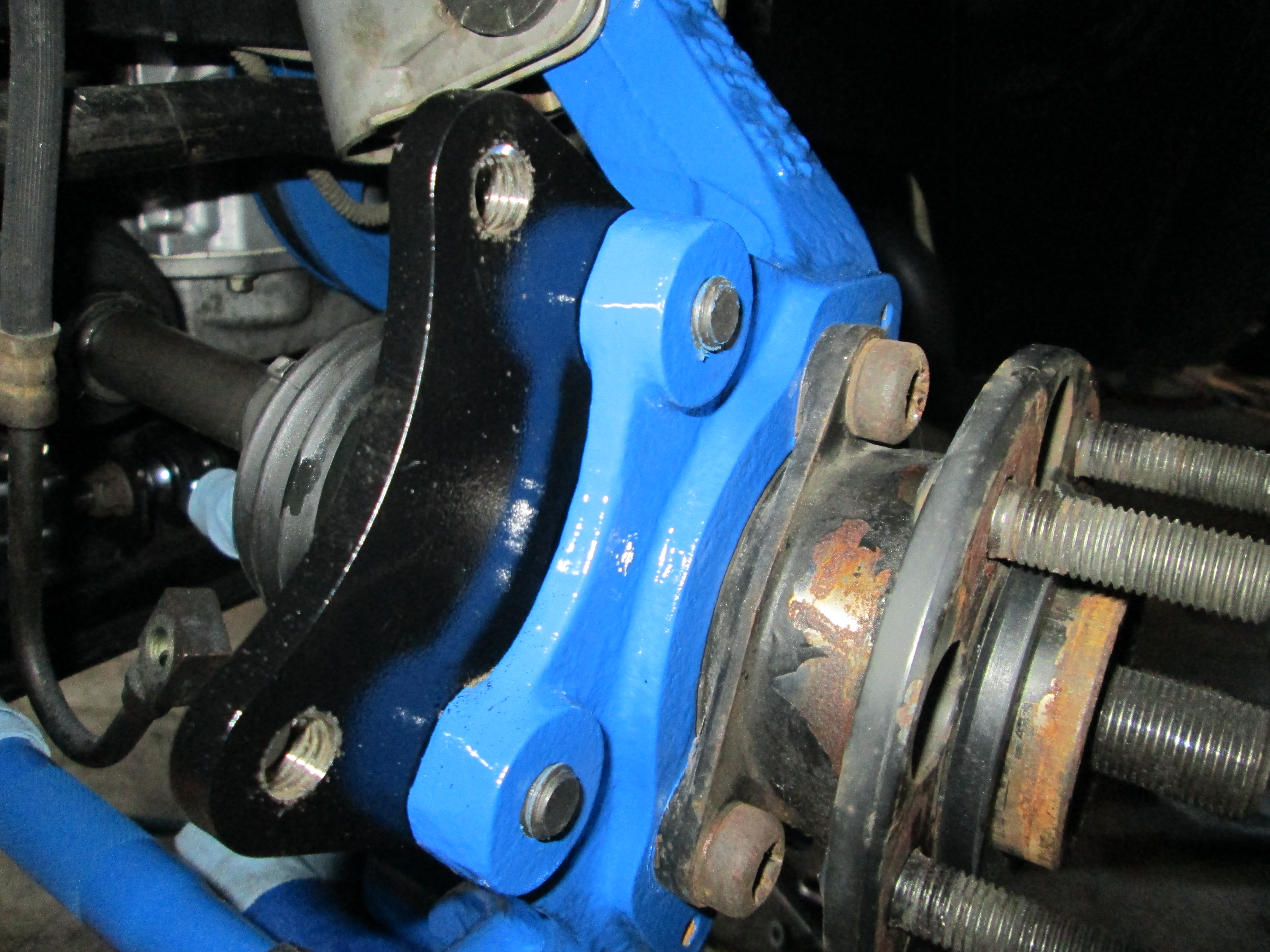
Rotor, caliper and pads installed:
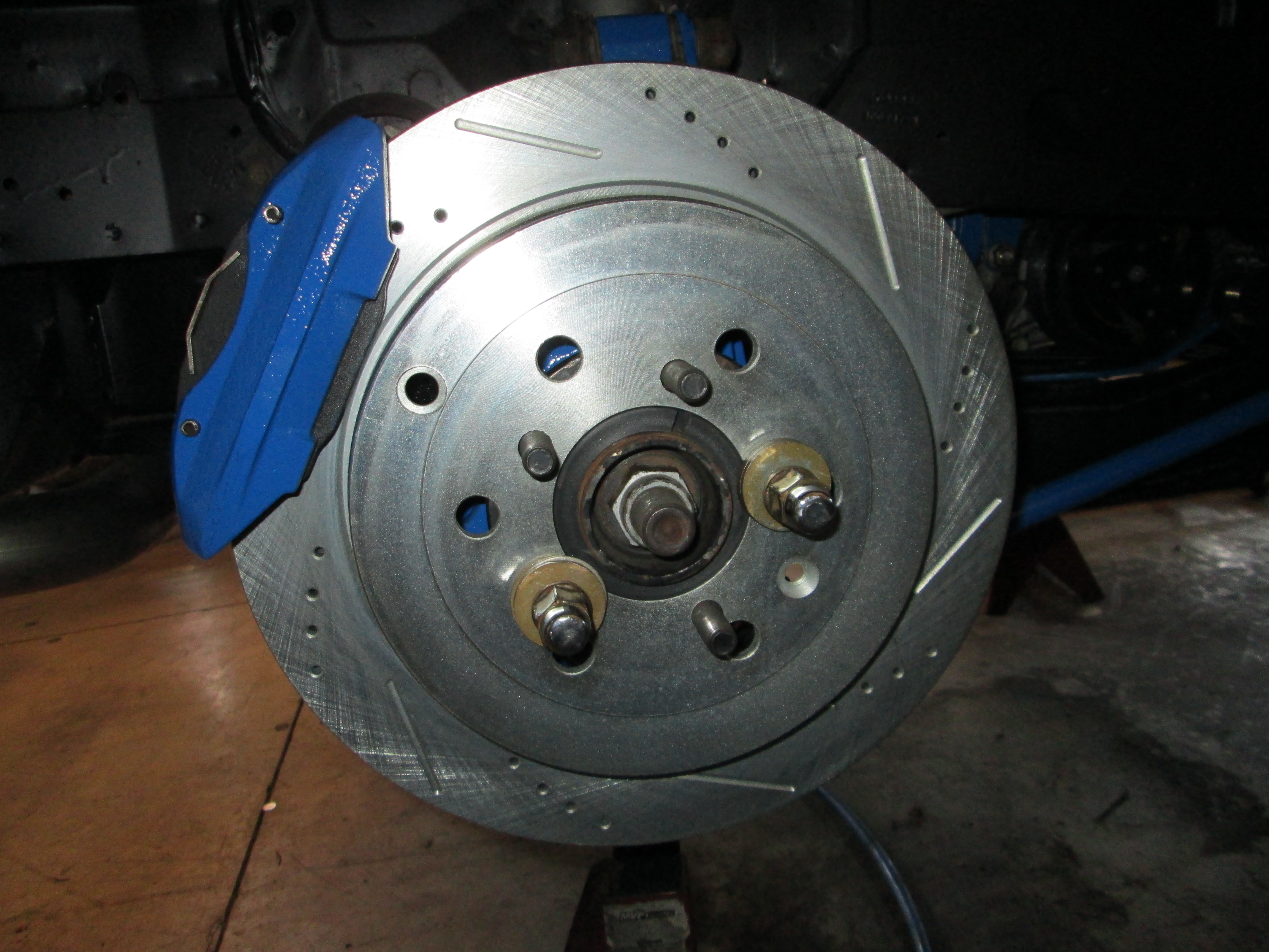
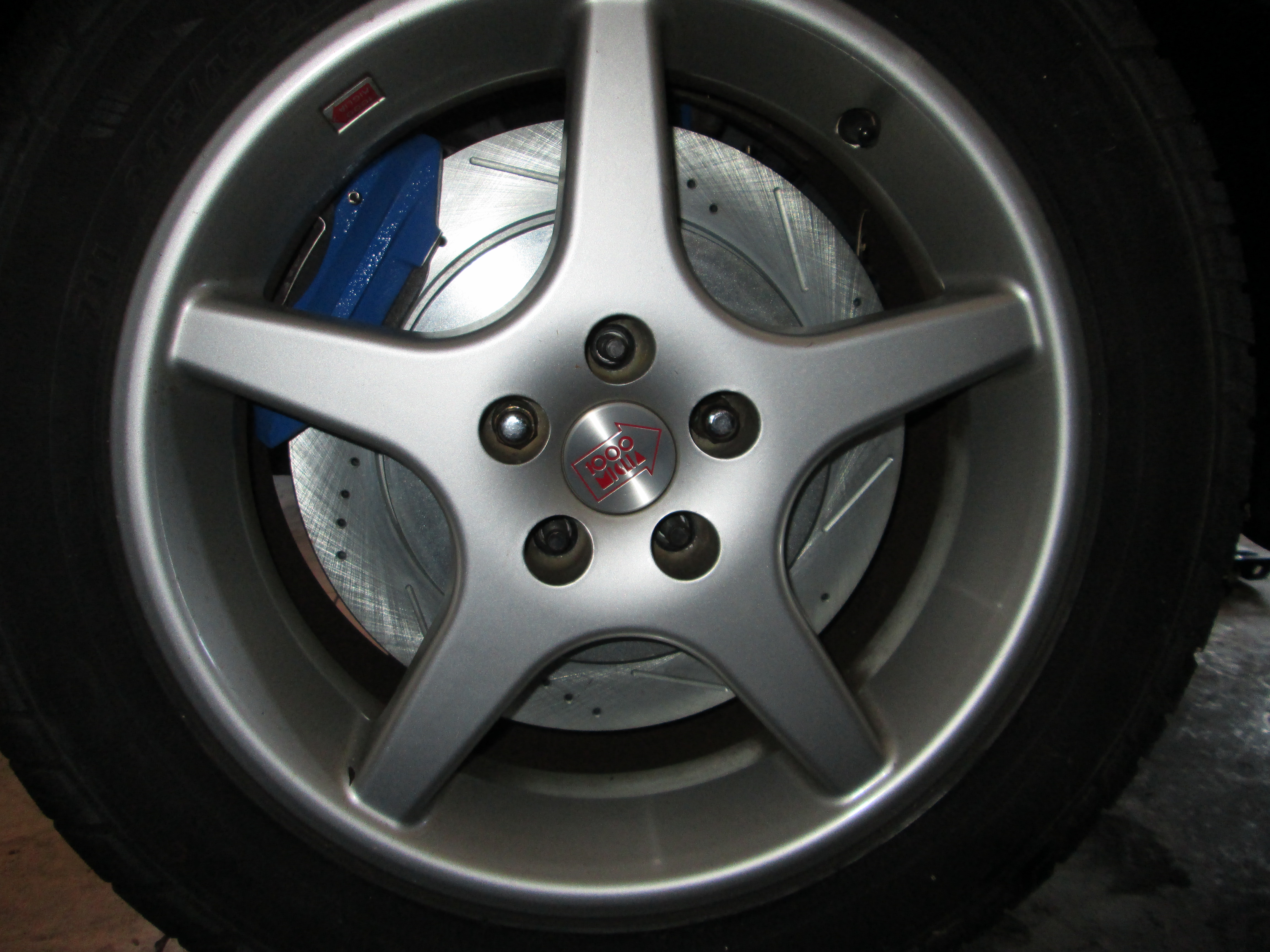
Tucked behind the 16x7 wheel... very, very tight!
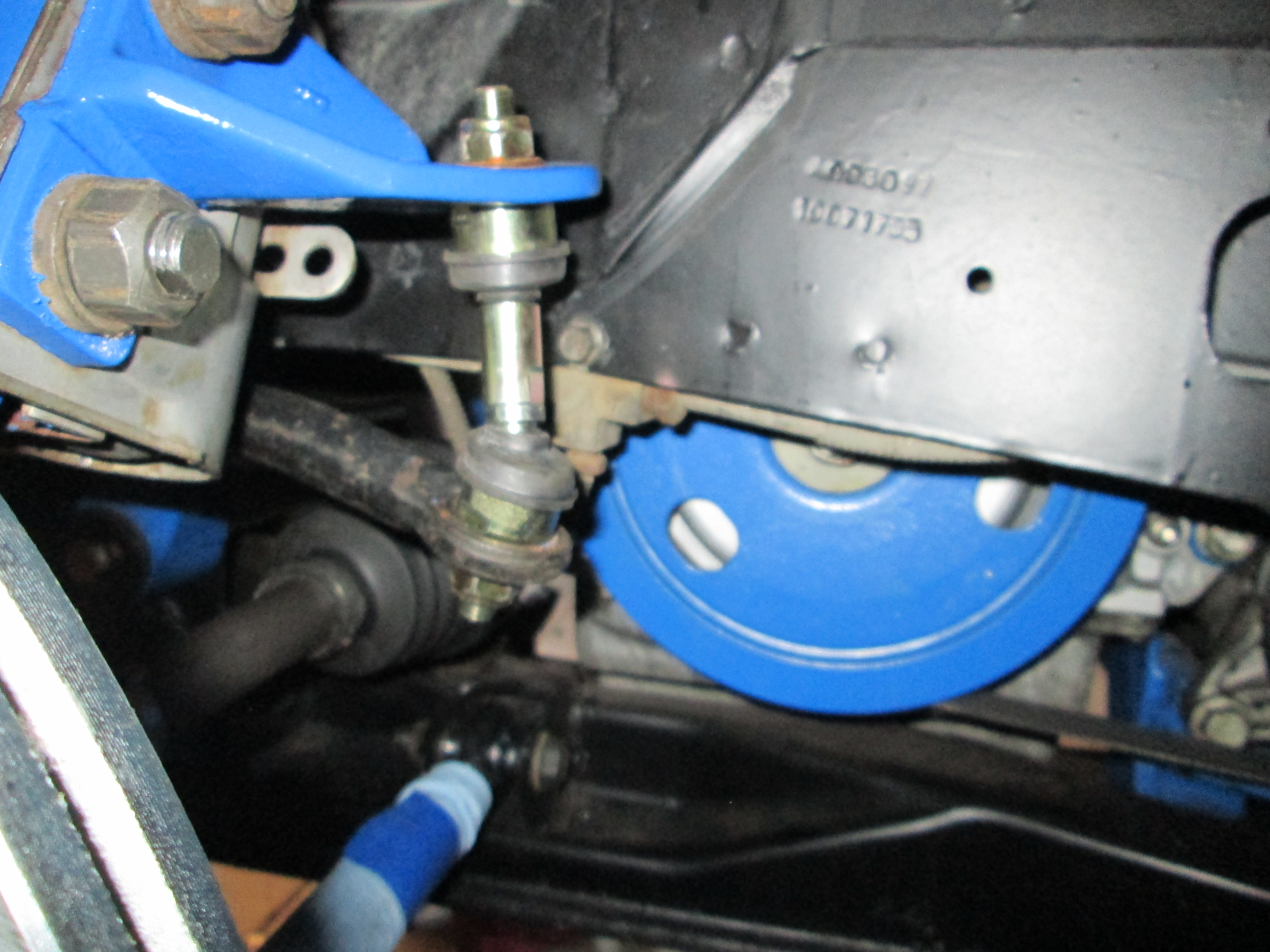
Here is a picture of Rodney's zero lash sway bar links:
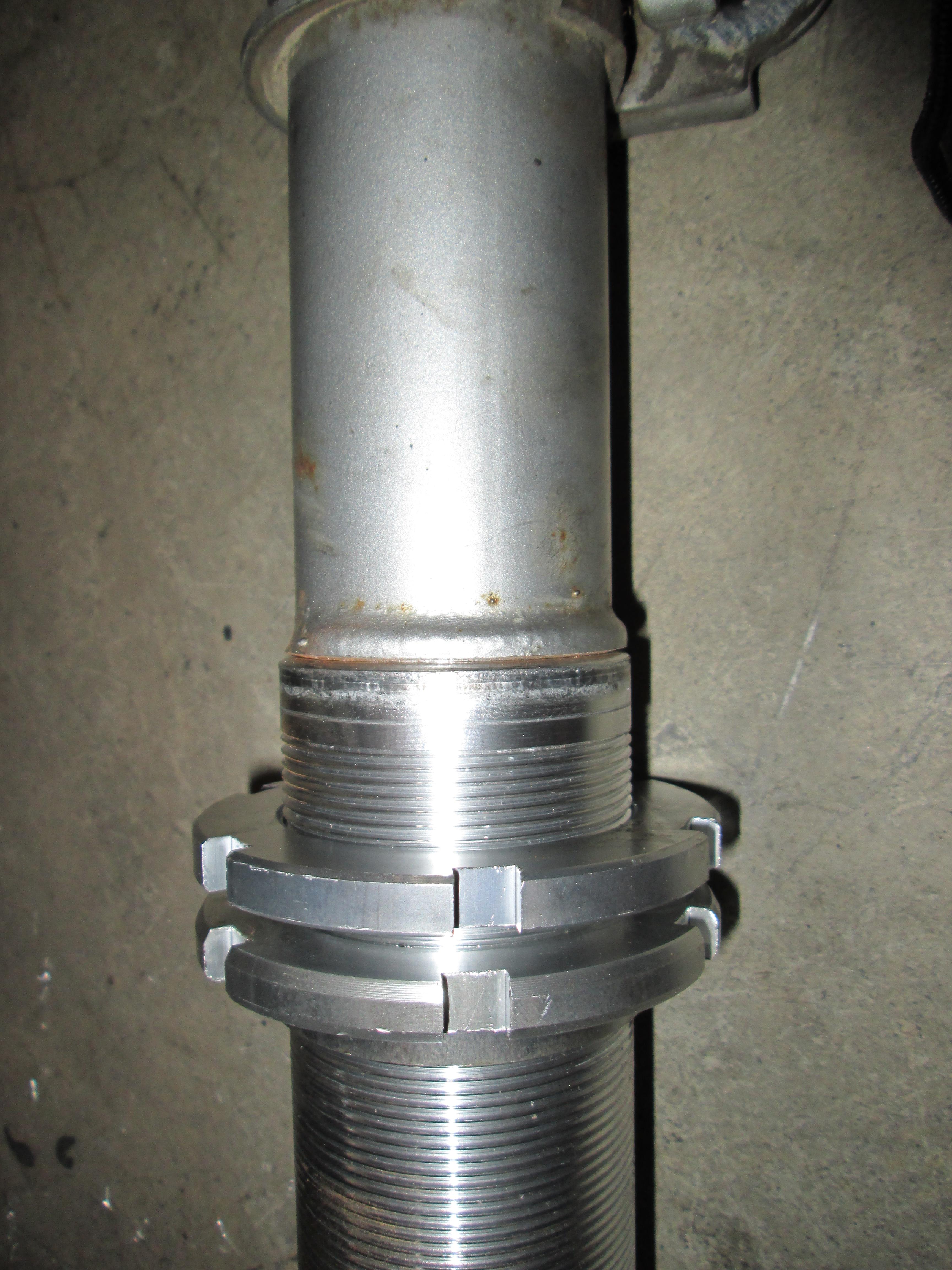
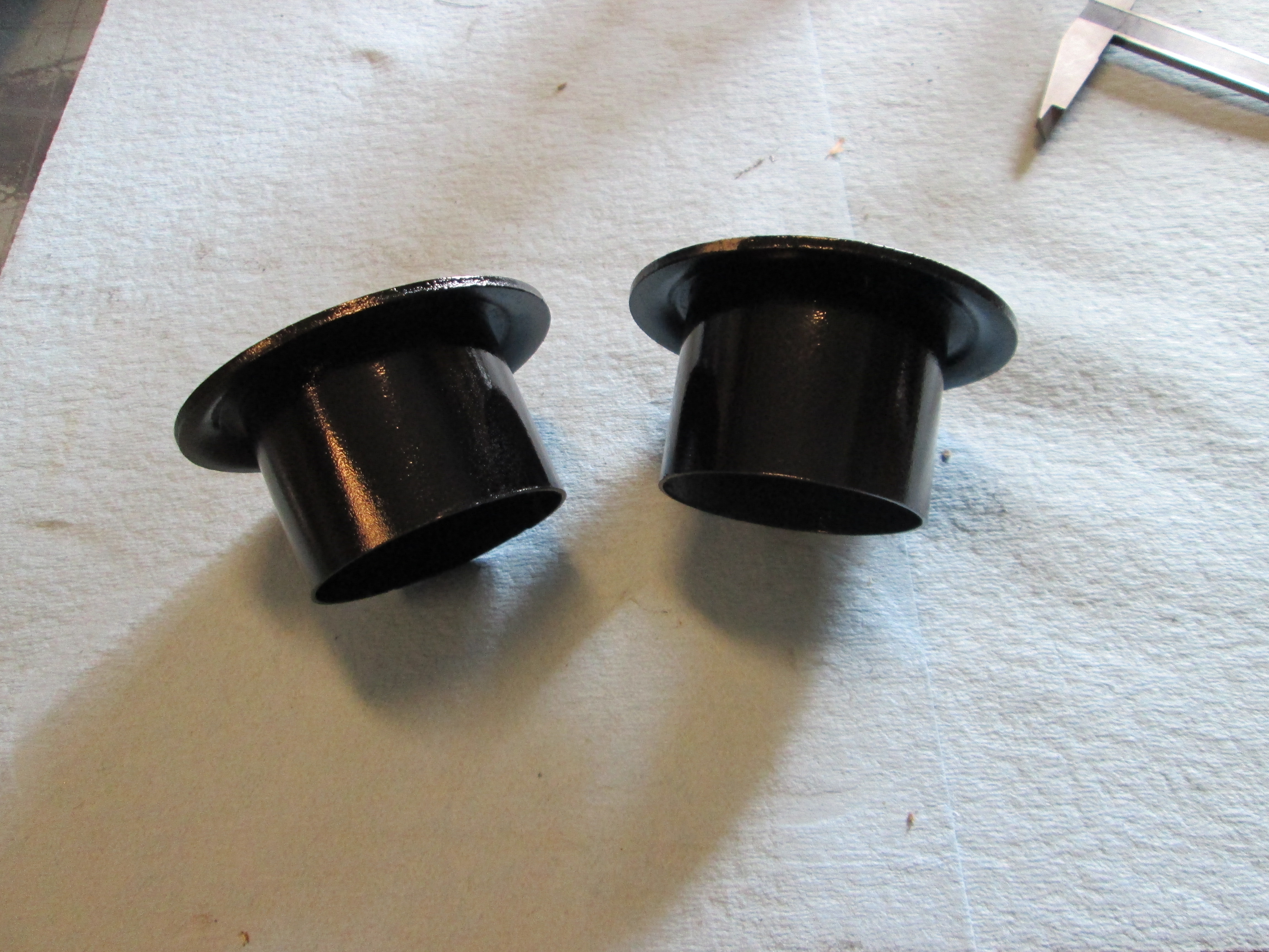
I had to rework the upper spring perch for the new springs (wouldn't fit inside the 3 1/2" tube, so I have to make the sleeve internal):
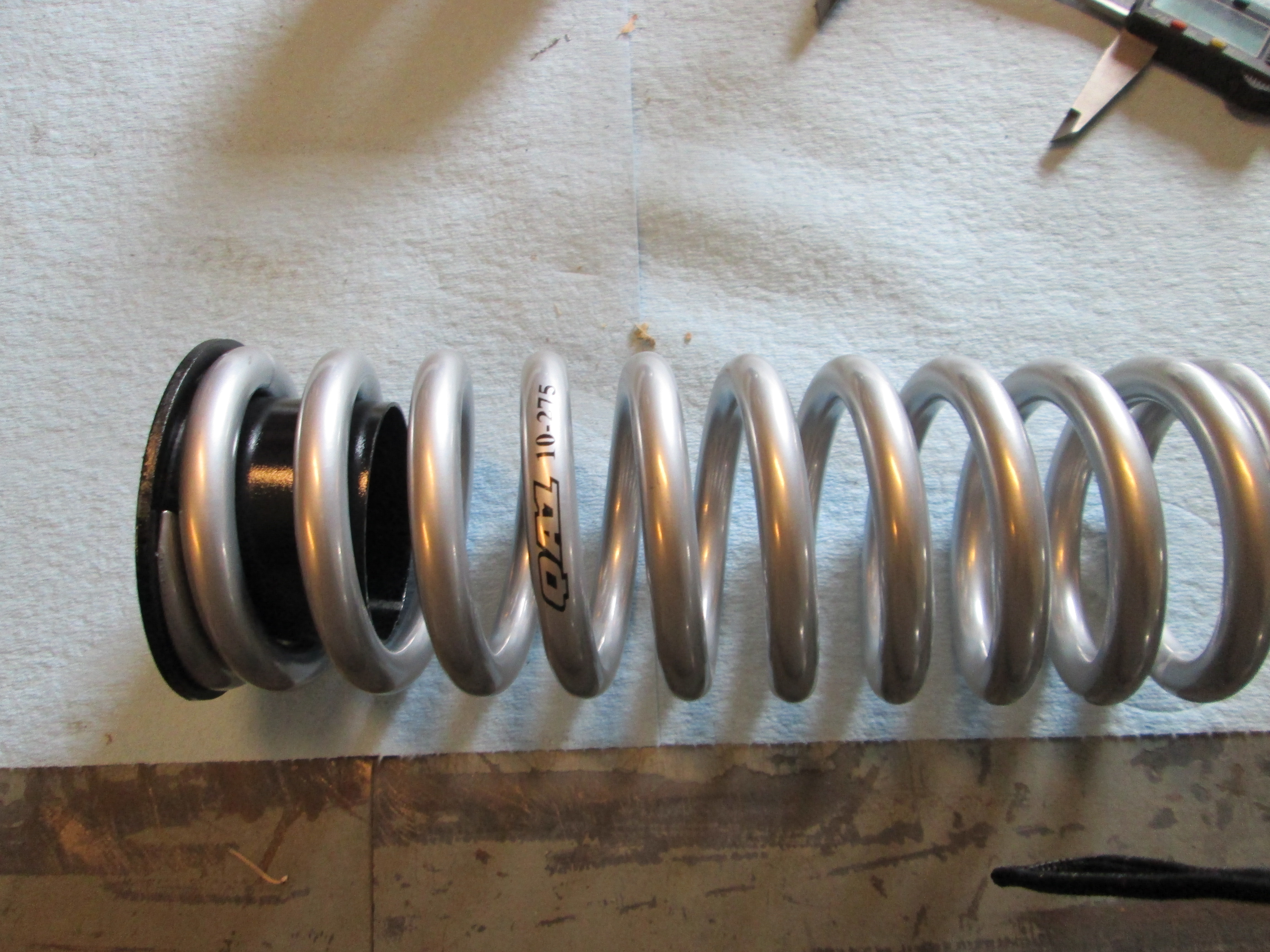
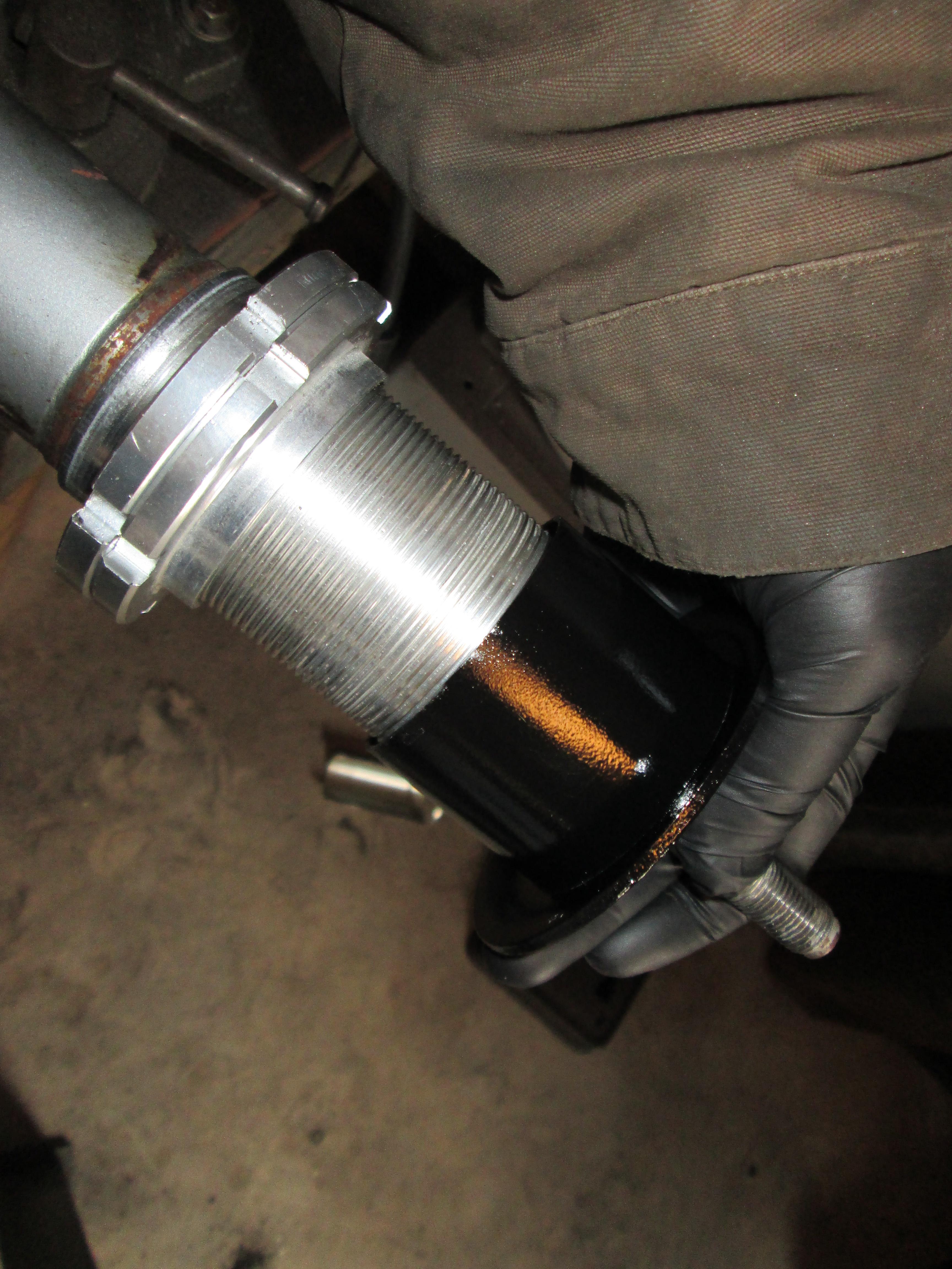
Here I compressed the strut to ensure the inner sleeve would clear the coil over sleeve and it does:
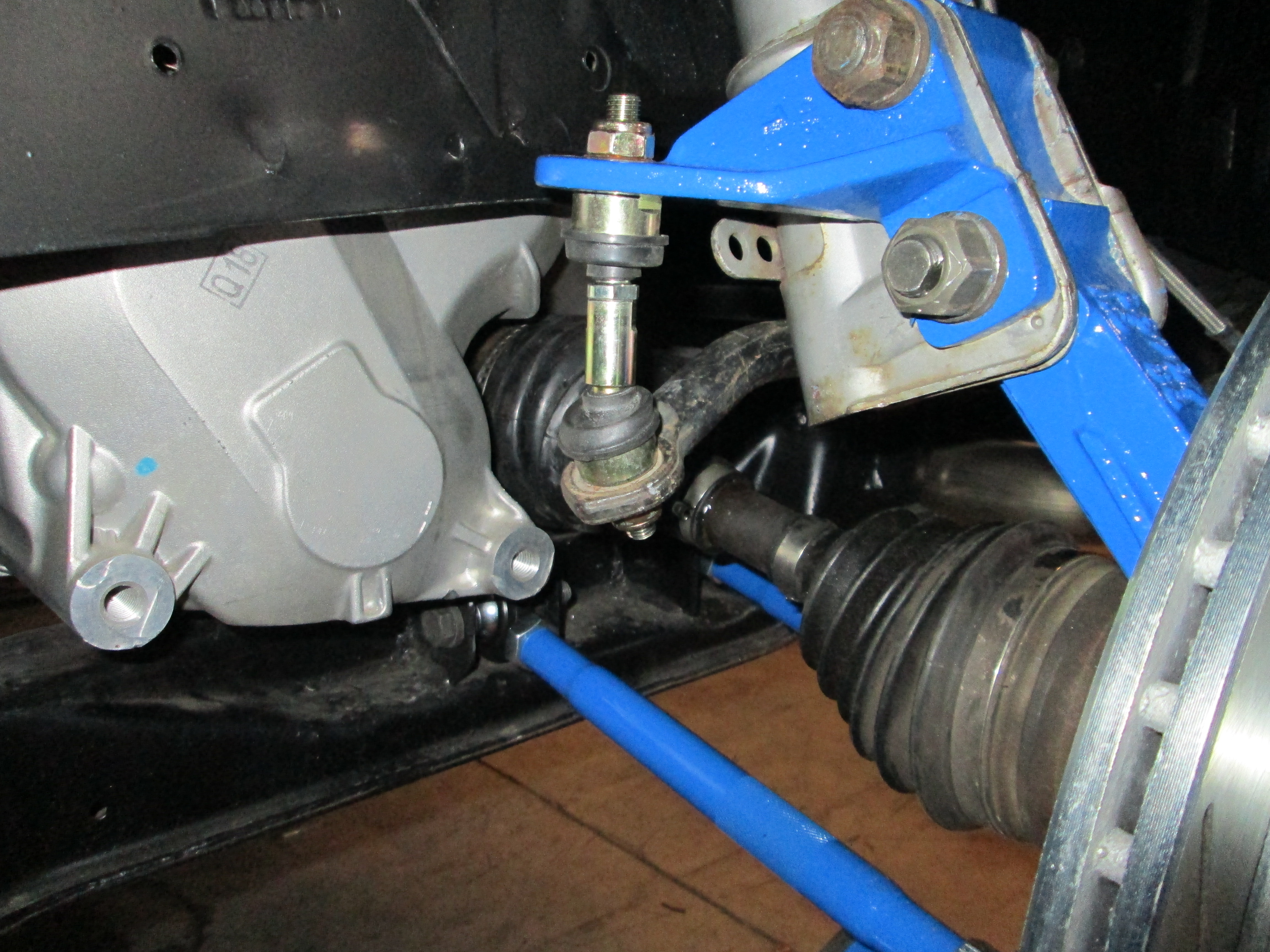
Here are some rear suspension installation pics:
Then I removed the sliders and cleaned/lubed them up and reassembled.
Caliper adapter bracket installed:
Rotor, caliper and pads installed:
Tucked behind the 16x7 wheel... very, very tight!
Here is a picture of Rodney's zero lash sway bar links:
I had to rework the upper spring perch for the new springs (wouldn't fit inside the 3 1/2" tube, so I have to make the sleeve internal):
Here I compressed the strut to ensure the inner sleeve would clear the coil over sleeve and it does:
Here are some rear suspension installation pics:
03-02-2013, 07:44 PM
#117
The front is now lowered (front spring cut 1"), the bump stops trimmed 1 1/4", Koni shocks installed, Rodney's zero lash rod ends installed, my 13" brake kit installed along with braided stainless hoses (I will be revisiting the front to clean it up once the car is running/tuned and while the body panels are off being painted).

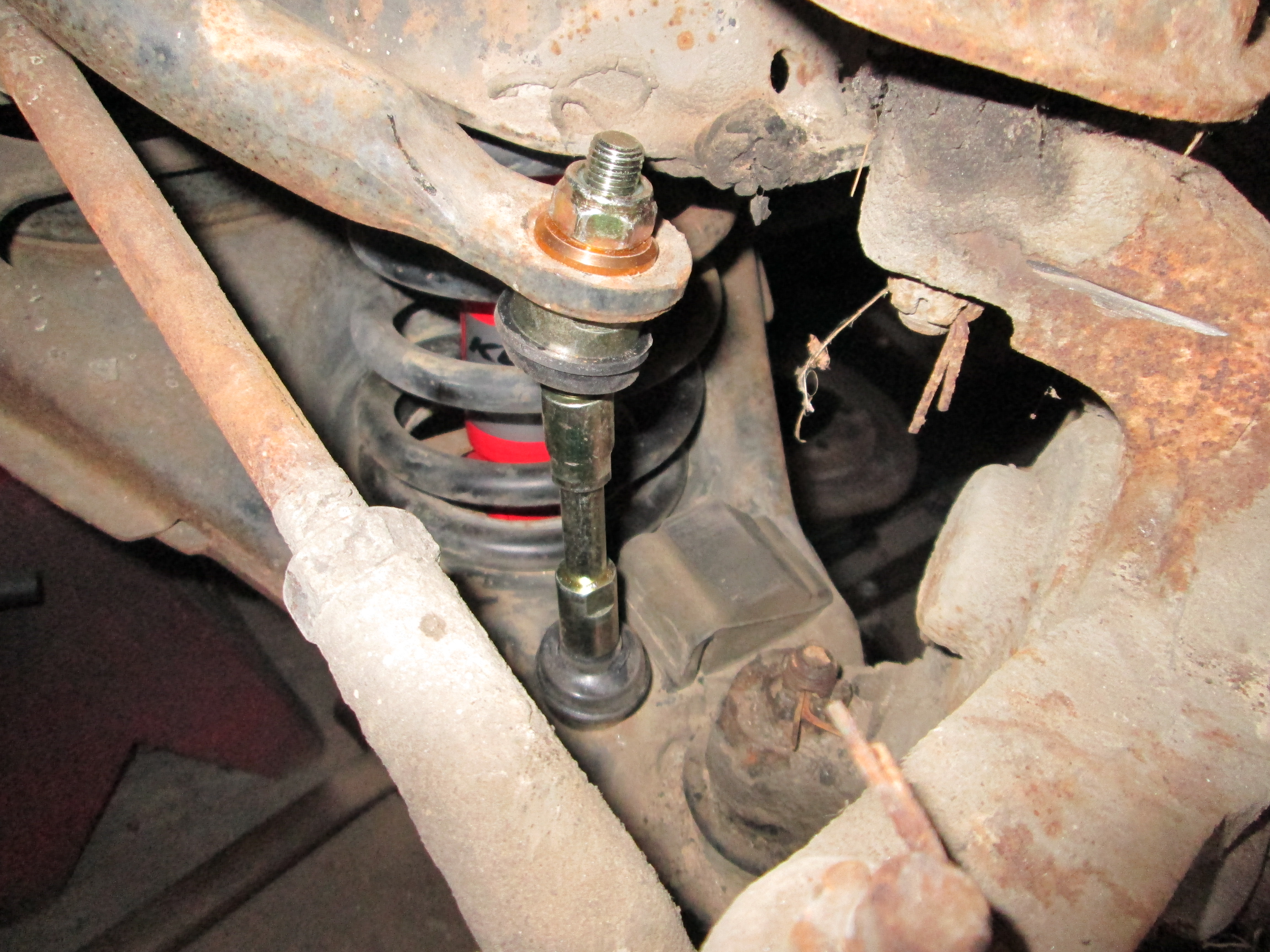
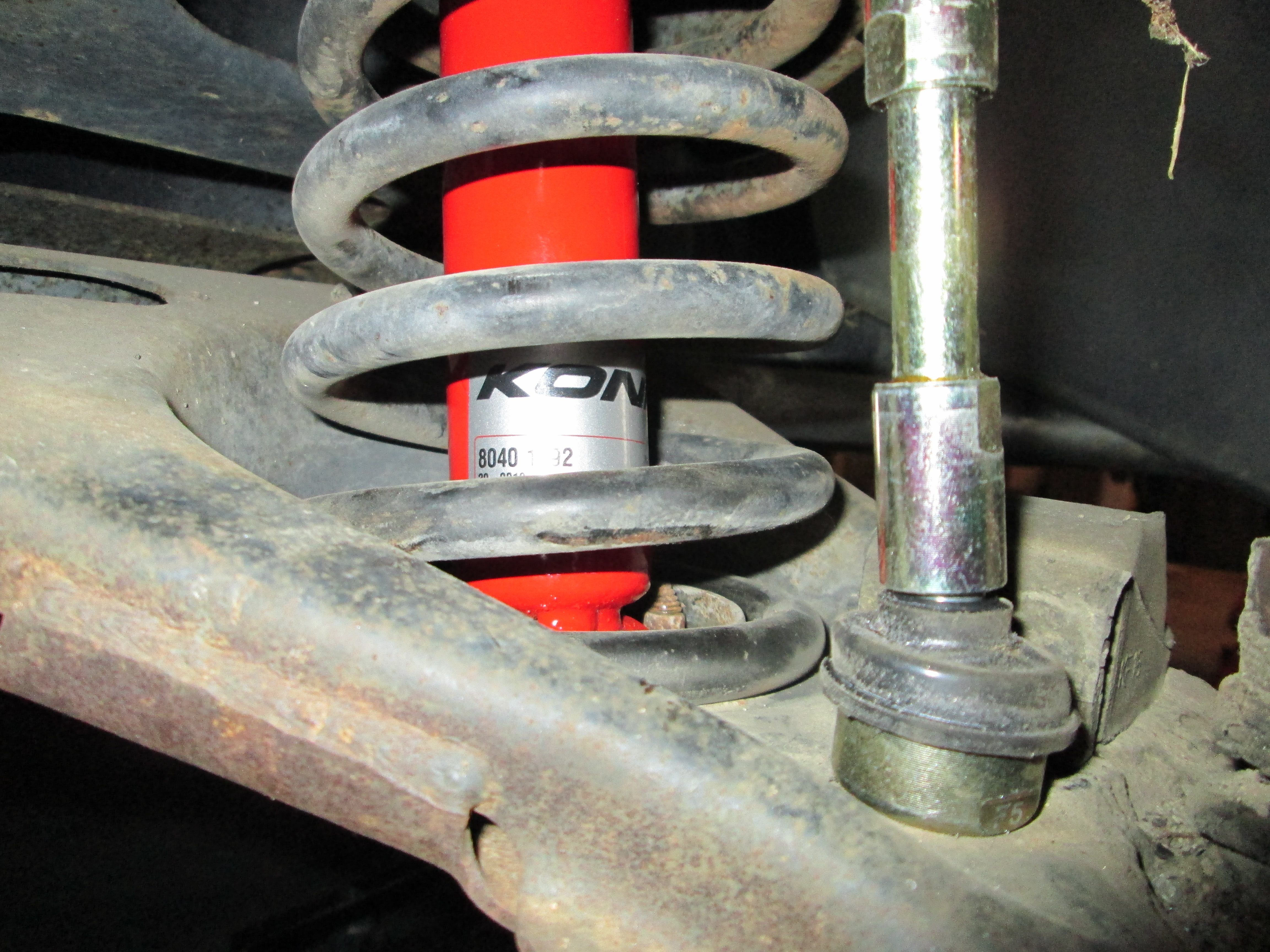
On Sunday I will bleed the brakes and do the alignment.
On Sunday I will bleed the brakes and do the alignment.
03-03-2013, 06:45 PM
#118
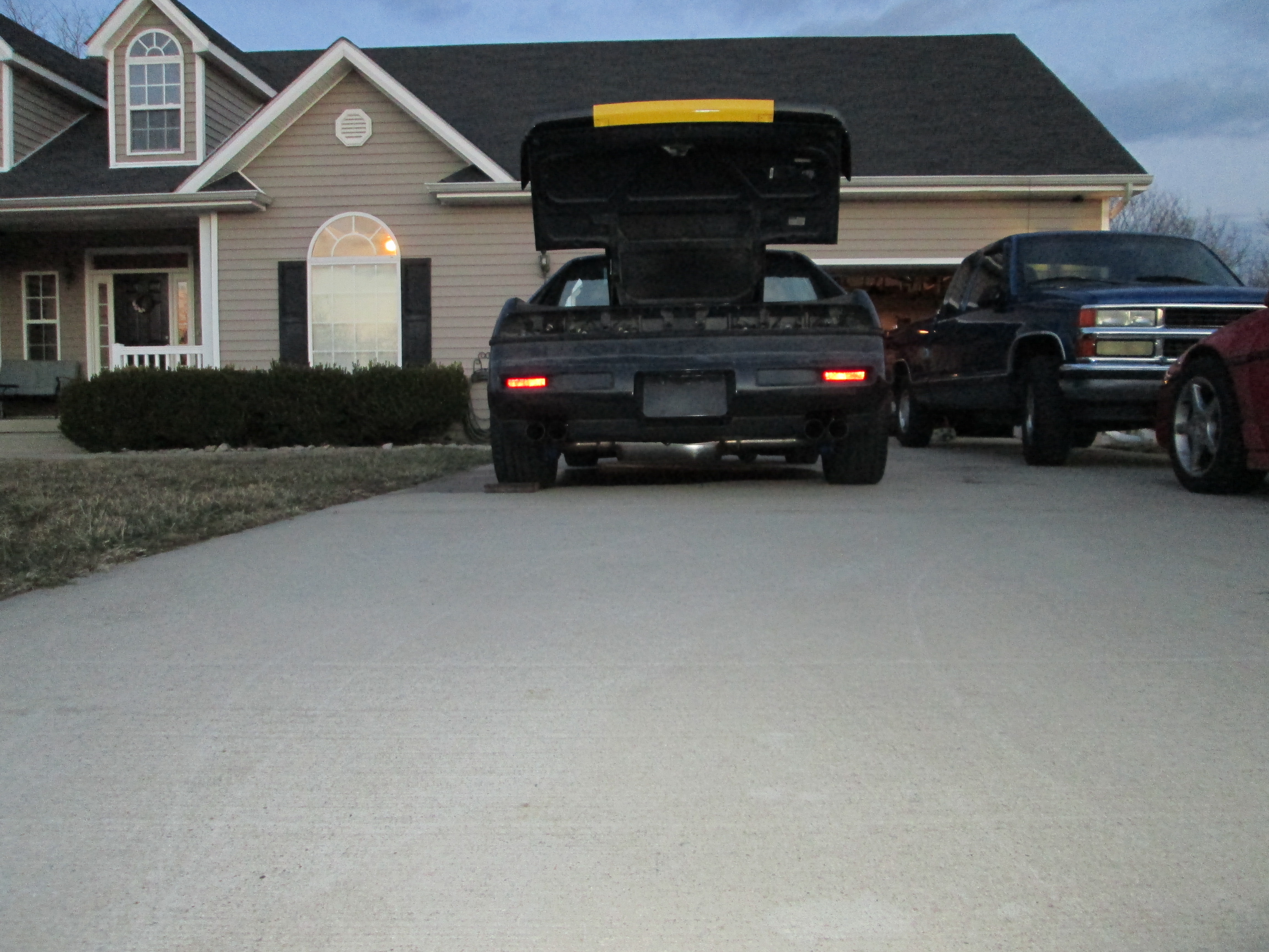
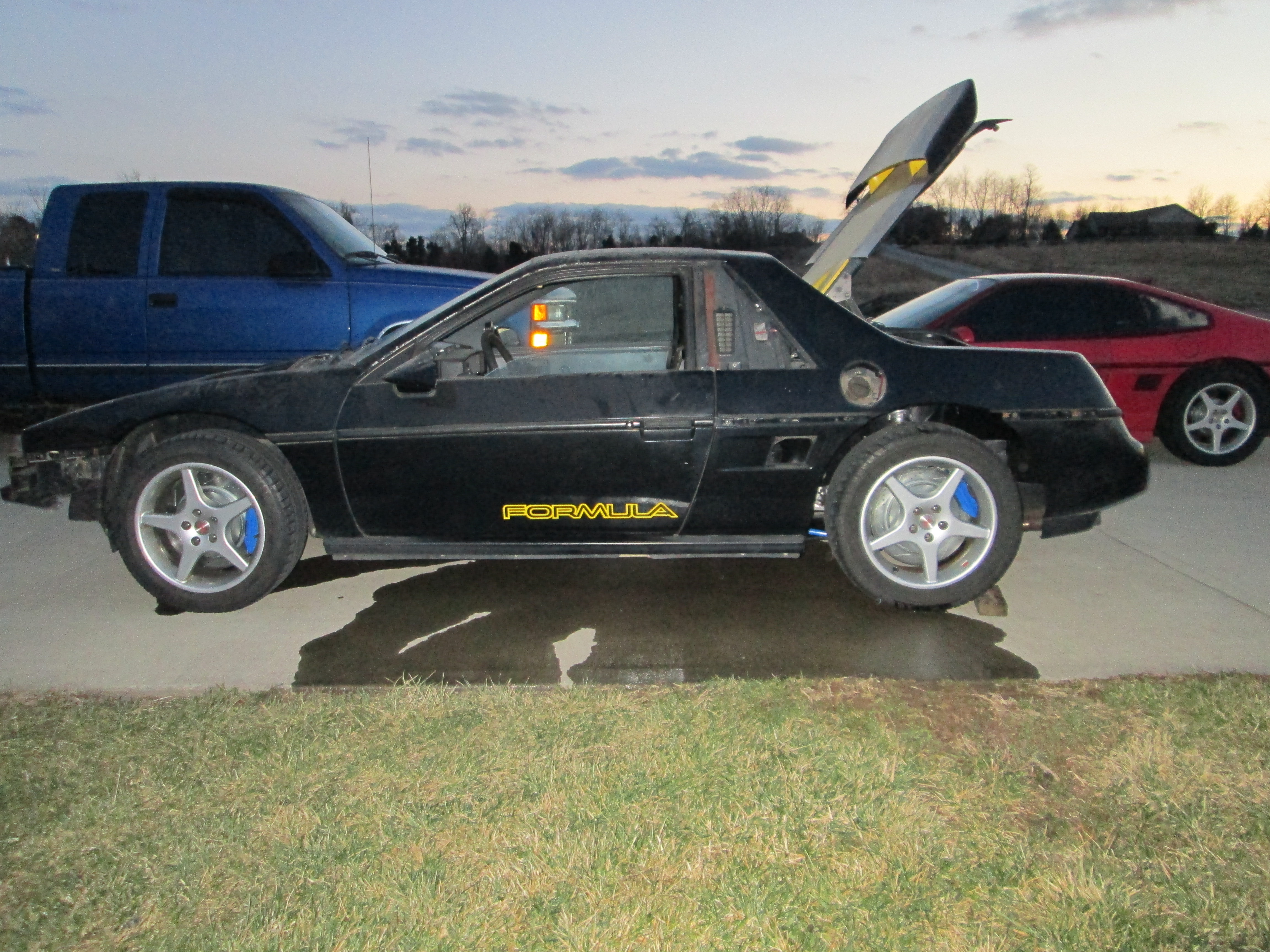
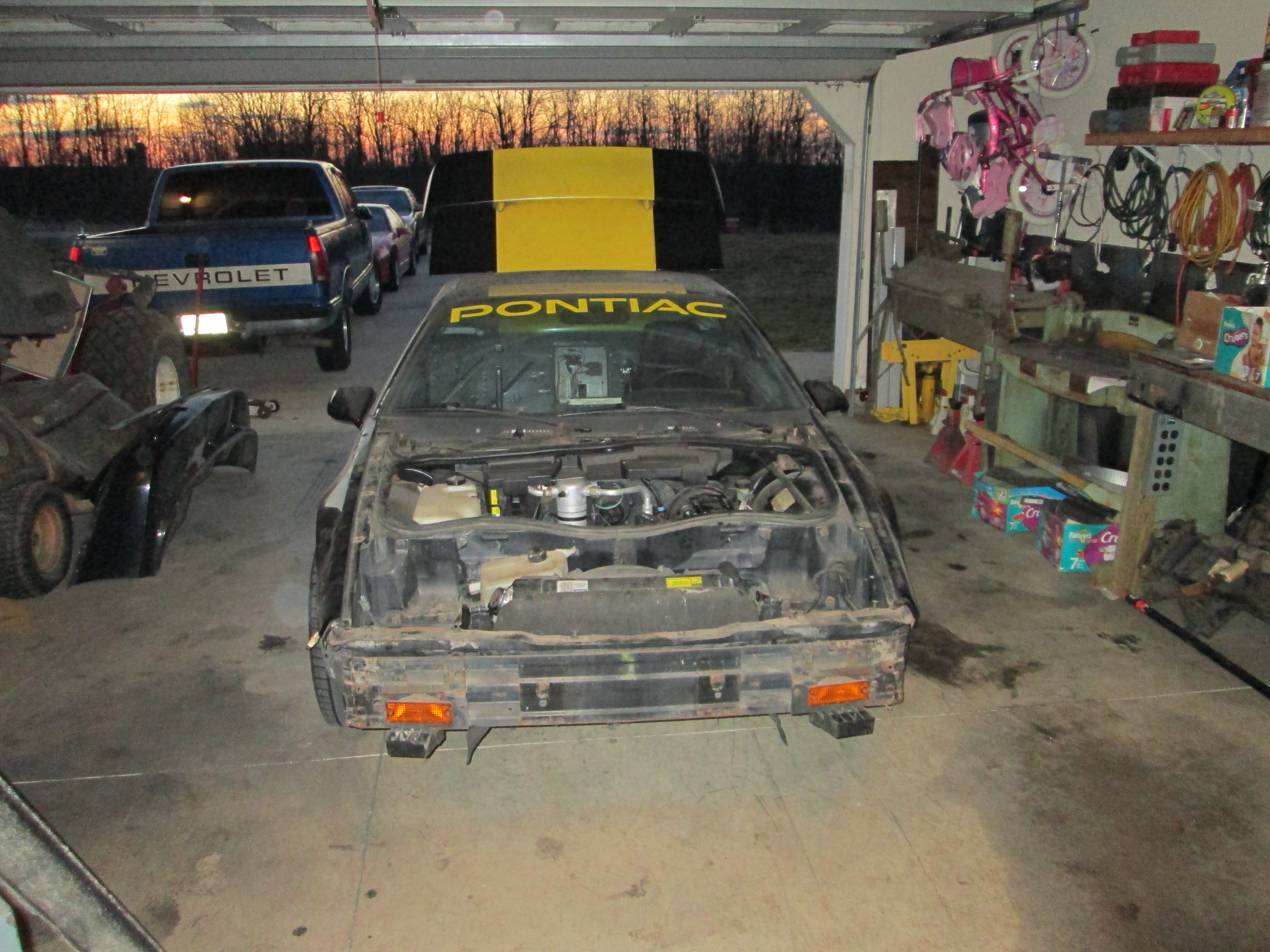
Got the brakes bled (but I need to do it again as there still is some air in them) and the alignment done then took the LS4/F40 Fiero out for a drive down a couple of streets within the subdivision!
Then I had it parked in the driveway doing the 2 hr idle test (I let the engine idle for 2 hrs constant to verify coolant system, fan action, etc)... well there is a reason I do this test, it is so any issue will happen while it is parked in the drive. One of the radiator hoses decided to come off and dump antifreeze on the driveway... so that ended my fun for the day.

The squealing from a bad bearing is really getting annoying. Since the coolant system is mostly empty (water pump inlet hose is the one that came off), I went ahead and ordered a new A/C Delco water pump with a cast iron impeller (vs. spot welded sheet metal) and it should be here Tuesday.
During my drive I noticed that the Tach and Speedo are inoperable (temp and oil pressure work). Both work in the scan tool, so its and issue between the ECM and gauges. Both of these I wired up at the pin locations used in the TBSS/CTSV E67 applications hoping the signal was there, just not used in the LS4 calibration. I still need to test adding a 12V signal booster to the tach, but I might need to run a Dakota Digital speedo converter for the factory gauge (and keep the VSS going directly to the ECM for it).
It has been a while since I drove a stick, and the F40 gear spacing will take some getting used to.
Good news is the clutch is easy to modulate and chatter free!
Then I had it parked in the driveway doing the 2 hr idle test (I let the engine idle for 2 hrs constant to verify coolant system, fan action, etc)... well there is a reason I do this test, it is so any issue will happen while it is parked in the drive. One of the radiator hoses decided to come off and dump antifreeze on the driveway... so that ended my fun for the day.
The squealing from a bad bearing is really getting annoying. Since the coolant system is mostly empty (water pump inlet hose is the one that came off), I went ahead and ordered a new A/C Delco water pump with a cast iron impeller (vs. spot welded sheet metal) and it should be here Tuesday.
During my drive I noticed that the Tach and Speedo are inoperable (temp and oil pressure work). Both work in the scan tool, so its and issue between the ECM and gauges. Both of these I wired up at the pin locations used in the TBSS/CTSV E67 applications hoping the signal was there, just not used in the LS4 calibration. I still need to test adding a 12V signal booster to the tach, but I might need to run a Dakota Digital speedo converter for the factory gauge (and keep the VSS going directly to the ECM for it).
It has been a while since I drove a stick, and the F40 gear spacing will take some getting used to.
Good news is the clutch is easy to modulate and chatter free!
03-04-2013, 07:17 AM
#119
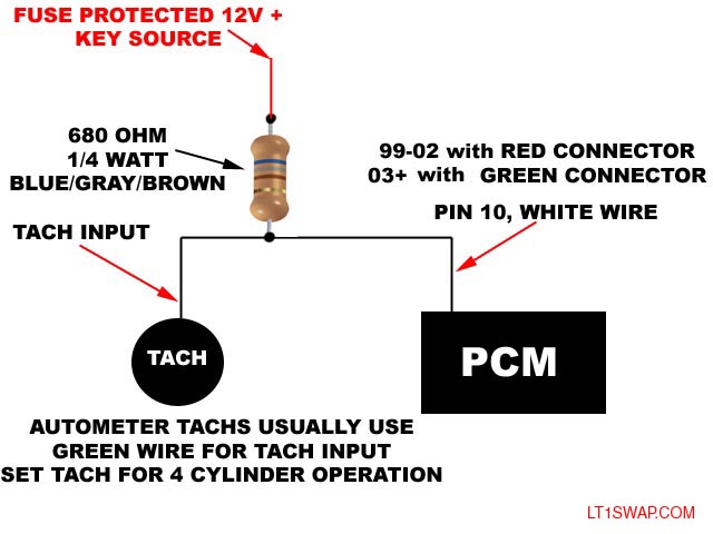
The tach now works!
I had 2 things wrong. First within the calibration: Engine/Tach Output/Tach Type: you have 3 choices. Serial (which is what the LS4 uses), Frequency (which is what the TBSS uses) and Crank (which is what the CTSV uses). I had set it to frequency, but when I added the booster circuit the tach still didn't move. So I switched it to Crank and with the booster circuit the tach sprang to life (I still need to calibrate it for V8 vs V6). Here is the booster circuit that I found used on the LS1's and appear to work on the E67 as well:
I don't know if the Speedo is fixed yet, but I found an issue in the calibration setting for it as well. Under Speedo/Vehicle Speed Output, Output Source: you have 3 settings again. Disabled (which is what the LS4 used, and where I still had it), RepTOS and Serial. I doubt having the VSS output signal disabled was correct, but still don't know if RepTOS or Serial will allow it to work with the normal speedo buffer circuit. I have it set to RepTOS now.
While I was going to do a reflash anyway, I went ahead and turned off Dynamic Airflow (speed density) and DFCO so I can run MAF only and start working on the MAF tune. Once I get the MAF dialed in, then I can turn it off and work on tuning Dynamic Airflow using the equation coefficients.