
My First BMW – My First Swap – LS2/T56 into an E36


 12-12-2014, 08:39 PM
#82

I can't win. I played around with the Eastwood tool. It works very well. But I need to flare three lines on the car, and I can't use the Eastwood tool for that.
So, I figured give the Cal-Van 156 a whirl. It's a Metric/ISO kit and the smallest die is 4.75mm, which is the basically same as 3/16". But of the three line clamps included in the 156 kit, the smallest is too large for 3/16". So then I have a brainstorm. Advance carries the Cal-Van 161, which is a double flare tool, but it's sized for 4.75mm - 3 1/16" line. I figured I could use the line clamp from the 161 with the 4.75mm die from the 156 kit. So, off to Advance to pick up the Cal-Van 161.
Obviously, I wanted to give it a try with some scrap line. The line clamp form the 161 kit worked but my first attempt resulted in a really ugly, lopsided flare. The second attempt? The threads on the damn line clamp stripped!
So now I'm stuck because I really need to make three flares on the car and I think the only way I'm going to get that done at this point is to get my hands on a Mastercool hydraulic flaring tool. I just spent $200 on the Eastwood tool and and I'm not about to spend $300 on another tool to make three flares. Somehow, I need to track one down.
Tipsy
12-13-2014, 07:06 PM
#83
Staging Lane
Join Date: Jun 2013
Location: Austin, TX
Posts: 69
Likes: 0
Received 0 Likes
on
0 Posts
I used the Eastwood tool under the car. I used a big pipe wrench with a long pipe on the handle instead of a bench vise to hold the base. Wasn't easy but it worked. I did put a nice dent in my forehead when the pipe slipped the first time though, adjusted my technique and no other issues.
I thought about welding up some kind of frame to put it in that I could lay on to hold/leverage the flaring tool but didn't take the time to do it.
I thought about welding up some kind of frame to put it in that I could lay on to hold/leverage the flaring tool but didn't take the time to do it.
12-14-2014, 10:08 AM
#84
I used the Eastwood tool under the car. I used a big pipe wrench with a long pipe on the handle instead of a bench vise to hold the base. Wasn't easy but it worked. I did put a nice dent in my forehead when the pipe slipped the first time though, adjusted my technique and no other issues.
I thought about welding up some kind of frame to put it in that I could lay on to hold/leverage the flaring tool but didn't take the time to do it.
I thought about welding up some kind of frame to put it in that I could lay on to hold/leverage the flaring tool but didn't take the time to do it.
It'll have to wait till next year though. I'm traveling 'til then.
Tipsy
12-15-2014, 11:33 AM
#85
Jeez man. You can't win!
If you already have the old 25$ kit, try some of the suggestions that I wrote up earlier. You can still produce a quality flare with those kits, it just takes some more prep work to get it perfect.
Doug
If you already have the old 25$ kit, try some of the suggestions that I wrote up earlier. You can still produce a quality flare with those kits, it just takes some more prep work to get it perfect.
Doug
12-15-2014, 01:29 PM
#86
TECH Resident

Use copper nickel brake lines. Source from Amazon or ebay. they are WAY easier to form than anything more steel based. Look great too. Kind of a gold titanium color.
25' isn't more than $30 shipped through Amazon Prime.
That material flares great, too! Many Euro OEMs have use these, including Porsche.
Doug
25' isn't more than $30 shipped through Amazon Prime.
That material flares great, too! Many Euro OEMs have use these, including Porsche.
Doug
12-15-2014, 02:04 PM
#87
Use copper nickel brake lines. Source from Amazon or ebay. they are WAY easier to form than anything more steel based. Look great too. Kind of a gold titanium color.
25' isn't more than $30 shipped through Amazon Prime.
That material flares great, too! Many Euro OEMs have use these, including Porsche.
Doug
25' isn't more than $30 shipped through Amazon Prime.
That material flares great, too! Many Euro OEMs have use these, including Porsche.
Doug
For those reasons, I opted to stick with Poly Armour.
Tipsy
12-15-2014, 02:28 PM
#88
TECH Resident
Hi Tipsy,
You did more research than I. I've successfully plumbed several (metric w/ bubble flares) cars with the nicopp product and the eastwood tool. They turned out great.
Good luck!
Doug
You did more research than I. I've successfully plumbed several (metric w/ bubble flares) cars with the nicopp product and the eastwood tool. They turned out great.
Good luck!
Doug
03-07-2015, 01:16 PM
#91
Rolled under the car and determined there's no way I'm removing the rear brake lines from the car. At a minimum, the fuel tank needs to come out. And possibly the entire rear suspension. While I do want to/need to remove the rear at some point to replace all the bushings, it's not something I want to tackle right now while the car is 16" off the ground.
So, I did the best I could and connected the existing lines to the new lines. It's not going to win any awards but I think/hope it will do the trick. I replaced all of the lines I'd previously made, with the exception of one. I used the new Eastwood flaring tool. It's SO much better than the auto store Chinese crap I used the first time. There are a couple a very slight kinks from wrestling with the rear lines, but I don't think they'll be an issue. Right now, I'm really anxious to get the hydroboost and master cylinder installed so I can get fluid in the system and check for leaks.
Pics:
03-07-2015, 01:28 PM
#92
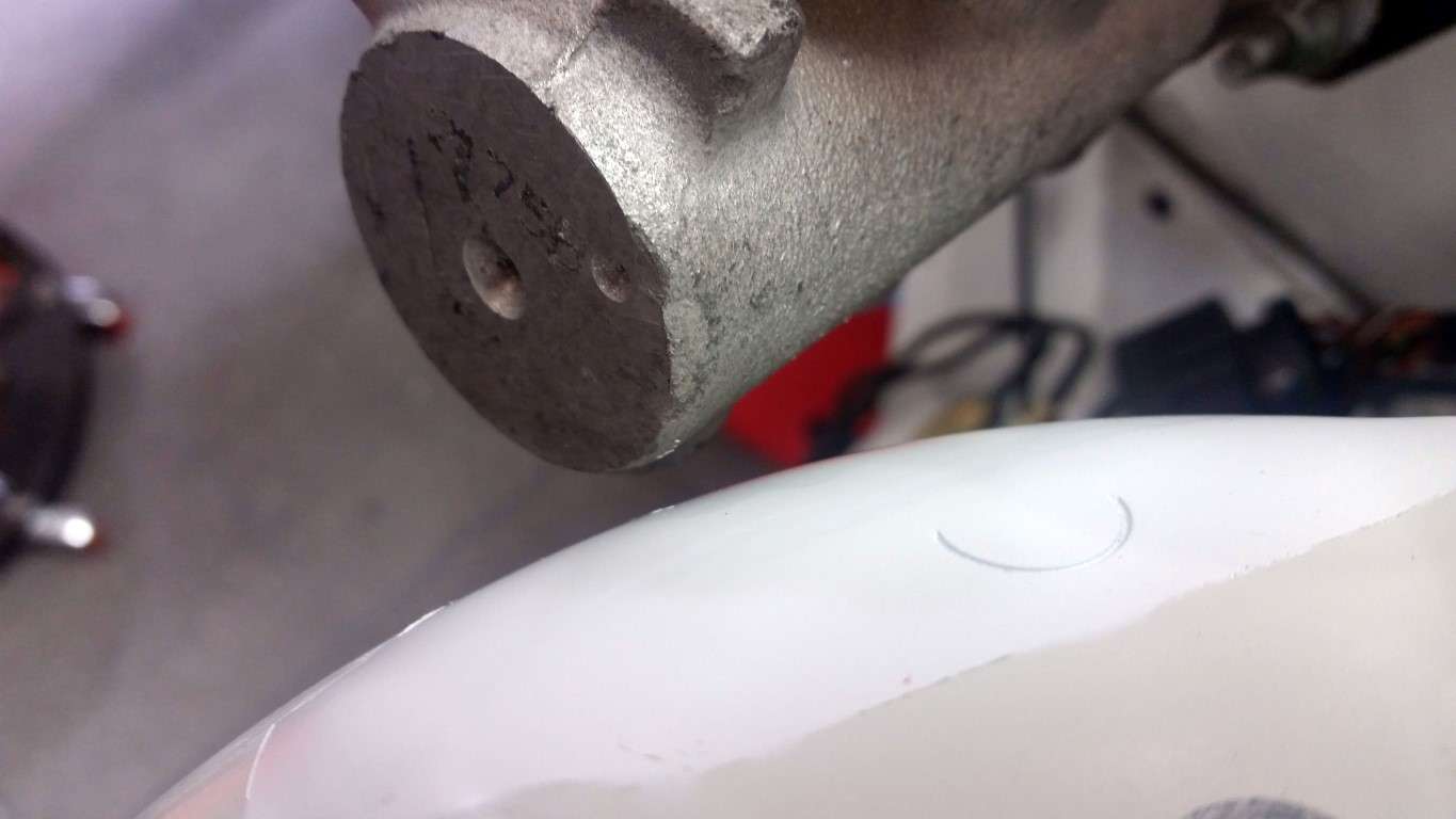
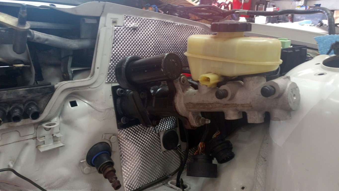
Minor forward momentum; the hydroboost is bolted in. It clears the strut tower by nearly 1/4"! However, I have serious doubts that I'd be able to remove the master cylinder from the booster without removing the entire assembly from the car. I could be wrong, but it looks like one of the two bolts that secures the master to the booster stays in place, which would necessitate sliding the master forward at least a couple of inches to separate it from the booster. That's not going to happen with the strut tower there. Hopefully, this used eBay hydroboost/master cylinder (2004 Mustang) will work as desired and it won't be an issue.
The with electrical connectors snapped into place on the fuse box, the x6031 connector is in contact with the a low pressure fitting on the hydroboost. I guess I'll just have to let the connectors "float."
Booster Installed

Booster Bracket
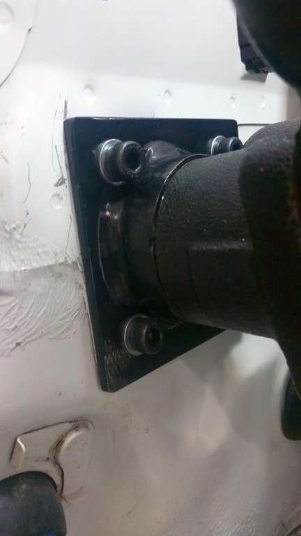
Strut Tower Clearance
Low Pressure Fitting & X6031 Connector
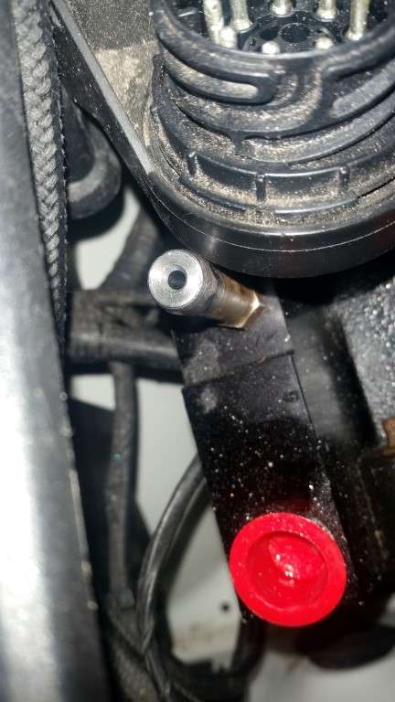
The with electrical connectors snapped into place on the fuse box, the x6031 connector is in contact with the a low pressure fitting on the hydroboost. I guess I'll just have to let the connectors "float."
Booster Installed
Booster Bracket
Strut Tower Clearance
Low Pressure Fitting & X6031 Connector
Last edited by TipsyMcStagger; 11-15-2015 at 08:00 PM.
03-07-2015, 01:51 PM
#93
Minor forward momentum; the hydroboost is bolted in. It clears the strut tower by nearly 1/4"! However, I have serious doubts that I'd be able to remove the master cylinder from the booster without removing the entire assembly from the car. I could be wrong, but it looks like one of the two bolts that secures the master to the booster stays in place, which would necessitate sliding the master forward at least a couple of inches to separate it from the booster. That's not going to happen with the strut tower there. Hopefully, this used eBay hydroboost/master cylinder (2004 Mustang) will work as desired and it won't be an issue.
03-09-2015, 07:05 PM
#95
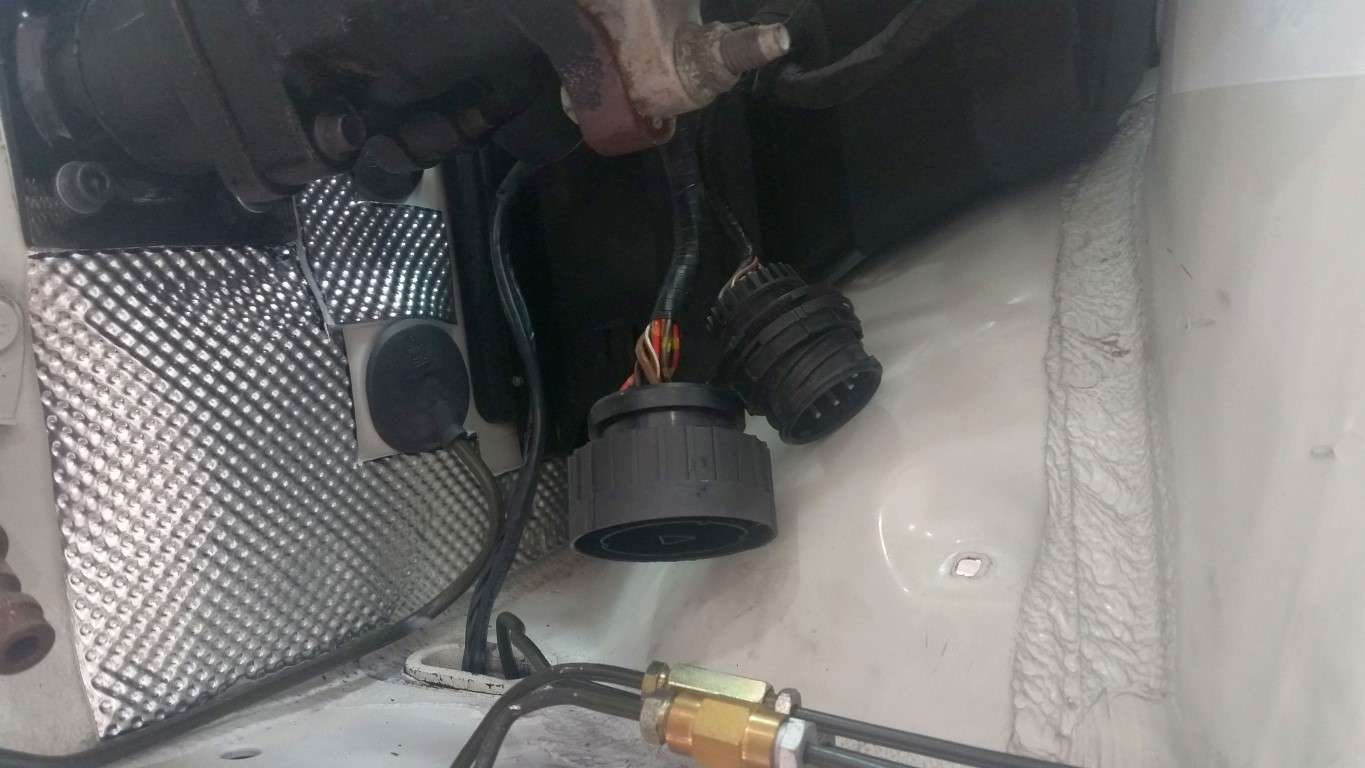
I decided to cut the bracket that secures the harness connectors to the fuse box. I'm not 100% sure but I don't think there are many wires in the x6031 connector that I'll be using, if any. It's just hanging below the hydroboost and I don't see any problem with leaving it there.
I started to get the DEI heat shield on the firewall. It's definitely time consuming making the templates. I ended up making the piece by the brake booster out of several small pieces. There are seams, but I don't think it's a big deal. I'll probably put more heat shield at the top of the tunnel and around the steering column tomorrow, but I'm going to hold off applying it to the tunnel until I've had a chance to test fit the engine.
Tipsy
x6031 Cut From Bracket

x6031 and ABS Connector
Heat Shield
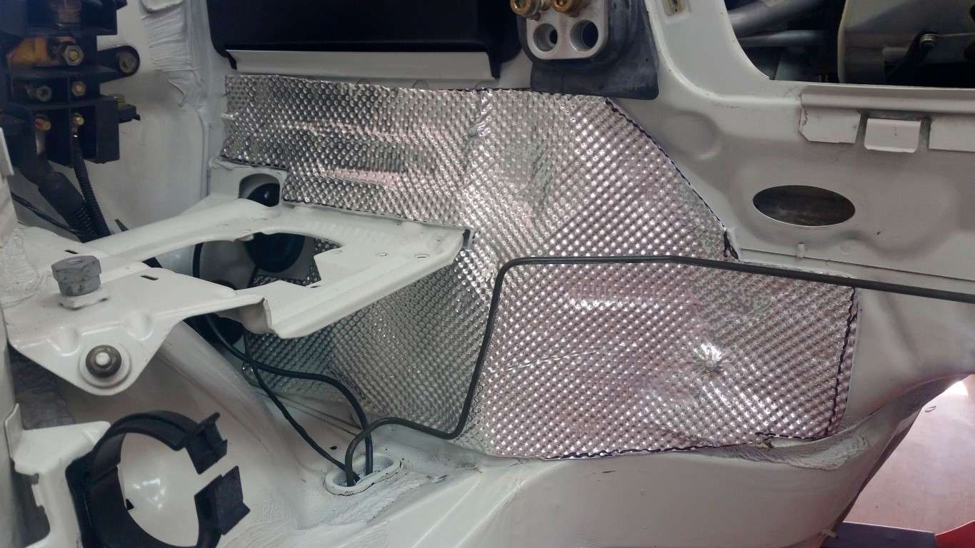
More Heat Shield
I started to get the DEI heat shield on the firewall. It's definitely time consuming making the templates. I ended up making the piece by the brake booster out of several small pieces. There are seams, but I don't think it's a big deal. I'll probably put more heat shield at the top of the tunnel and around the steering column tomorrow, but I'm going to hold off applying it to the tunnel until I've had a chance to test fit the engine.
Tipsy
x6031 Cut From Bracket
x6031 and ABS Connector
Heat Shield
More Heat Shield
Last edited by TipsyMcStagger; 11-15-2015 at 08:15 PM.
03-09-2015, 07:06 PM
#96
We all know I don't work very fast and I'm not ashamed to say I spent most of today making an ABS extension harness (along with two visits to Home Depot). I'm glad I bought a bunch of extra harness connectors at the pick-n-pull. Having extras allowed me to pilfer heavier gauge wiring from several connectors as well as those little rubber plugs for the unused pin positions.
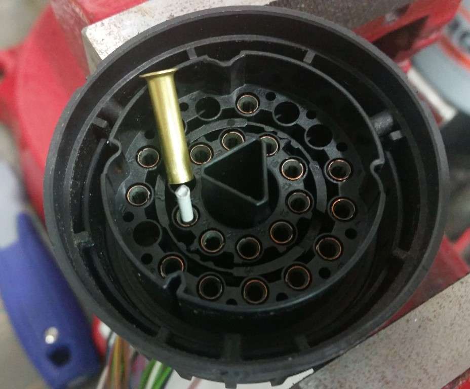
Thanks to those who have gone before me, I headed to the plumbing aisle and picked up a Watts 1/4” OD compression fitting (A-4 961-P) to use as a pin removal tool, in lieu of the $70+ tool BMW sells. It worked perfectly.
Watts A-4 961-P
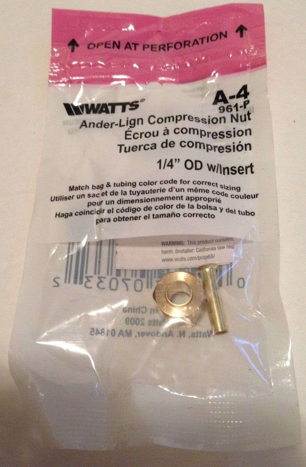
There was some mention of needing to sand the fitting for better fitment, but I didn't see the need. Here are a few tips I'll add. Firstly, there is a locking ring in both the male and female connectors that needs to be, well, unlocked. It spins about 1/4” or less using a small screwdriver or awl. Most of these rings are black but here's a connector with a grey ring, which is easier to decipher:
Locking Ring

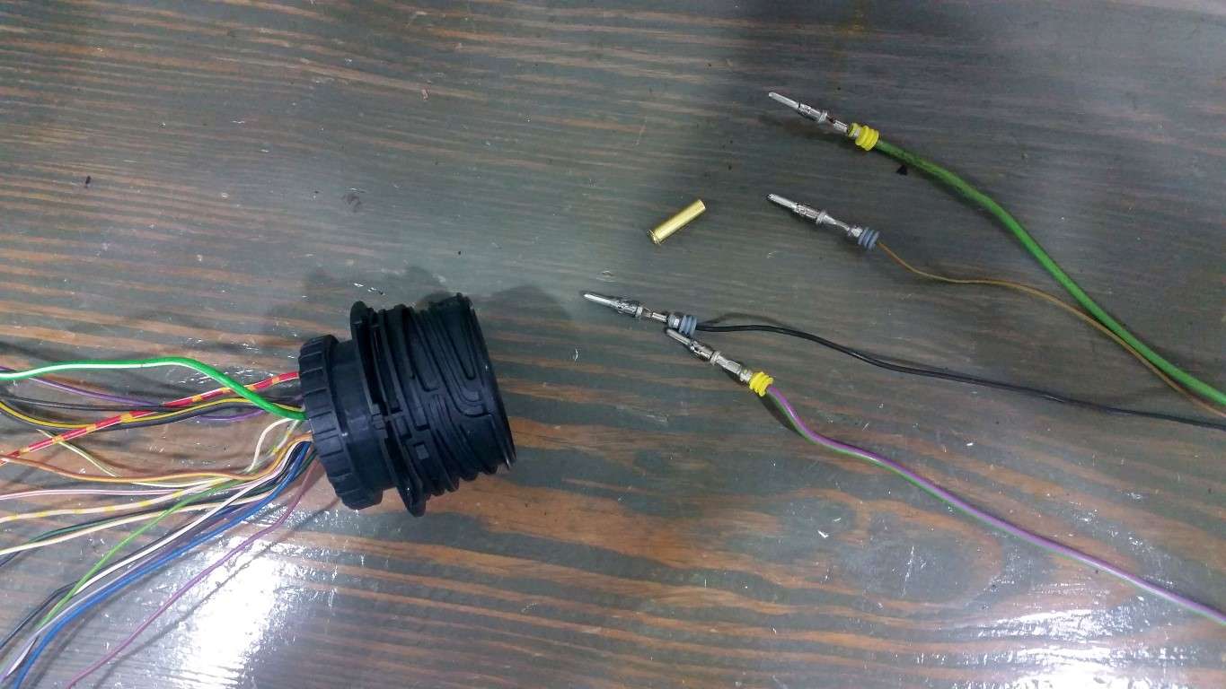
The male pins are a no-brainer. Slip the little compression fitting over the pin and (after making sure you've unlocked the retaining ring) push against something, like your workbench, and Presto! The pin will pop right out!
Pins Removed
The female pins were a bit more of a challenge initially because it's difficult to hold the compression fitting against the “face” of the female pin (they are both effectively the same diameter). But that was quickly overcome by simply inserting a small piece of wire coat hanger into the pin. The compression fitting now has something to hold onto while you press against your work bench.
Wire hanger in female pin:
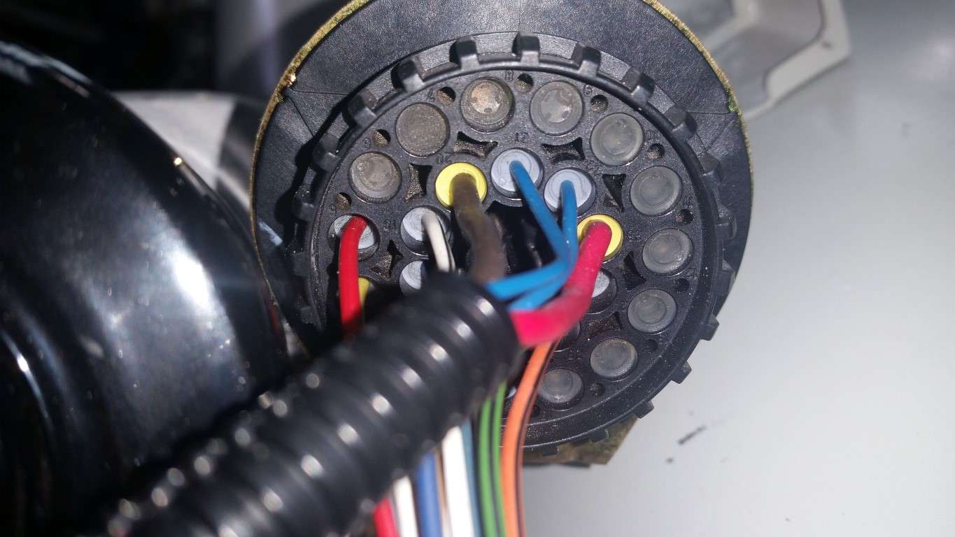
The yellow grommets are definitely used on wires of a heavier gauge. What's strange is that the chassis side connector has four “heavier” wires (four yellow grommets) while the connector on the ABS pump only has two. You'd think the wire gauge would be consistent from the chassis to the pump, no? At any rate, I removed pins from my spare x20 connectors, eliminated unneeded wires and inserted heavier gauge (yellow grommet) wires where needed.
Chassis Side Connector
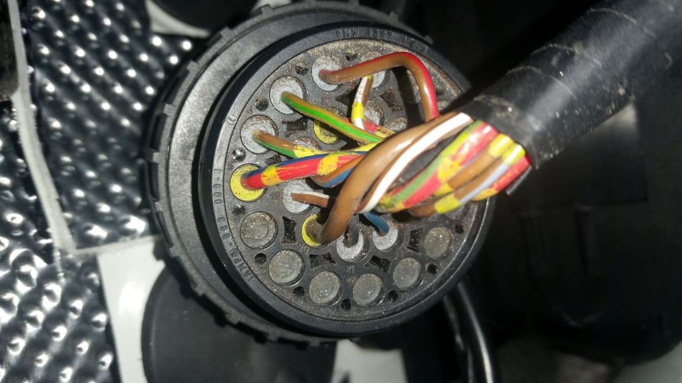
ABS Connector
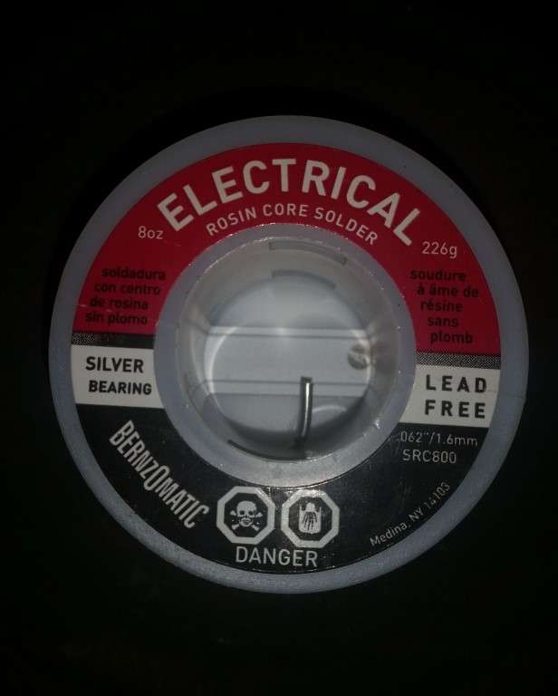
Once that was done, it was time to solder. And that's where I ran into some problems. I have no idea why, but I just couldn't get the solder to flow - at all. I used a quality Weller 100+ watt soldering gun, keeping the tip clean and tinned. I heated the wire and tried to apply the solder to the hot wire (not to the gun) but it simply wouldn't flow. And when it would melt, it would just glob up. Needless to say, I'm not too happy with the solder joints but they should be good enough. I tested all of the pins for continuity during and after.
I don't know what's up the solder. Have you guys ever had issues getting solder to flow on OEM BMW wire?
Tipsy
Solder
Splice

Ugly Soldered Splice
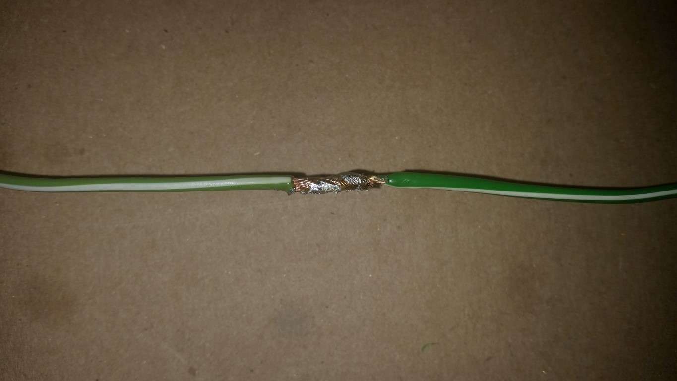
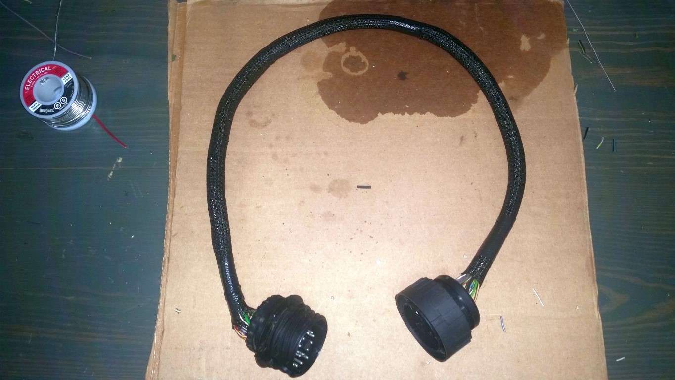
All soldered with marine adhesive heat shrink

Wrapped in 1/2" Techflex F6
Thanks to those who have gone before me, I headed to the plumbing aisle and picked up a Watts 1/4” OD compression fitting (A-4 961-P) to use as a pin removal tool, in lieu of the $70+ tool BMW sells. It worked perfectly.
Watts A-4 961-P
There was some mention of needing to sand the fitting for better fitment, but I didn't see the need. Here are a few tips I'll add. Firstly, there is a locking ring in both the male and female connectors that needs to be, well, unlocked. It spins about 1/4” or less using a small screwdriver or awl. Most of these rings are black but here's a connector with a grey ring, which is easier to decipher:
Locking Ring
The male pins are a no-brainer. Slip the little compression fitting over the pin and (after making sure you've unlocked the retaining ring) push against something, like your workbench, and Presto! The pin will pop right out!
Pins Removed
The female pins were a bit more of a challenge initially because it's difficult to hold the compression fitting against the “face” of the female pin (they are both effectively the same diameter). But that was quickly overcome by simply inserting a small piece of wire coat hanger into the pin. The compression fitting now has something to hold onto while you press against your work bench.
Wire hanger in female pin:
The yellow grommets are definitely used on wires of a heavier gauge. What's strange is that the chassis side connector has four “heavier” wires (four yellow grommets) while the connector on the ABS pump only has two. You'd think the wire gauge would be consistent from the chassis to the pump, no? At any rate, I removed pins from my spare x20 connectors, eliminated unneeded wires and inserted heavier gauge (yellow grommet) wires where needed.
Chassis Side Connector
ABS Connector
Once that was done, it was time to solder. And that's where I ran into some problems. I have no idea why, but I just couldn't get the solder to flow - at all. I used a quality Weller 100+ watt soldering gun, keeping the tip clean and tinned. I heated the wire and tried to apply the solder to the hot wire (not to the gun) but it simply wouldn't flow. And when it would melt, it would just glob up. Needless to say, I'm not too happy with the solder joints but they should be good enough. I tested all of the pins for continuity during and after.
I don't know what's up the solder. Have you guys ever had issues getting solder to flow on OEM BMW wire?
Tipsy
Solder
Splice
Ugly Soldered Splice
All soldered with marine adhesive heat shrink
Wrapped in 1/2" Techflex F6
Last edited by TipsyMcStagger; 11-15-2015 at 08:26 PM.
03-11-2015, 07:20 PM
#97
I started the day wresting and sweating with this Harbor Freight "Single action" strut spring compressor.
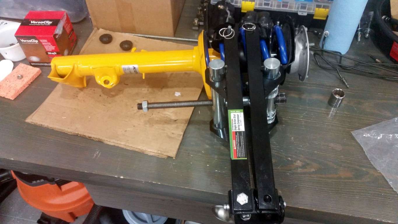
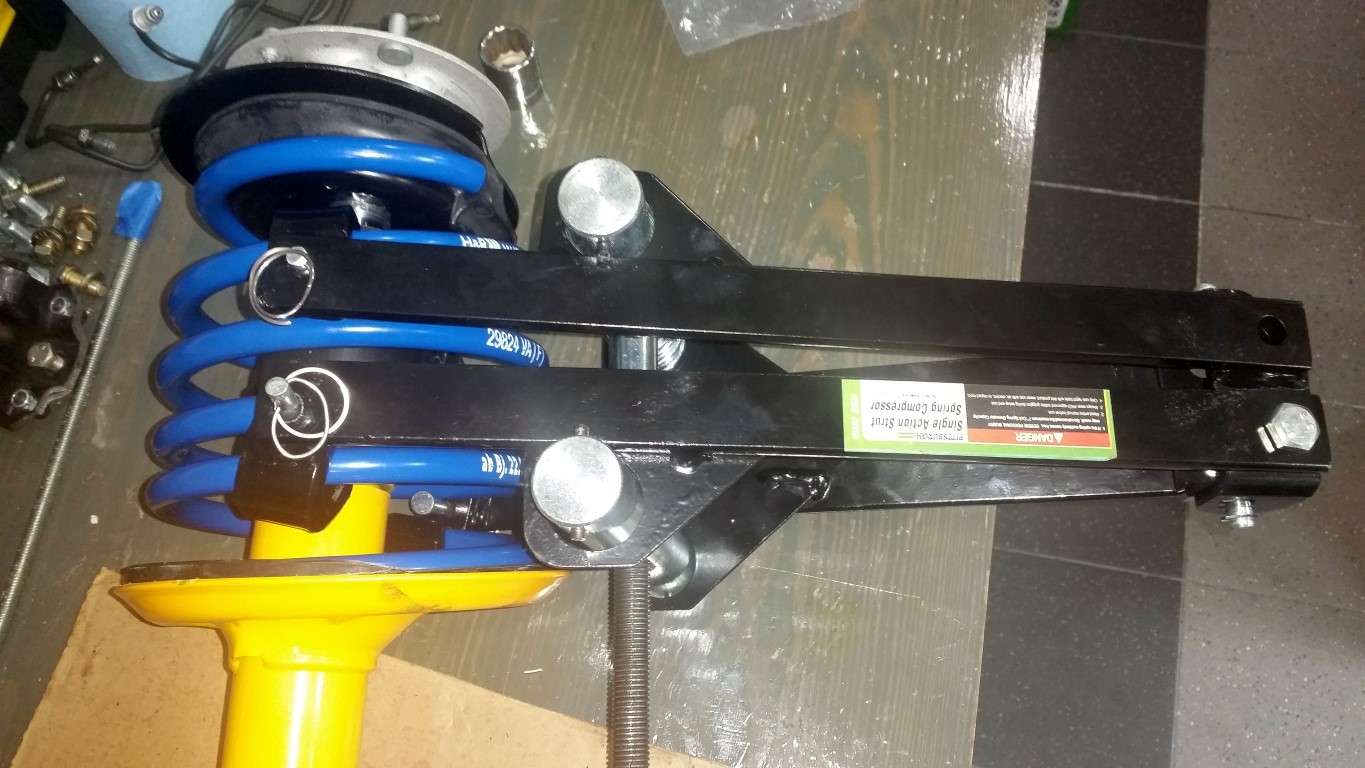
After my first attempt using this tool I thought, "hey, this thing is pretty slick!" That was, until I decompressed the spring and realized the tool was pinched between the spring the the strut base. After three plus, frustrating, sweaty hours and multiple attempts at positioning the compressor on the spring, I simply couldn't get the spring to compress enough to thread the top retaining nut onto the strut. Well, that's not entirely true. I was able to get the nut on one time but then, being that this is my first time messing with struts, I screwed up. While the spring was compressed, I tightened the retaining nut too tight and the spring top plate twisted. I now realize the proper method (assuming you can compress the spring far enough to get the nut on) is to only tighten to nut only so far, remove the spring compressor, install the strut into the car and then, with the weight of the car on the strut, tighten the nut the rest of the way. Live and learn.
Ultimately, I threw in the towel and brought them to the local German car specialist and had him assemble the struts. I also learned, I should have gone to him from the beginning. He had one of those awesome, free standing strut spring compressors; otherwise known as, the right tool for the job! Hey, we all like working on our cars but seriously, there's no reason to struggle with crappy inadequate spring compressors. No exaggeration, he had both done in less than 10 minutes. Lesson learned.
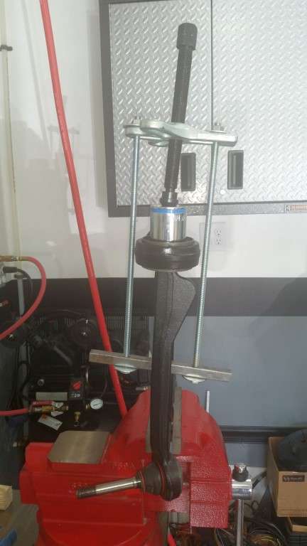
Next was to use my homemade press to install the LCAB brackets onto the control arm (idea stolen from Understeer). Worked perfectly.
LCAB Press:
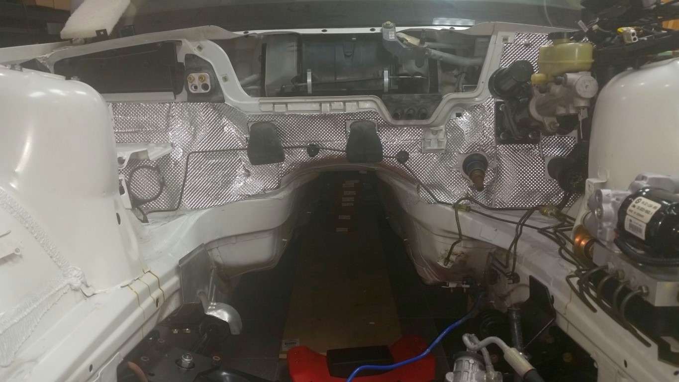
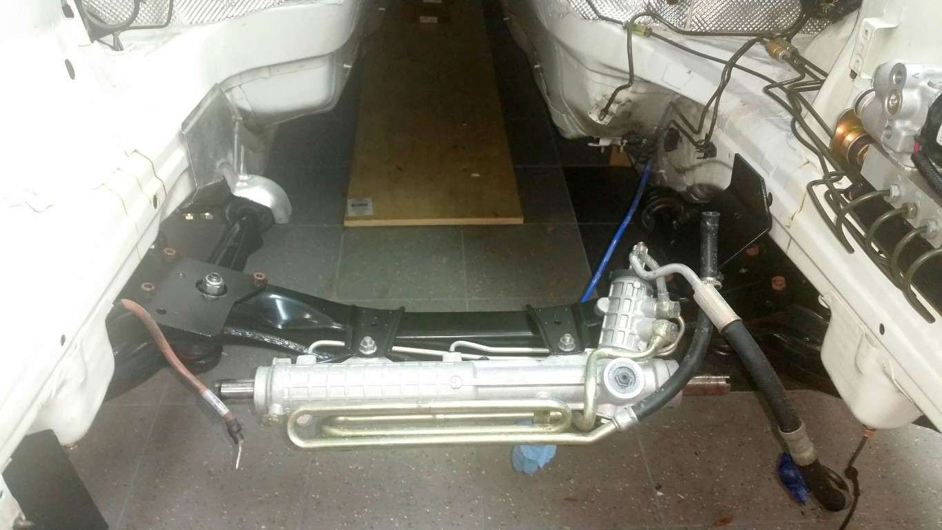
So, the heat shield is applied to the firewall, the subframe and steering rack are installed and both strut assemblies and king pins are installed. Tip from Bimerok: Install the steering rack retaining bolts from the bottom so they can be removed, if need be, with the engine in place.
All I need to do is install the tie rods and I've got a roller!
Tipsy
Firewall Heat Shield
Koni Sport Struts w/ H&R Sport Spring and OEM M3 Reinforcement Plates

Subframe and Steering Rack
After my first attempt using this tool I thought, "hey, this thing is pretty slick!" That was, until I decompressed the spring and realized the tool was pinched between the spring the the strut base. After three plus, frustrating, sweaty hours and multiple attempts at positioning the compressor on the spring, I simply couldn't get the spring to compress enough to thread the top retaining nut onto the strut. Well, that's not entirely true. I was able to get the nut on one time but then, being that this is my first time messing with struts, I screwed up. While the spring was compressed, I tightened the retaining nut too tight and the spring top plate twisted. I now realize the proper method (assuming you can compress the spring far enough to get the nut on) is to only tighten to nut only so far, remove the spring compressor, install the strut into the car and then, with the weight of the car on the strut, tighten the nut the rest of the way. Live and learn.
Ultimately, I threw in the towel and brought them to the local German car specialist and had him assemble the struts. I also learned, I should have gone to him from the beginning. He had one of those awesome, free standing strut spring compressors; otherwise known as, the right tool for the job! Hey, we all like working on our cars but seriously, there's no reason to struggle with crappy inadequate spring compressors. No exaggeration, he had both done in less than 10 minutes. Lesson learned.
Next was to use my homemade press to install the LCAB brackets onto the control arm (idea stolen from Understeer). Worked perfectly.
LCAB Press:
So, the heat shield is applied to the firewall, the subframe and steering rack are installed and both strut assemblies and king pins are installed. Tip from Bimerok: Install the steering rack retaining bolts from the bottom so they can be removed, if need be, with the engine in place.
All I need to do is install the tie rods and I've got a roller!
Tipsy
Firewall Heat Shield
Koni Sport Struts w/ H&R Sport Spring and OEM M3 Reinforcement Plates
Subframe and Steering Rack
Last edited by TipsyMcStagger; 11-15-2015 at 08:33 PM.
03-13-2015, 12:29 PM
#100

I have been follow your thread and a couple other BMW swaps on the forum.These cars are popping up at an independent service center near me for sale.Most are in the $3000 to $5000 range and appear to be in excellent shape.A few have a price in the $7000 range.Most of them are early to mid 2000.