
My First BMW – My First Swap – LS2/T56 into an E36
 03-13-2015, 12:37 PM
#101


I have been follow your thread and a couple other BMW swaps on the forum.These cars are popping up at an independent service center near me for sale.Most are in the $3000 to $5000 range and appear to be in excellent shape.A few have a price in the $7000 range.Most of them are early to mid 2000.
Tipsy
 03-13-2015, 12:41 PM
#102

 03-14-2015, 08:15 PM
#103
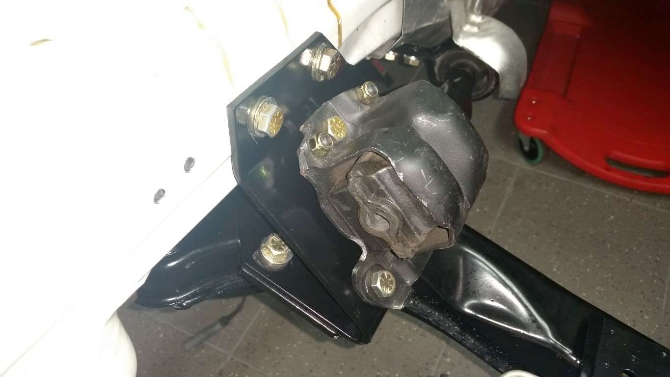
Got the JTR motor mounts installed. This kit uses C4 Corvette rubber mounts that are bridged between the subframe and the frame rail. This is hopefully stronger than mounting only to the subframe. And the rubber isolators should result in minimal NVH transmitted through the chassis. The NVH mitigation is basically the reason I chose to go this route. The drivers side mount is about 1/2" farther forward than the pax side. I played with them a bit and for now, this is the best I could get without pulling them too far forward. The engine side mounts have sliders, so hopefully this will not be an issue.
JTR Mount Installed
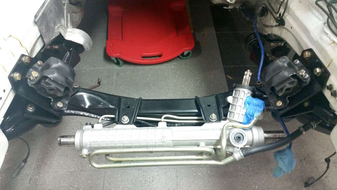
C4 Rubber Mount
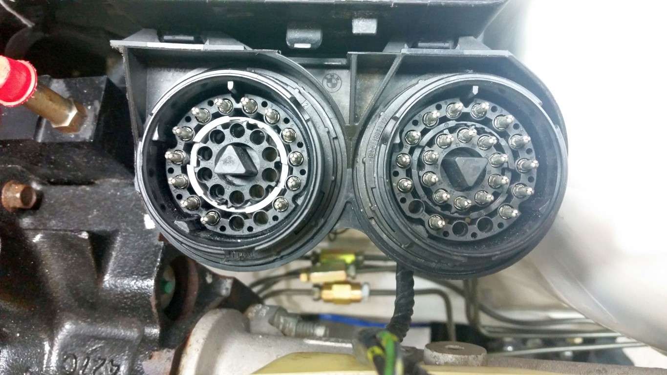
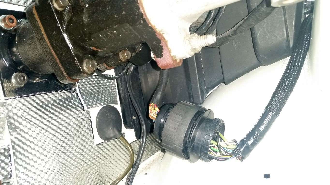
I looked at my notes and there are in fact some pins in the x6031 that I will utilize. After cutting the bracket that holds all three chassis side connectors (because of hydroboost clearance issues), the x6031 was just dangling below the hydroboost (seen blow):
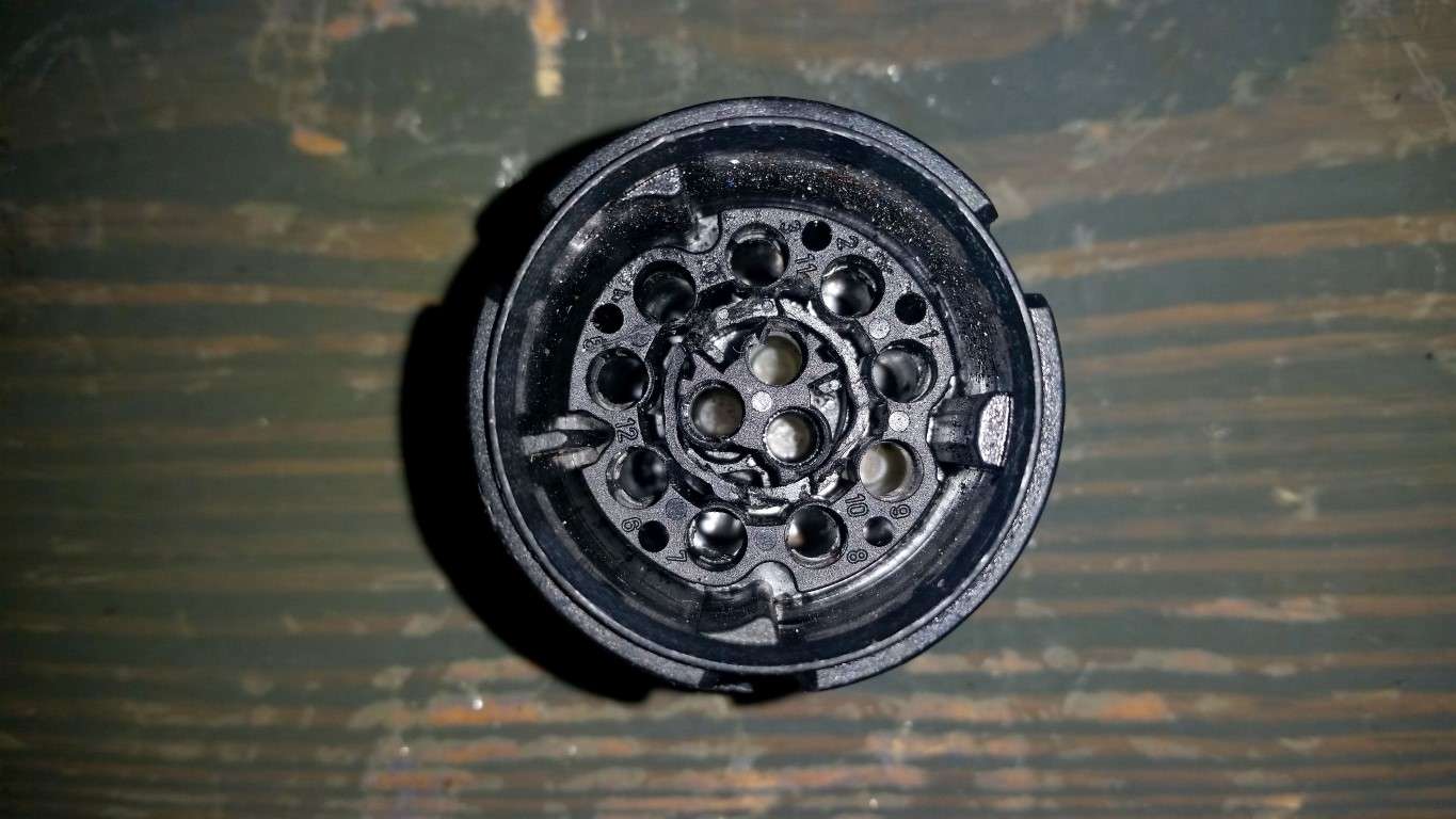
x6031 Connector
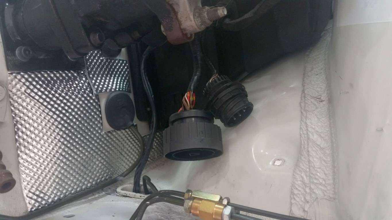
After a little thought, I came up with a very simple solution. The x69 connector - which is a 23 pin connector - is populated with only 7 pins from the factory on this vehicle. That means there were 16 vacant pin positions. So, since I know how to depin these connectors, I simply removed Pins 1 through 8 from the x6031 (completely eliminating it from the harness) and placed those pins in Positions 8 through 15 in the x69! Super simple and tidy!
x6031 Depinned
x69 (on the left) with 8 Additional Pins from the x6031
No more dangling x6031!
I also went back to the pick-n-pull today. I got another chassis side x20 connector leaving the leads as long as possible so I can redo the ABS harness extension. I'm just not satisfied with the solder joints. I've got some great soldering tips from the forums and from an aircraft mechanic buddy and feel confident I can do better.
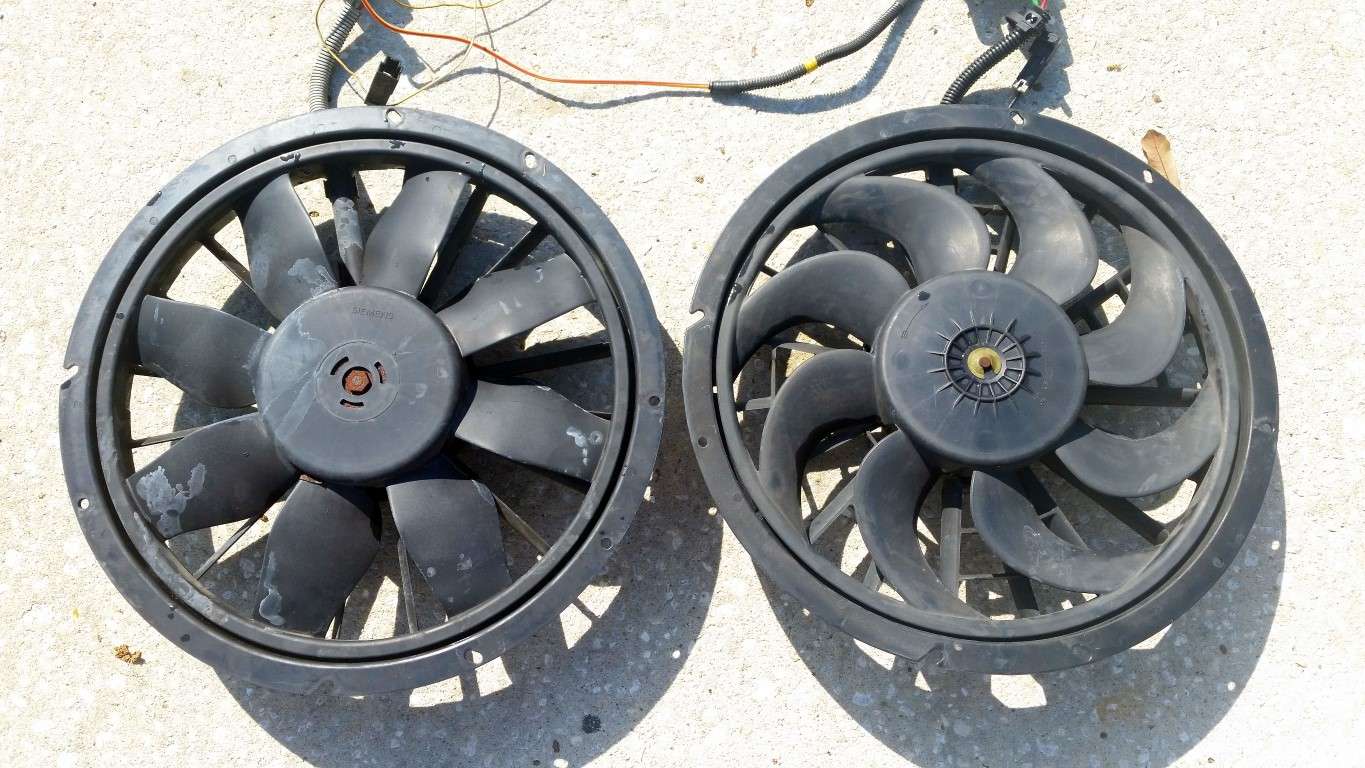
While I was there, I picked up two mid-90's Volvo 850 fans. If anyone has a simple method to test how much amperage these pull (so I can determine if they're worn out), I started another thread so please post your method here.
Tipsy
Volvo 850 Fans
JTR Mount Installed
C4 Rubber Mount
I looked at my notes and there are in fact some pins in the x6031 that I will utilize. After cutting the bracket that holds all three chassis side connectors (because of hydroboost clearance issues), the x6031 was just dangling below the hydroboost (seen blow):
x6031 Connector
After a little thought, I came up with a very simple solution. The x69 connector - which is a 23 pin connector - is populated with only 7 pins from the factory on this vehicle. That means there were 16 vacant pin positions. So, since I know how to depin these connectors, I simply removed Pins 1 through 8 from the x6031 (completely eliminating it from the harness) and placed those pins in Positions 8 through 15 in the x69! Super simple and tidy!
x6031 Depinned
x69 (on the left) with 8 Additional Pins from the x6031
No more dangling x6031!
I also went back to the pick-n-pull today. I got another chassis side x20 connector leaving the leads as long as possible so I can redo the ABS harness extension. I'm just not satisfied with the solder joints. I've got some great soldering tips from the forums and from an aircraft mechanic buddy and feel confident I can do better.
While I was there, I picked up two mid-90's Volvo 850 fans. If anyone has a simple method to test how much amperage these pull (so I can determine if they're worn out), I started another thread so please post your method here.
Tipsy
Volvo 850 Fans
Last edited by TipsyMcStagger; 11-15-2015 at 08:37 PM.
05-17-2015, 07:13 PM
#104
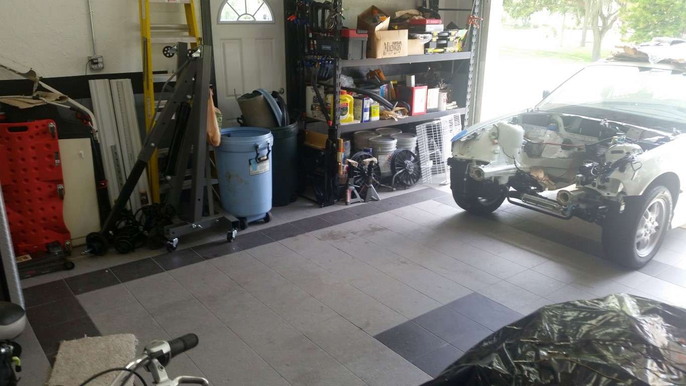
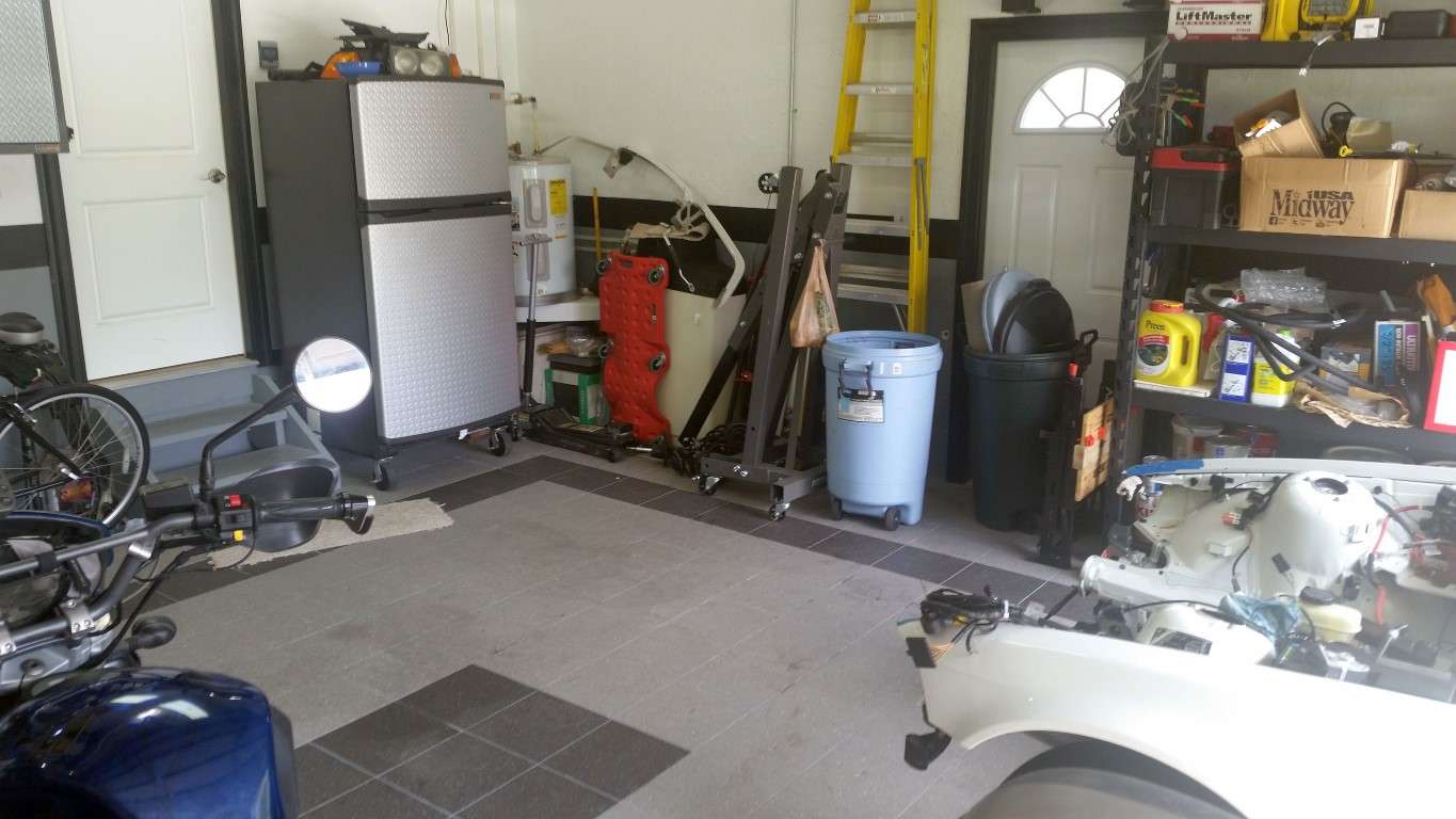
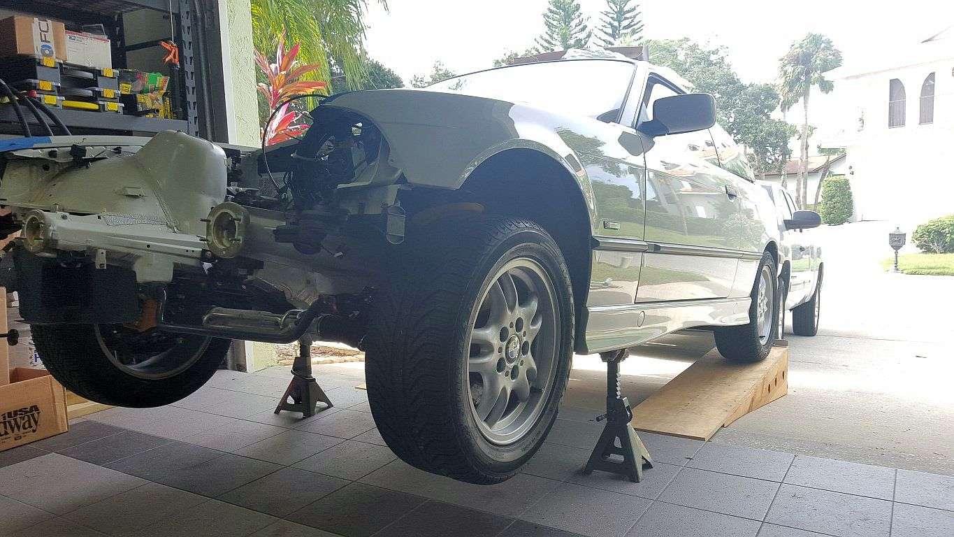
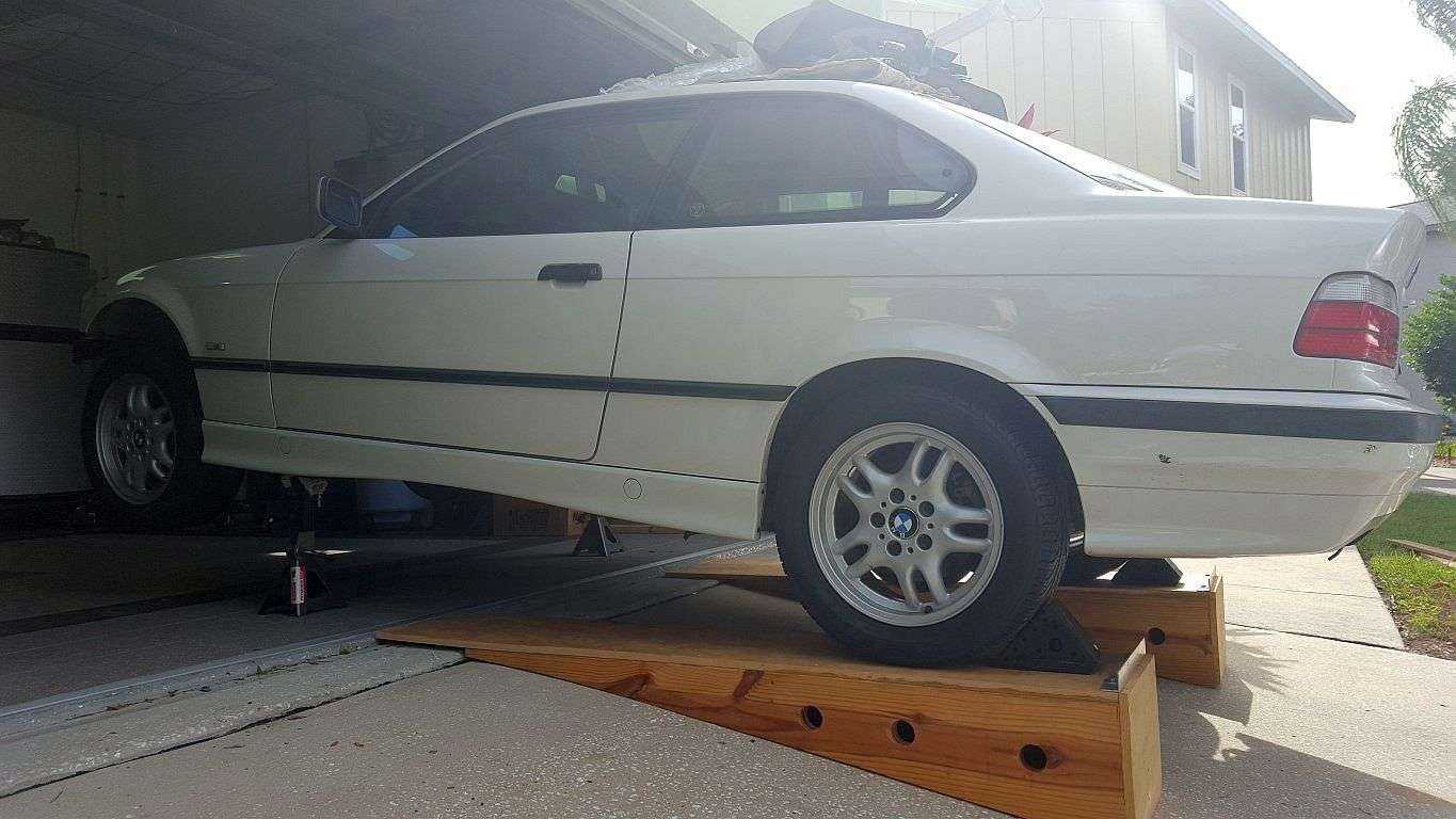
For the first time in along time, she's a roller again and off the jack stands. I got her pushed back on the ramps today and was able to get the garage cleaned up a bit. Now that I can move the car, I can get the cherry picker over to the engine. Over the next day or two, my plan is to get the engine off the stand, replace the rear main seal (I bought the cover assembly with the seal already installed), replace the pilot bearing, install the clutch and get the T56 mated to the engine. One that's accomplished, I can test fit the engine. I have to travel Friday night for two weeks, so if I can get the engine sitting in the car before I leave, that would be very cool.
Also, the EVAP saga continues. After a year or more of research and deliberation, I think I'm going to throw in the towel on EVAP. The two reasons I wanted to retain EVAP were (1) to prevent any fuel vapor/smell from accumulating in the garage and (2) just to say I made it work. But the reality is, I can't find a single write-up of anyone who has made EVAP functional in a swap with the LS2's E40 PCM. And some knowledgeable people have told me it likely won't work because the E40 is looking for some kind of CAN Bus/serial communication regarding the fuel level information (vs. just tapping into the fuel level sender circuit, like the 411 guys have done).
I also sold the BBS RG-R's I bought last year. I never really loved them and I was searching for LTW's (Style 24's) when I bought the RG-R's. LTW's are what I want. I might buy a new set if I can't find a clean used set.
Tipsy
Sticking her *** outside

Plenty of room to swing the engine with the car on the ramps
Also, the EVAP saga continues. After a year or more of research and deliberation, I think I'm going to throw in the towel on EVAP. The two reasons I wanted to retain EVAP were (1) to prevent any fuel vapor/smell from accumulating in the garage and (2) just to say I made it work. But the reality is, I can't find a single write-up of anyone who has made EVAP functional in a swap with the LS2's E40 PCM. And some knowledgeable people have told me it likely won't work because the E40 is looking for some kind of CAN Bus/serial communication regarding the fuel level information (vs. just tapping into the fuel level sender circuit, like the 411 guys have done).
I also sold the BBS RG-R's I bought last year. I never really loved them and I was searching for LTW's (Style 24's) when I bought the RG-R's. LTW's are what I want. I might buy a new set if I can't find a clean used set.
Tipsy
Sticking her *** outside
Plenty of room to swing the engine with the car on the ramps
Last edited by TipsyMcStagger; 11-15-2015 at 07:50 PM.

 05-19-2015, 09:50 AM
#107
Thanks!
I've been working on converting the stock GTO harness to standalone. It really is a lot easier once you get into it than one would think. I got a good tip from another member that I thought I'd share. If you're going to remove your rear O2 sensors you'll probably find that your remaining front O2 harness wires will need to be extended to reach the sensors in the car. Of course, you can splice and extend the wires or you can buy extension harnesses.
But a simple (and free) solution is to simply remove the front sensor wires from the harness, permanently. And then repin the rear sensor harness wires into the front senor pin positions on the PCM connector. Voila! Instantly longer wires. Of course, the color coding will be off, so keep good notes. Also, the front and rear sensors have different connectors (at least on my 2006 GTO harness) so obviously the sensors they use are different part numbers. But I did some checking and you can run rear sensors in the front sensor position with no ill effect. Or, if you want to do a little extra work, the pins in both the front and rear sensor connectors are the same. So you can just depin the individual senor connectors and swap them around. Then you can buy front sensors and plug them right in.
Hope this helps someone. I thought it was a cool tip.
Tipsy
Last edited by TipsyMcStagger; 05-19-2015 at 10:28 AM.
05-19-2015, 09:44 PM
#108
A little more progress. Valve covers are on and the engine is off the stand for the first time since I brought it home. I replaced the pilot bearing, the rear main cover and installed the flywheel. For the pilot bearing, I've read of people using everything from grease to white bread (yes, white bread) to attempt to force the pilot bearing out of the crank. I decided to take a more straight forward approach. I went to AutoZone and rented an OEM 27128 Blind Bearing Puller and an OEM 27119 Bearing Installation Tool. With these two tools, the old bearing was out and the new one was in about three minutes. That pilot bearing is in there! I was nearly dragging the engine across the floor using the slide hammer on the bearing puller. I can't imagine trying to force it out using white bread! Here's the best part; AutoZone tool rental is free. Nada! You pay upfront for the tool and as long as you bring it back within 90 days, you get a full refund. Tool rental costs less than a loaf of white bread :stickoutt
I bought the complete rear cover with the rear seal already installed (12639250). Installation was pretty straight forward. I debated whether I should drop the pan a bit but in the end, I simply removed the two oil pan bolts that attach to the rear cover. I dabbed a bit more black RTV in the corners too. The new rear cover comes with bolts and a gasket. I noticed the bolts were larger than the original cover (10mm vs 13mm, I think).
I also installed the flywheel with a set of ARP bolts. I've only got a couple of days left before I have to hit the road and tomorrow is a boat day (it's a rough life in FL), so I doubt I'll get the engine in the car before I leave. But I'll get the clutch installed and the T56 mated.
Engine soon to be mated to T56

You need this tool...

And this tool...

...To make removing and installing one of these a breeze

You can see the old bearing on the end of the puller

Old rear cover removed

New rear cover installed

I bought the complete rear cover with the rear seal already installed (12639250). Installation was pretty straight forward. I debated whether I should drop the pan a bit but in the end, I simply removed the two oil pan bolts that attach to the rear cover. I dabbed a bit more black RTV in the corners too. The new rear cover comes with bolts and a gasket. I noticed the bolts were larger than the original cover (10mm vs 13mm, I think).
I also installed the flywheel with a set of ARP bolts. I've only got a couple of days left before I have to hit the road and tomorrow is a boat day (it's a rough life in FL), so I doubt I'll get the engine in the car before I leave. But I'll get the clutch installed and the T56 mated.
Engine soon to be mated to T56
You need this tool...
And this tool...
...To make removing and installing one of these a breeze
You can see the old bearing on the end of the puller
Old rear cover removed
New rear cover installed
Last edited by TipsyMcStagger; 11-15-2015 at 06:22 PM.
06-07-2015, 10:22 AM
#110
Got the GTO harness prepped for stand-alone. There's not much that needs to be removed. I removed the wires for skip-shift, EVAP purge, horn and rear O2's. I actually left the rear O2 wires in the harness and repinned them as fronts (from C3 to C2) and I also swapped the end connectors. The factory rear O2's use flat four-pin connectors and the fronts use gray square four-pin connectors. This wasn't necessary because rear O2 sensors could have been used in the front. But doing it this way, you'll never have to remember to buy rear O2's as replacements.
I also made my own "Connector View" diagrams combining the original Sensor 1 and Sensor 2 All-Data diagrams to correctly reflect what's in the harness. I even corrected the Pin A wire color on Bank 2. It was wrong in All-Data.
Tipsy
Wires Removed

Bank 1 & Bank 2 Connector "end views" with corrects wire colors


I also made my own "Connector View" diagrams combining the original Sensor 1 and Sensor 2 All-Data diagrams to correctly reflect what's in the harness. I even corrected the Pin A wire color on Bank 2. It was wrong in All-Data.
Tipsy
Wires Removed
Bank 1 & Bank 2 Connector "end views" with corrects wire colors
Last edited by TipsyMcStagger; 11-15-2015 at 07:53 PM.
06-08-2015, 05:22 PM
#111
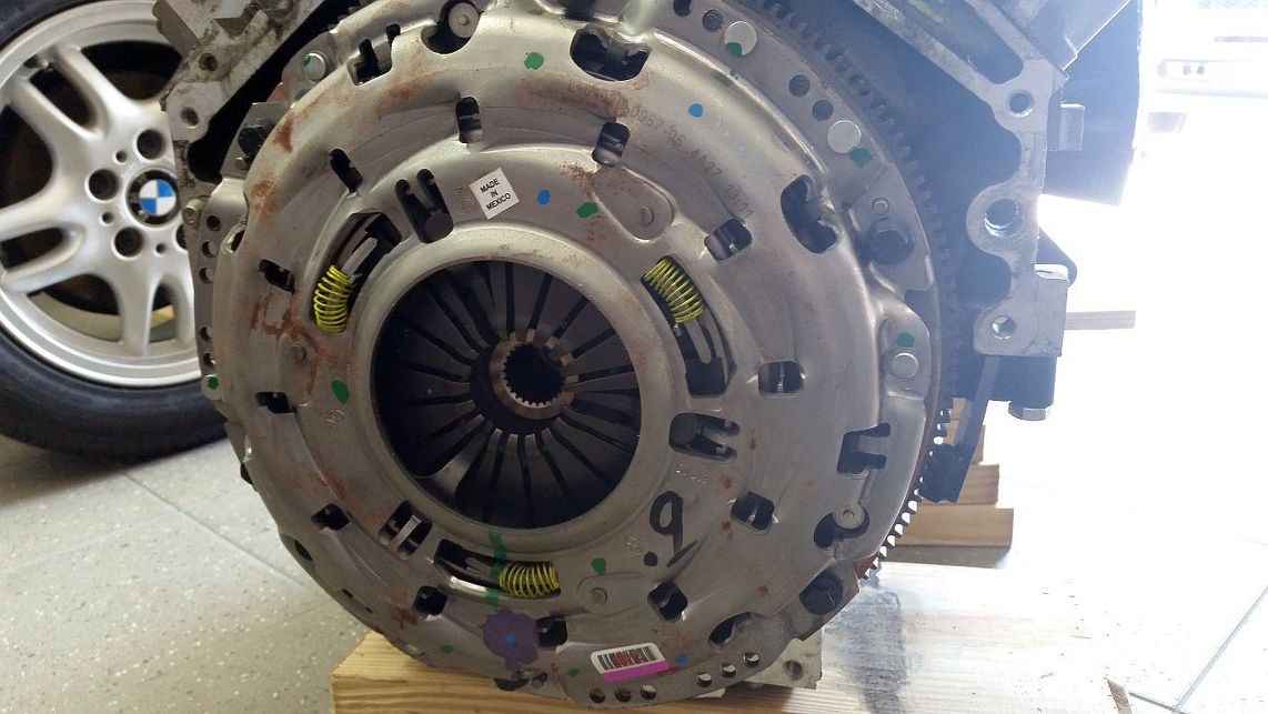
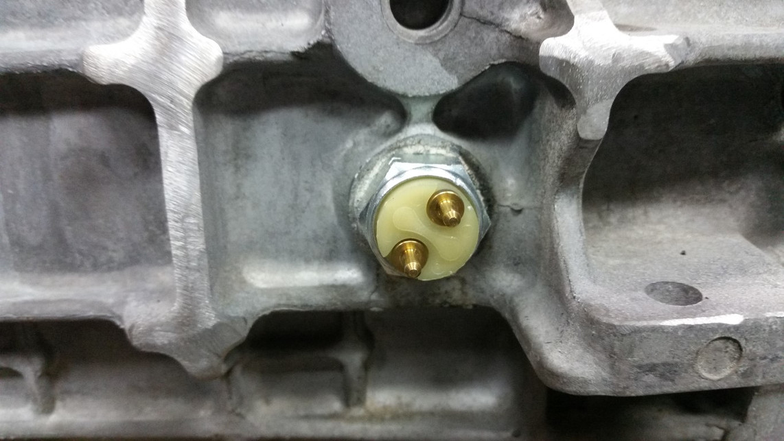
Got the clutch torqued on and installed the slave. I also installed the F-Body shifter cup and a . I've had this thing sitting on the shelf for a year and just now realized that the pigtail is male as is the GTO's harness. I'll have to repin one or the other.
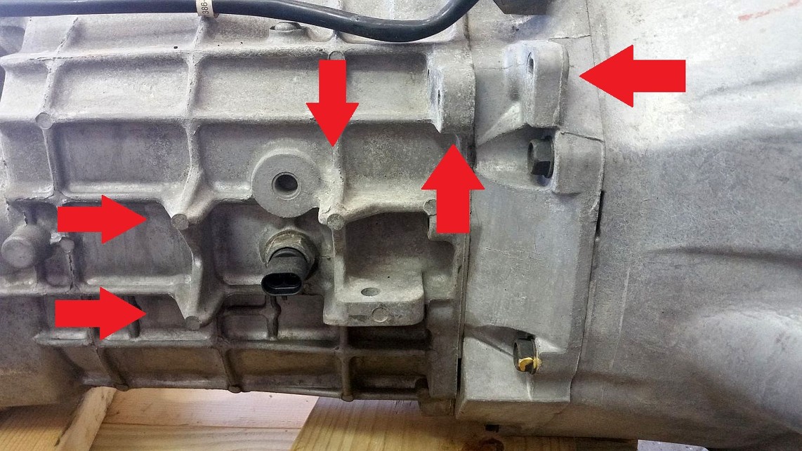
I worked on shaving a few areas on the T56 based on information others have posted in their LSx swap threads. The arrows show the material that was removed.
Tipsy
LS7 Clutch
Slave
F-Body Shifter Cup
SW-5857 Back-up Light Switch
Before
After>
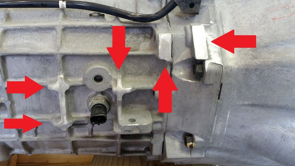
After
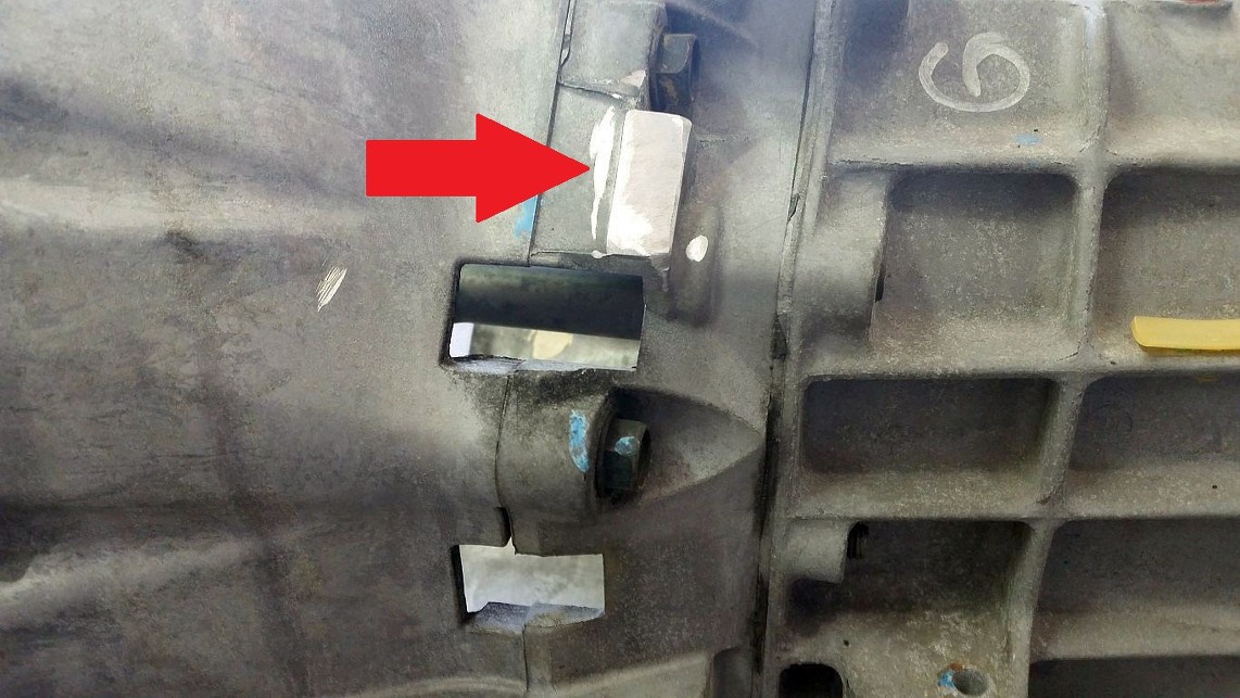
I worked on shaving a few areas on the T56 based on information others have posted in their LSx swap threads. The arrows show the material that was removed.
Tipsy
LS7 Clutch
Slave
F-Body Shifter Cup
SW-5857 Back-up Light Switch
Before
After>
After
06-09-2015, 05:36 PM
#112
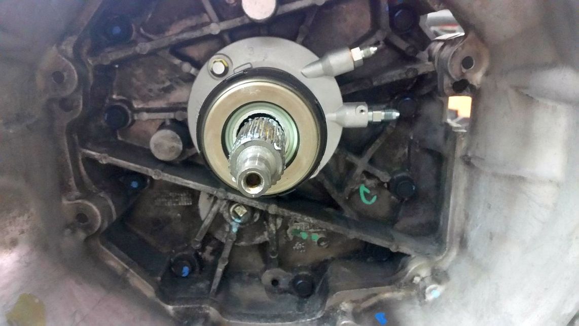
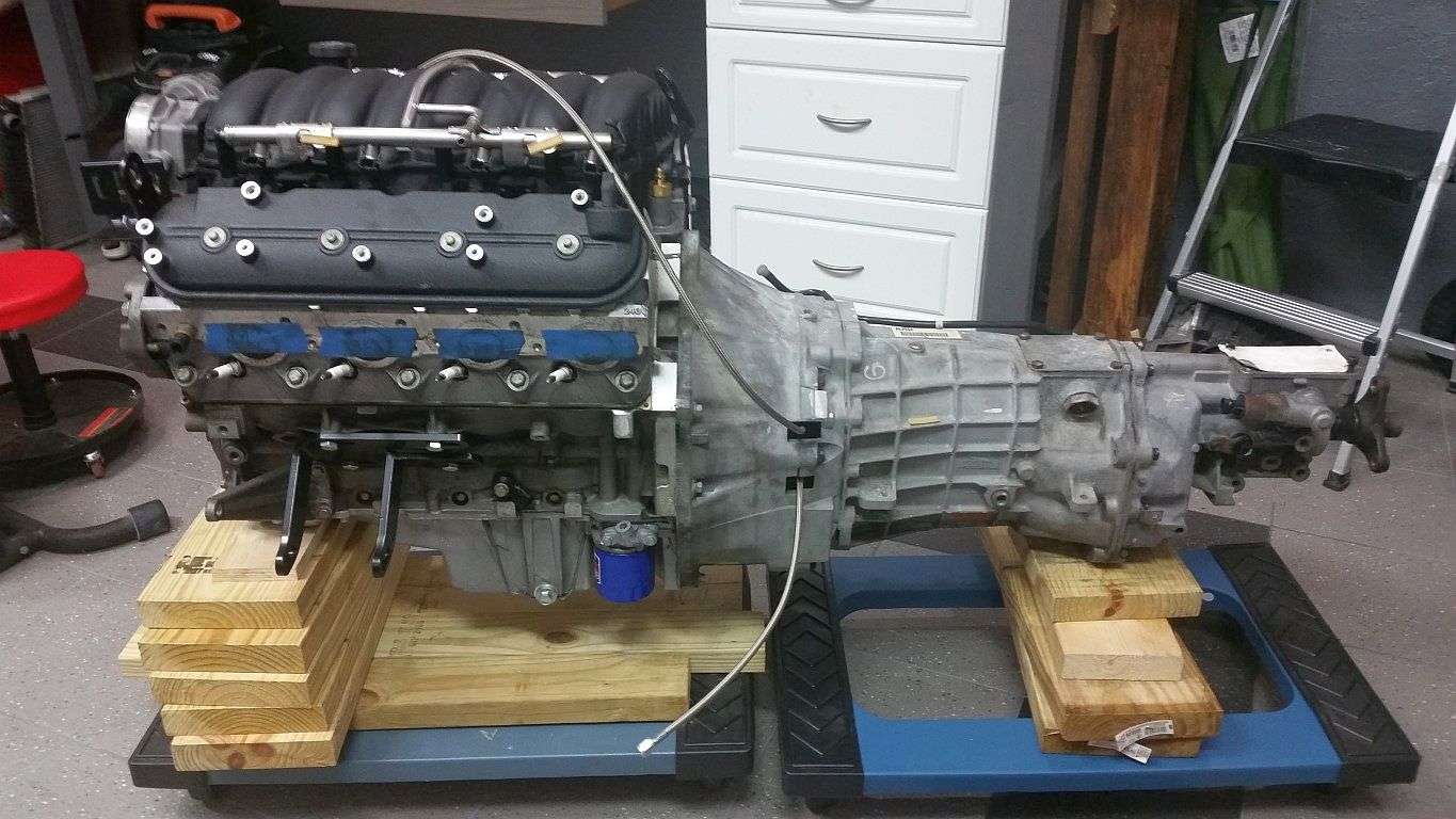
I got the trans on the engine today, which ended up taking way more time than anticipated. The first challenge was simply getting the input shaft to properly engage the pilot bearing. I was using guide pins I made by cutting the heads off a couple of long bolts to help locate the trans but it was still a bear, especially in a 95+ degree garage. Once the input shaft found the pilot bearing, only one side of the trans would sit flush to the block. When I originally separated the trans from the engine, one of the dowel pins stayed in the engine and one stayed in the bellhousing. I think the pin that stayed in the bellhousing, for whatever reason, didn't want to engage the opening in the block. I recall reading a post about a cracked block that resulted from trying to draw the trans to the block by pulling it in while tightening the bellhousing bolts, so I was in no hurry to force anything into place.
After much wresting, deliberation and frustration, I was convinced there was nothing but an ever so slightly misaligned dowel pin preventing the bellhousing from mating fully to the block. So, I VERY gingerly tightened all of the bellhousing bolts and ultimately, it pulled in and seated flush. That was a nail biter. I did NOT want to end up with a cracked block!
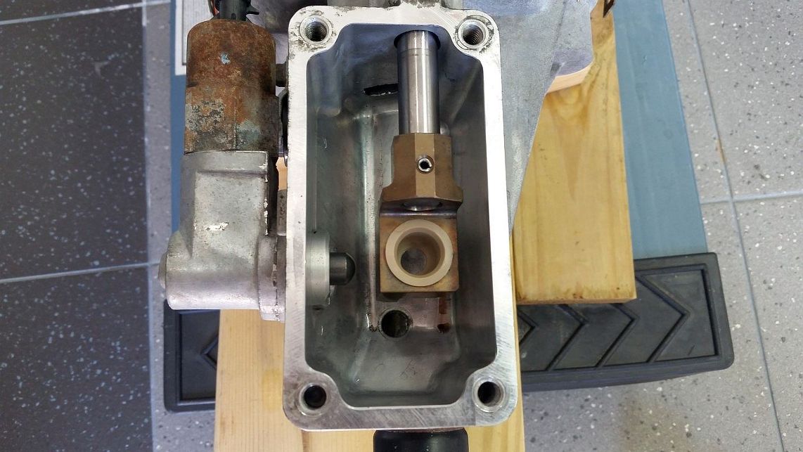
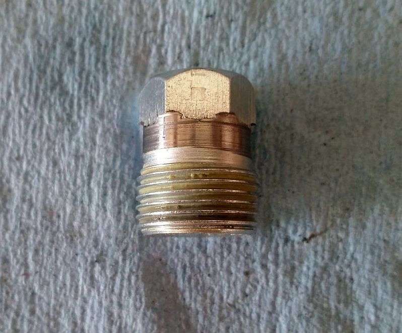
I removed the skip shift solenoid and at first plugged the opening with an M20x1.5 oil drain plug with the flange removed. With the flange on, the plug will only engage a thread or two. But with the flange machined down, I didn't like that the plug really didn't tighten.
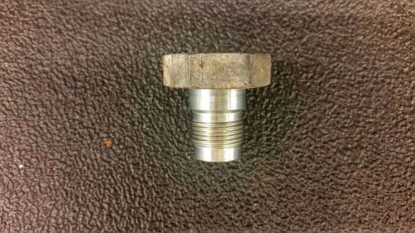
So, on to plan B - Skip Shift Solenoid surgery. I used a technique I'd read about here and had a local fab shop cut the solenoid in half, remove the guts and dab a bit of weld on the plunger inside to seal it off. Worked great! This is the way to go if you want to fully eliminate the bulky solenoid.
Tipsy
Start of the Day

End of the day

M20x1.5 Drain Plug with Flange Removed
Modified Skip Shift Solenoid

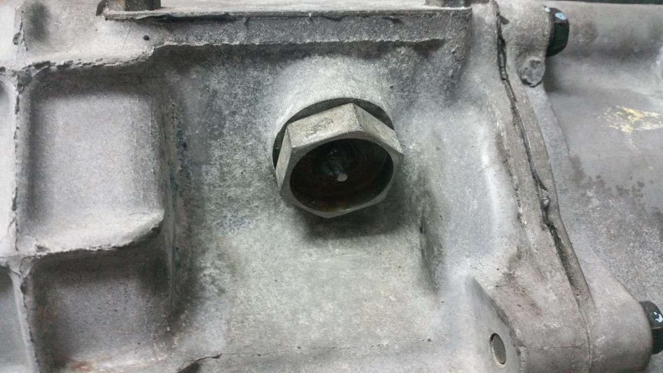
Plug Installed
After much wresting, deliberation and frustration, I was convinced there was nothing but an ever so slightly misaligned dowel pin preventing the bellhousing from mating fully to the block. So, I VERY gingerly tightened all of the bellhousing bolts and ultimately, it pulled in and seated flush. That was a nail biter. I did NOT want to end up with a cracked block!
I removed the skip shift solenoid and at first plugged the opening with an M20x1.5 oil drain plug with the flange removed. With the flange on, the plug will only engage a thread or two. But with the flange machined down, I didn't like that the plug really didn't tighten.
So, on to plan B - Skip Shift Solenoid surgery. I used a technique I'd read about here and had a local fab shop cut the solenoid in half, remove the guts and dab a bit of weld on the plunger inside to seal it off. Worked great! This is the way to go if you want to fully eliminate the bulky solenoid.
Tipsy
Start of the Day
End of the day
M20x1.5 Drain Plug with Flange Removed
Modified Skip Shift Solenoid
Plug Installed
Last edited by TipsyMcStagger; 11-15-2015 at 07:49 PM.
06-09-2015, 09:22 PM
#113
mating those two big bastards is no joke when it's a one man operation. I just did that this weekend and invented cursewords I didn't know I was capable of. Part of it had to do with the fresh coat of paint on the dowels from when I painted the block - I'm sure it added a few thou of thickness to the OD. Corrosion on the dowels has the same effect.
Kudos to getting it done with no issues! Looking forward to more of your progress.
Kudos to getting it done with no issues! Looking forward to more of your progress.

 06-13-2015, 10:20 PM
#116
08-09-2015, 11:02 AM
#117
Not a lot to report. I haven't been in FL much and the last time I was here for 12 days, it rained heavily every day...no joke. Lots of flooding around Tampa. That, the heat and my traveling have slowed progress.
When we removed the stock engine, we folded the hood back to the "service" position which resulted in a cracked windshield. I've been wanting to swap the tan dash for a black dash, so I figured I'd make things easy for myself and do it while the windshield was removed. I had the glass guys come on Friday to remove the cracked windshield, I swapped the dash on Saturday and they came back Monday to install the new glass.
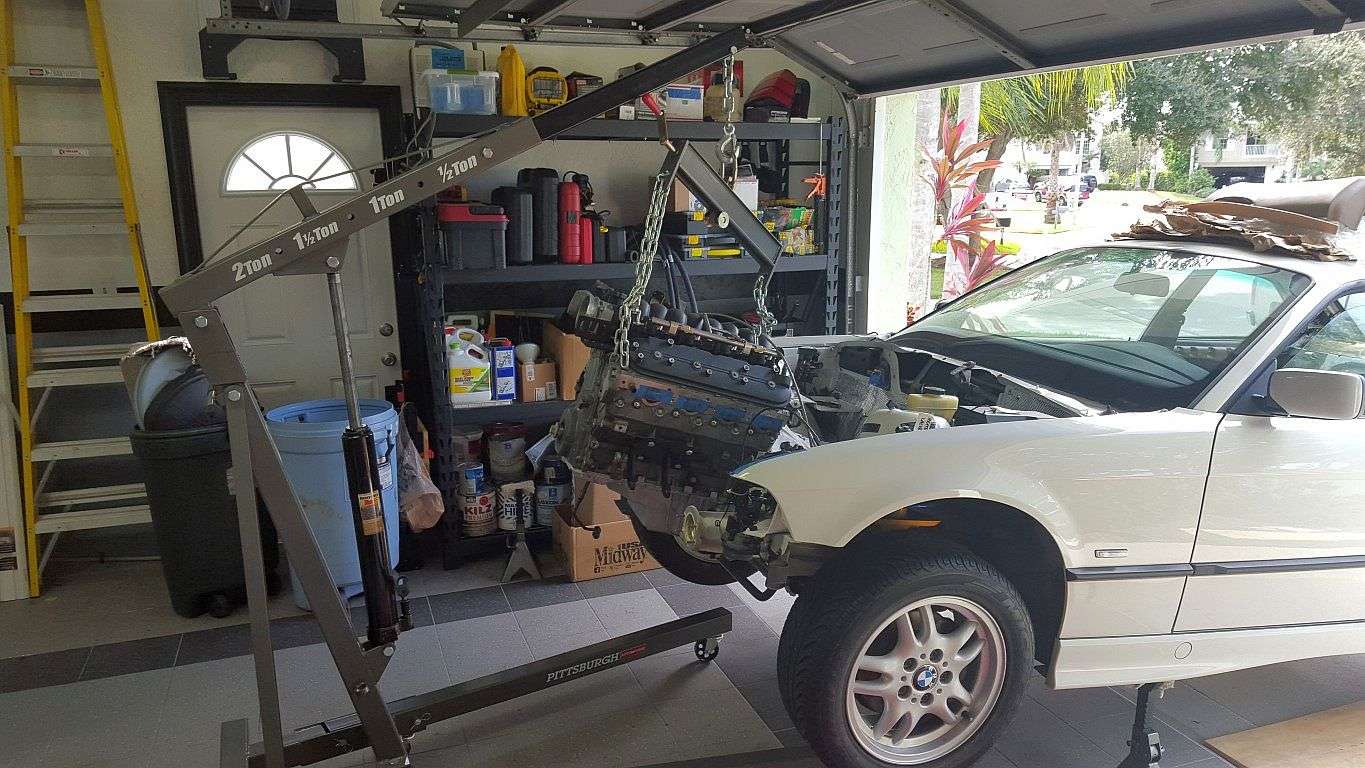
I'm hitting the road again in the morning but the engine is sitting next to the car ready for a test fit. I realized I never removed the stock shifter bushing bracket thingy that's mounted in the tunnel just aft of the shifter opening, so this morning I did so.
Now, when I get back, I'm 100% ready to swing the engine in for a test fit.
Tipsy
Dash Removed

"New" Black Dash

Stock Shifter Bushing Thingy

Engine Patiently Waiting
When we removed the stock engine, we folded the hood back to the "service" position which resulted in a cracked windshield. I've been wanting to swap the tan dash for a black dash, so I figured I'd make things easy for myself and do it while the windshield was removed. I had the glass guys come on Friday to remove the cracked windshield, I swapped the dash on Saturday and they came back Monday to install the new glass.
I'm hitting the road again in the morning but the engine is sitting next to the car ready for a test fit. I realized I never removed the stock shifter bushing bracket thingy that's mounted in the tunnel just aft of the shifter opening, so this morning I did so.
Now, when I get back, I'm 100% ready to swing the engine in for a test fit.
Tipsy
Dash Removed
"New" Black Dash
Stock Shifter Bushing Thingy
Engine Patiently Waiting
Last edited by TipsyMcStagger; 11-15-2015 at 05:55 PM.
11-15-2015, 05:40 PM
#118
As always, sorry for the crappy cell phone pics. I have no idea how to keep the bright sun from washing things out.
Anyway, some progress. The engine is in! Okay, it's just a test fit but it's gratifying nonetheless. Truth be told, I'd had some days in the past several weeks where I could have accomplished this, but I was intimidated by trying to swing the engine-in without a second set of hands. Today, I said the hell with it and gave it a go. It really wasn't that bad. The hardest part was maneuvering a jack under the transmission because it was so close to the edge of the garage slab. The hoist legs and the jack-stand prevented me from bringing the jack in from another angle.
There are only two small spots I can see where I'll have to massage the tunnel a bit. I'll need to get the steering column back in so I can test fit the headers and the steering shaft.
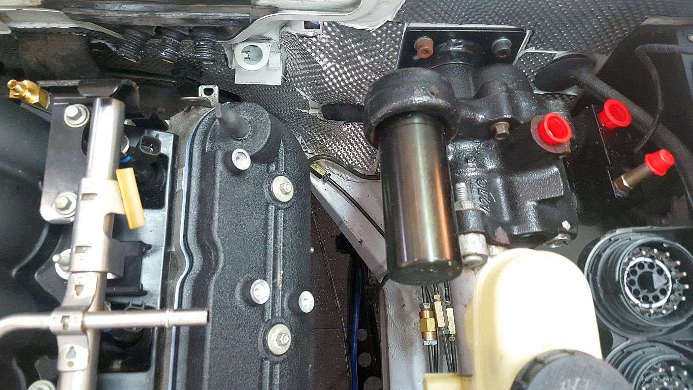
Look at all of the room between the hydroboost and the valve cover! Very happy with the decision to go with the hydroboost vs. a smaller Merc booster.
Tipsy
On the Ramps
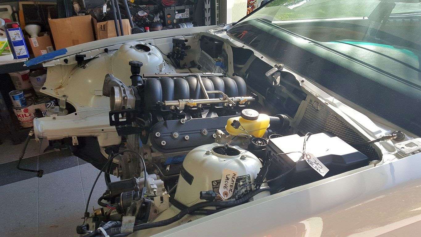
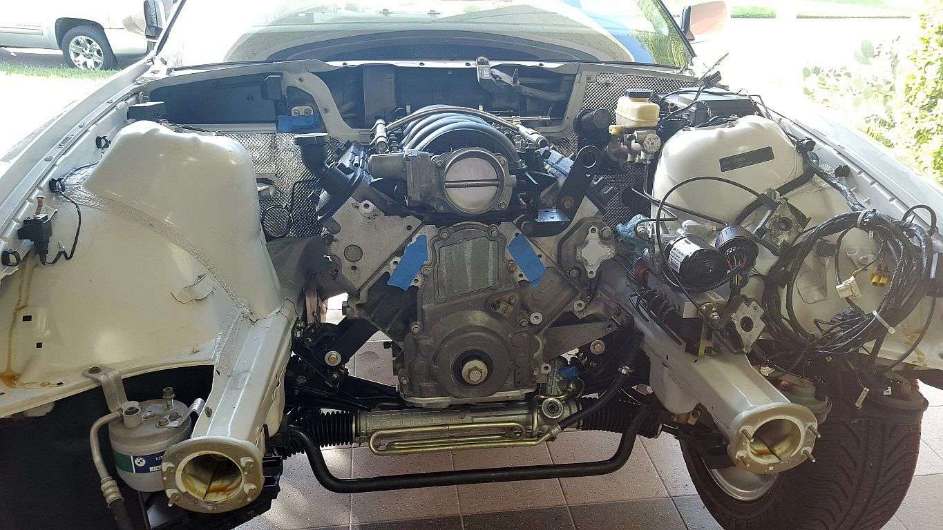
Hydroboost Clearance
Anyway, some progress. The engine is in! Okay, it's just a test fit but it's gratifying nonetheless. Truth be told, I'd had some days in the past several weeks where I could have accomplished this, but I was intimidated by trying to swing the engine-in without a second set of hands. Today, I said the hell with it and gave it a go. It really wasn't that bad. The hardest part was maneuvering a jack under the transmission because it was so close to the edge of the garage slab. The hoist legs and the jack-stand prevented me from bringing the jack in from another angle.
There are only two small spots I can see where I'll have to massage the tunnel a bit. I'll need to get the steering column back in so I can test fit the headers and the steering shaft.
Look at all of the room between the hydroboost and the valve cover! Very happy with the decision to go with the hydroboost vs. a smaller Merc booster.
Tipsy
On the Ramps
Hydroboost Clearance
