


PNP wire question
I've hooked this wire up in the past, but was wondering if its really necessary. It's the org/blk #34 out of the PCM, supposed to go to ground in park and neutral, but what I'm working on now, it's not possible to do, as there is no ground on the switch, it would appear that if hooked up to the neutral safety swiych, it would send 12 volts to the PCM when you cranked it. Any suggestions? Thanks, Eric
Joined: Sep 2004
Posts: 3,148
Likes: 12
From: Downers Grove, IL
If you don`t have a convenient way to hook the P/N switch up you can do without it. In HPTuners there is the option for the P/N switch and you can set it to enable or in this case disable. I know a few people have done without it and they didn`t really report any problems. One person didn`t have the P/N switch or a VSS and for the most part it was fine, said that every once in a while it felt like it was going to die out when coming to a stop, but that it never did.
OK, thanks, I'll see if I can get that programmed out when I send the PCM out. And I ran a TPI without a VSS and it did what you were saying, would act like it wanted to die when you came to a fast stop, only sometimes it did. Thanks again, Eric
TECH Resident
Joined: Nov 2007
Posts: 816
Likes: 0
From: Texas
OK I have the same issue. MY 65 cutlass park neutral switch is positive voltage and it disrupts the purple starter wire to operate. I grounded my pcm pnp wire and have started the car with and without this wire connected. I was going to install a micro switch on the pnp and break switch because it too operates the opposite of the pcm. But the car starts and runs the same without either of them connected. I have had the break switch connected to positive 12 volts and disconnected. I had the pcm tuned at waitformeperformance. I thought Jesse told me that it was going to be left in. If it is still in the program should the car start if it is not grounded?
S10Wildside To perform a crank relearn the PCM needs to know the vehicle is in park. This is the only signal to the PCM to indicate park. You could manually ground the wire if/when crank relearn is required.
Trending Topics
TECH Resident
Joined: Nov 2007
Posts: 816
Likes: 0
From: Texas
I was hoping the PNP is the safety switch and would prevent the car from starting if not grounded. If that had been the case I could have harded wired my purple starter wire and ran my factory park switch to ground and saved having to purchase and figure out how to mount another switch.
LS1 Tech Stories
The Best V8 Stories One Small Block at Time

Topdon ONE vs. Artidiag 800 BT2: Which is the Diagnostic Tablet For You?
Pouria Savadkouei
Gas Monkey Built a 6-Wheel Ferrari Testarossa With a Corvette LT4 Engine
Verdad Gallardo
7 Most Reliable High-Performance Engines GM Has Ever Built
Verdad Gallardo
Amazing '71 Camaro Restomod Is Modern Muscle Car Under the Skin
Verdad Gallardo
6 Common C5 Corvette Failures and What's Involved In Repairing Them
Pouria Savadkouei
Retro Modern Bandit Pontiac Trans AM Comes With Burt Reynolds' Autograph
Verdad Gallardo
Top 10 Greatest Cadillac V Series Performance Models Ever, Ranked
Pouria Savadkouei
Top 10 Most Powerful Chevy Trucks Ever Made!

Hennessey's New Supercharged Silverado ZR2 Has 700 HP
Verdad GallardoTECH Resident
Joined: Nov 2007
Posts: 816
Likes: 0
From: Texas
According to Jesse at wait4me the pnp is not a safety switch at all and is needed because the pcm reads different tables depending on the switch being in park or not. The rev limits etc.. are different in these tables in the pcm. I think I'll wire mine as planned using micro limit switches.
now that i think of it, i just put the PNP wire to ground and see no difference in operation. No codes the car runs fine and i have no issues with rev limits or idle speed. jesse at wait4me tuned my pcm aswell.
Joined: Sep 2004
Posts: 3,148
Likes: 12
From: Downers Grove, IL
Cherryelky:
You already have a P/N switch in your car, it just needs to be hooked up. When you pulled the old computer out of the pass kick panel the wiring harness went up to a connector that connected to the dash harness. Pin N should be an orange with black stripe wire....that is your P/N switch, that wire is grounded in park and neutral.
rockytopper:
Yes, the PCM does read different tables if it is in P/N or in gear, I attached a few screenshots. On the TCC switch, you should have that hooked up. That allows the transmission to lock the torque convertor in overdrive, if it is not hooked up the torque convertor will not lock up so it will slip and create heat which will shorten the life of the transmission. Running the TC unlocked in OD can burn up the trans quick.
I downloaded a 5.7L F-Body tune and it appears that the option that I thought was to enable the P/N switch is really an option to disable the more complicated truck only gear selector switch(I only had a truck tune before because I don`t have anything with a f-body/vette/GTO motor/trans). There appears to be no way to tune the P/N switch out. But if you can`t run one you could also copy the idle RPM tables for when its in gear and paste them in to the P/N table.....the engine would idle higher when its out of gear, but if you go through and edit all the tables you could make it work OK without a P/N switch. Of course even after you do that it would probably not be as seamless as a factory tune with a P/N switch, but you can make it work without a P/N switch. Is it the best solution, no, but will it work, yes.
If you have a P/N switch that puts out 12V in park/neutral, you can use a relay to reverse it so that it puts out a ground sig in P/N
TECH Resident
Joined: Nov 2007
Posts: 816
Likes: 0
From: Texas
"If you have a P/N switch that puts out 12V in park/neutral, you can use a relay to reverse it so that it puts out a ground sig in P/N"
G I was thinking that my self. You wouldn't happen to have a wiring diagram for that would you? It will only see 12v at cranking startup. How does that work?
G I was thinking that my self. You wouldn't happen to have a wiring diagram for that would you? It will only see 12v at cranking startup. How does that work?
G body, my car was already converted to a regular carb and stripped of the computer when i got to it, but it does have a P/N switch in the column, its a mechanical one that stops the key from turning unless its in park or neutral.
Damn!! Well I guess I'm back to the old drawing board! I'm in the same situation as rockytopper, my switch will only see 12 volts during cranking, so reversing it with a relay won't work. I guess I'll have to mount another switch somewhere. My Nova and my '33 both have two neutral safety switches mounted on the column, it's not hard to mount the extra one if you have a GM column, but now I'm working on a Ford with a retarded looking column. It has no place for one as the switch was built into the trans. however I did manage to get one mounted to the column, but there is NO WAY I can put another one on it! BTW, Cherryelky305, I think what G-Body was talking about is the actual PNP switch mounted at the base of the column near the floor, it also controls your back-up lights. I wouldn't think they would have removed that when they removed the old computer.
Joined: Sep 2004
Posts: 3,148
Likes: 12
From: Downers Grove, IL
I don`t have a diagram to make a relay reverse the polarity, but I can write one up here.
The numbering scheme is the bosch standard used on all the automotive relays I have seen.
Terminal 30 to ground
terminal 87 is the - output
terminal 86 to ground
terminal 85 to the 12v signal in
That will give a ground output every time that you put a 12V signal in.
I think I have a way to make a single P/N switch work for the PCM and for the starter interrupt. I will post a diagram tonight if I don`t fall asleep first, if not I`ll get it up here tomorrow.
OK, I'm back from the drawing board and I think I got it! I spent several hours at work last night pondering my dilemma, was a slow night, and this is what I came up with. Actually this is what several co-workers and I came up with, at one point I think everybody in the shop was trying to figure it out (some were just trying to figure out what the hell I was doing!) At first we came up with a way to do this using a double pole relay, but I changed it to two single relays as they are easier to find, and I have alot of them lying around. Plus on the chance the one going to the starter shoots craps, I could just put the one for the PCM ground in in it's place so I could at least get home. The schematic I drew isn't real fancy, and the terminals on the relays aren't marked, but if you can read a schematic (and I'm assuming most on here trying to wire their own car can) then it should be fairly self explainatory. This should work for alot of early GM cars that have the purple wire going to the starter with the neutral safety switch in this wire. If anyone sees a reason that this won't work, let me know, but I'm going to give it a shot! Hope this helps. Also put a pic of the car I'm working on in case anyone was curious.
Joined: Sep 2004
Posts: 3,148
Likes: 12
From: Downers Grove, IL
That will work. Its almost exactly what I was going to suggest. I drew up a diagram today, but I only used 1 relay. Your schematic is better, because it isolates the PNP wire from the PCM where as mine does not, but it should work either way.
TECH Resident
Joined: Nov 2007
Posts: 816
Likes: 0
From: Texas
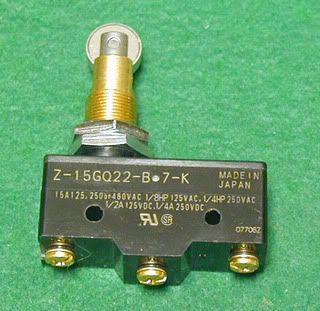
G thanks for the wiring guru info. I chose to wuss out and went with micro switches instead. The brake switch in my case was a direct replacement fit with what it had installed from the factory. This switch allows for both constant 12v and 12v with brake applied. I use the same switch for PNP. I fabed a bracket on the side of the A4 trans and mounted it next to the shifter fork. I can only read park not neutral but was told that is all that is necessary.
12 bucks for 4 on ebay.
12 bucks for 4 on ebay.
Last edited by rockytopper; Mar 10, 2008 at 04:24 PM.

Yes, thread from the dead, but at least I'm using the search button. LOL
I thought I had the diagram from post 17 figured out, but what I'm thinking now, is that this might NOT work.....due to the fact that the "key on ign 12V" would NOT be active when you turn the key, right? I thought that during a start, all ACC lines go dead? Only true, full-time HOT wires stayed active? So wouldn't the diagram in post 17 not allow the car to start? I think it would work fine for the PNP from the PCM, but once you crank it over, the "key on ign 12v" would die, causing the relay in the starter circuit to not lock in.
Thoughts?