
5.3 Turbo Thirdgen winter project


 I'm sure that can be arranged. I felt like I kept my car too quite last time I was down there, seemed like some people were a bit suprised later in the night.
  01-29-2009, 08:00 AM
#84
TECH Regular
Thread Starter
iTrader: (15)

Join Date: Jun 2004
Location: Shawnee KS
Posts: 498
Likes: 0
Received 0 Likes
on
0 Posts

Thought I would make a little update. Log manifold is wrapped, and so is the DP. The engine is back on the stand while I do some rust repair in the engine bay, and install the transbreak in the tranny. Hopefully I can get some pics of the whole kit on the engine while it is on the stand. While the engine is on the stand, I have started working on the harness again. I have been in the process of repinning the 03 truck harness to match a 02 Fbody, as I read my DBW computer would not beable to be flashed to control a DBC set up, so I ordered a 02 camaro PCM. I still can not decide where I want the computer to be located, with out extending wires I can put it over the fender next to the brake booster, or I can extend some wires and place it kind of in the stock location, and route the wires through the firewall behind the motor to where hardly anything would be visable.
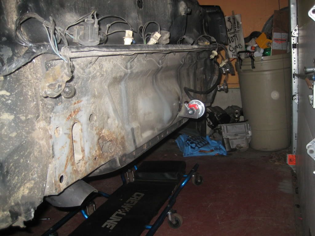
Got the heater lines done, ran hardline from the fire wall, below the heater box, and then lay on the frame rail, and finally turn to point at the waterpump where rubber hose will be used to connect them, similar to a 4th gen set up.
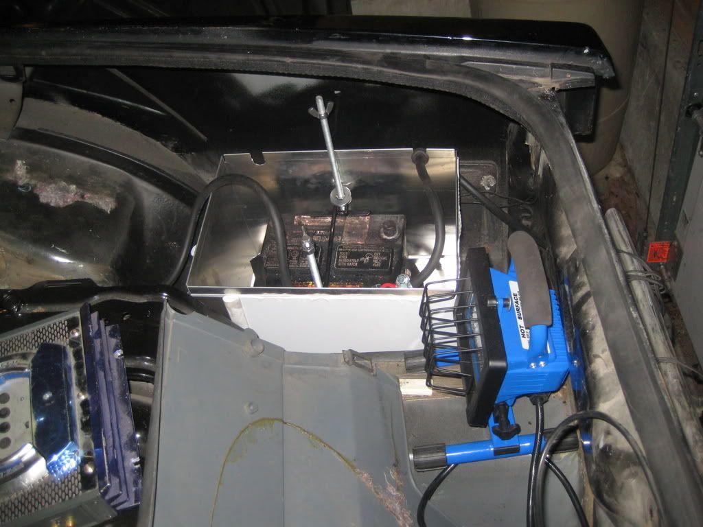
Battery relocation is about finished up, I just need to route and secure the wires a little better and get a hole in the bumper where the plate is to install a push rod that will be installed at the track only.
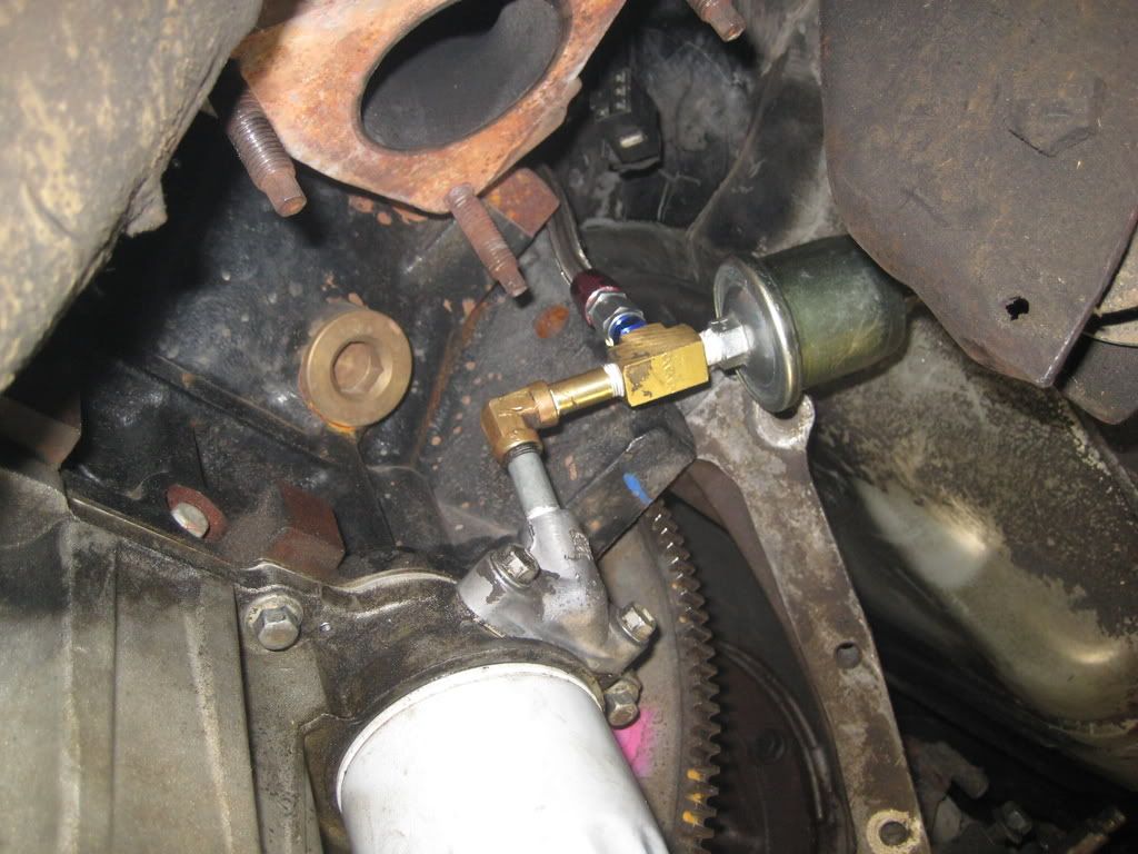
Oil feed is all set up now, along with the gauge oil pressure sending unit.
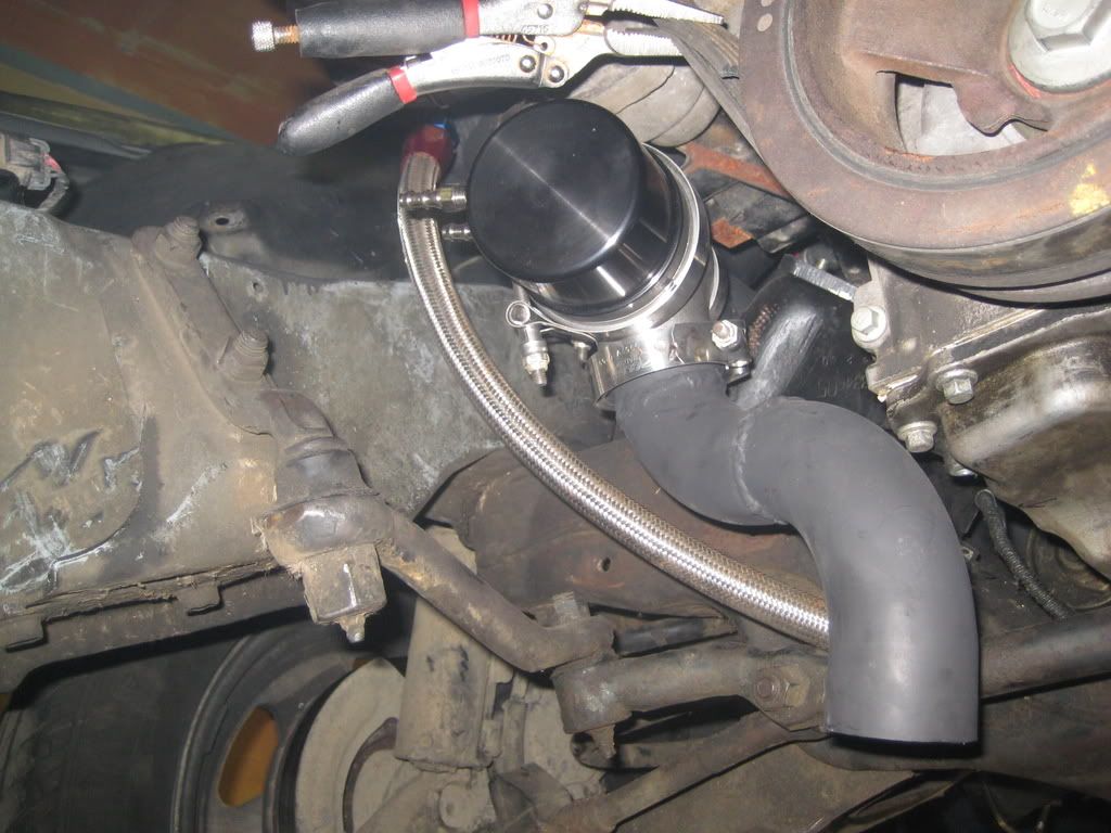
Where the wastegate is located and the dump tube for it routed around the steering components.
Got the heater lines done, ran hardline from the fire wall, below the heater box, and then lay on the frame rail, and finally turn to point at the waterpump where rubber hose will be used to connect them, similar to a 4th gen set up.
Battery relocation is about finished up, I just need to route and secure the wires a little better and get a hole in the bumper where the plate is to install a push rod that will be installed at the track only.
Oil feed is all set up now, along with the gauge oil pressure sending unit.
Where the wastegate is located and the dump tube for it routed around the steering components.
 02-04-2009, 09:08 AM
#87
TECH Regular
Thread Starter
iTrader: (15)
Join Date: Jun 2004
Location: Shawnee KS
Posts: 498
Likes: 0
Received 0 Likes
on
0 Posts
Thought I would post an update, car was torn back down to make a few changes, and to install the Trinity trans break and manual control conversion.
One of the steps has you remove the second teflon seal on the center support, and then a seal on the apply piston in the direct clutch. This is my first time into a tranny so I bought a book and a video to help with tearing it down. Found the forward clutch pack was burned up, there was no friction material left, and the direct clutch was also burned up, so I did a complete rebuild.
I think the book/video is from ATSG, well I was following along to the video for the main component reassembly, and the instructor did not go over the 1-2 band install, so after the pump was lined up, I looked over in the parts box and saw the 1-2 band, 3hrs later I had it in and the pump back in place, lining up the forward clutch was a chore, and took about 2 hrs to get it to finally fall in all the way.
Front pump is back on and the VB is in place, just needs to be bolted down and some internal wiring done for the break, shift solenoid elimination, and TCC wired up. Hopefully tonight I can finish that up, install the new Edge 3500 lock up converter and set the motor/trans back into the car for a driveshaft measurement.
I have completed the harness repin, mounted the ECU, and started to hook up the gauges/power feeds. The new black interior is all in, and is so much nicer then the stained grey that has been in there sense I have owned the car.
I plan on getting the car running this weekend, just need to install the new driveshaft, harness, cooling system, turbo kit, tranny cooler lines/cooler and probably make 10 more runs to part stores to do it all
02-04-2009, 11:23 AM
#88
TECH Enthusiast
iTrader: (5)
Join Date: Aug 2008
Location: nh
Posts: 656
Likes: 0
Received 0 Likes
on
0 Posts
Just make sure you put the boost valve in the right way in the front pump! We found out the hard way. The trans would last about 100 miles, shift like you were hit by a train, and then it would tear all of the lugs out of the case center! We figured it out on the 3rd case! DDOOOOHHHH!!!! 
02-04-2009, 03:32 PM
#90
TECH Regular
Thread Starter
iTrader: (15)
Join Date: Jun 2004
Location: Shawnee KS
Posts: 498
Likes: 0
Received 0 Likes
on
0 Posts
Just make sure you put the boost valve in the right way in the front pump! We found out the hard way. The trans would last about 100 miles, shift like you were hit by a train, and then it would tear all of the lugs out of the case center! We figured it out on the 3rd case! DDOOOOHHHH!!!!
ATSG in the video kept making note that the killer of the center lugs was the snap ring having the opening at 9 o clock and not 3 o clock, yet their book says to install with the opening at 9
02-04-2009, 08:51 PM
#91
TECH Enthusiast
iTrader: (5)
Join Date: Aug 2008
Location: nh
Posts: 656
Likes: 0
Received 0 Likes
on
0 Posts
Im a GM master tech and all of the unit repairs that we have for Th400 and 4l80's have the snap ring at the 9 oclock position. If you get the boost valve in backwards you will be running max line pressure that the pump can put out all the time and unregulated. It will be in the 400-450psi range instead of the 280 it should be. When that much pressure hits the clutch packs it will snap the lugs right off and push everything forward in the case. Nasty mess!
02-05-2009, 02:44 AM
#92
if the takeoff was from steel, you might get away with this, but it being aluminium it will break
 .
.perhaps if you make some sort of support for the sending unit, it might last a bit longer IMHO
great project, very interested in the results !
Last edited by jeejee; 02-05-2009 at 02:44 AM. Reason: typo
02-05-2009, 08:38 AM
#93
TECH Regular
Thread Starter
iTrader: (15)
Join Date: Jun 2004
Location: Shawnee KS
Posts: 498
Likes: 0
Received 0 Likes
on
0 Posts
you might want to rethink this..
if the takeoff was from steel, you might get away with this, but it being aluminium it will break.
perhaps if you make some sort of support for the sending unit, it might last a bit longer IMHO
great project, very interested in the results !
if the takeoff was from steel, you might get away with this, but it being aluminium it will break
.perhaps if you make some sort of support for the sending unit, it might last a bit longer IMHO
great project, very interested in the results !
02-05-2009, 08:41 AM
#94
TECH Enthusiast
iTrader: (5)
Join Date: Aug 2008
Location: nh
Posts: 656
Likes: 0
Received 0 Likes
on
0 Posts
I was thinking the same thing. The vibration from the motor alone will make that thing snap off in due time. I was thinking you could run a feed from there and have the sender op on the back of the intake area or visea versa. or just use a brass tee that was male/female/female. Check your local hardware store. 
02-08-2009, 03:51 AM
#96
TECH Regular
Thread Starter
iTrader: (15)
Join Date: Jun 2004
Location: Shawnee KS
Posts: 498
Likes: 0
Received 0 Likes
on
0 Posts
Well I got the car running that is for sure. No wideband currently as the sensor crapped out on the nitrous set up and the replacement will not be in until monday.
I rebuild the 4l80 myself and had sometrouble with left over parts, and found out I did not have 1st or reverse, found out where the parts went and got them in place, all gears work now. ATSGs manual didnt show these parts at all in the diagram.
I might take it around the block later on today.
I rebuild the 4l80 myself and had sometrouble with left over parts, and found out I did not have 1st or reverse, found out where the parts went and got them in place, all gears work now. ATSGs manual didnt show these parts at all in the diagram.
I might take it around the block later on today.
02-08-2009, 07:39 AM
#97
you might want to rethink this..
if the takeoff was from steel, you might get away with this, but it being aluminium it will break.
perhaps if you make some sort of support for the sending unit, it might last a bit longer IMHO
great project, very interested in the results !
if the takeoff was from steel, you might get away with this, but it being aluminium it will break
.perhaps if you make some sort of support for the sending unit, it might last a bit longer IMHO
great project, very interested in the results !
02-08-2009, 04:31 PM
#98
TECH Regular
Thread Starter
iTrader: (15)
Join Date: Jun 2004
Location: Shawnee KS
Posts: 498
Likes: 0
Received 0 Likes
on
0 Posts
I had read that it would not work with my gauges, I didnt even try it. One option was to use the stock sending unit, and modify it to where it is the adapture and then screw in the 3rdgen sending unit. I will probably look more into changing where I have it later this week, still trying to get my other non working gauges to work.
02-09-2009, 08:09 AM
#99
TECH Regular
Thread Starter
iTrader: (15)
Join Date: Jun 2004
Location: Shawnee KS
Posts: 498
Likes: 0
Received 0 Likes
on
0 Posts
Well it runs and drives, put about 8 miles on it yesterday. Alot of little things to finish up like heater lines, moving the oil pressure sending unit, find out why on low both fans run, and on high only 1 runs, and get a fresh set of ET Streets.
My 6 month old set of tires are having some trouble holding the power and I still have not gotten over 0" of vacuum. 1st gear at about 35-40% throttle you can feel the car squirming around a bit, and a friend that was following me said they are leaving white tracks on black top in 1st/2nd/3rd. Then again the roads are dirty from the winter, the tires are a little hard from being downstairs all winter, and I still have the same shock setting from last years nitrous set up.
What a relief to see the car actually run/drive.
