


another 5.3 in an 85 c10
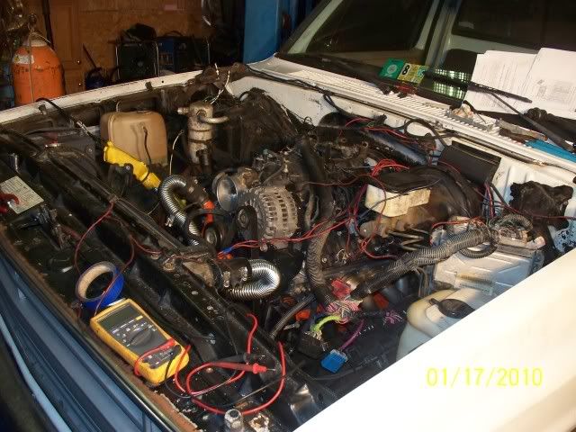
all right, i finally got the motor/trans shoved into the truck tonight. for mounting i am using ls to smallblock adaptors with the original clamshell truck mounts. i am reusing the th350 mount. i moved the motor mounts up a 1/4" to compensate for the adaptor plates. looks like im gonna have to move the crossmember forward an inch. i checked the driveshaft and still have plenty of engagement. here are some pics....


hello jomomma. keep up the good work. you mite be on the road b4 me. my '87 c10(5.3/4l60e) is in the shop be rewired. i had wires everywhere. in '87, c10's came with tbi. im having all that trash removed. please keep the pics of your conversion coming. its very inspiring. also r u upgrading anything? heads/cam. if so give me some ideas. power potential specs. very thanks. decc010974
Last edited by dec010974; Jan 15, 2010 at 08:14 PM. Reason: requesting info
Launching!
Joined: Nov 2005
Posts: 255
Likes: 0
From: Idaho (for now)
When I put the LQ4 in my 84 K25 Suburban all I did for motor mounts was build a 3/8" steel plate that extended forward about 2", bolted it to the 4 block bolt holes, set the motor in on the original buckets bolted to original mounts, after setting it in I just marked and trimmed the bucktes around the bolts and then welded the buckets to the steel plate. The 4L80E even bolted up in the same place as the 700R4 did - to easy!
it is almost too easy! well, i just got back in for the night. todays progress includes , reinstalling the fuel tank, running new fuel lines, pump and filter, fitting and welding out the exhaust. tomorrow i plan on tackling the wiring.
LS1 Tech Stories
The Best V8 Stories One Small Block at Time

Topdon ONE vs. Artidiag 800 BT2: Which is the Diagnostic Tablet For You?
Pouria Savadkouei
Gas Monkey Built a 6-Wheel Ferrari Testarossa With a Corvette LT4 Engine
Verdad Gallardo
7 Most Reliable High-Performance Engines GM Has Ever Built
Verdad Gallardo
Amazing '71 Camaro Restomod Is Modern Muscle Car Under the Skin
Verdad Gallardo
6 Common C5 Corvette Failures and What's Involved In Repairing Them
Pouria Savadkouei
Retro Modern Bandit Pontiac Trans AM Comes With Burt Reynolds' Autograph
Verdad Gallardo
Top 10 Greatest Cadillac V Series Performance Models Ever, Ranked
Pouria Savadkouei
Top 10 Most Powerful Chevy Trucks Ever Made!

Hennessey's New Supercharged Silverado ZR2 Has 700 HP
Verdad Gallardo i finally got some pics of the work i did this weekend.....
i just finished fitting the headers up. passenger side went on fine. drivers side, i had to clearance the frame rail just a little.
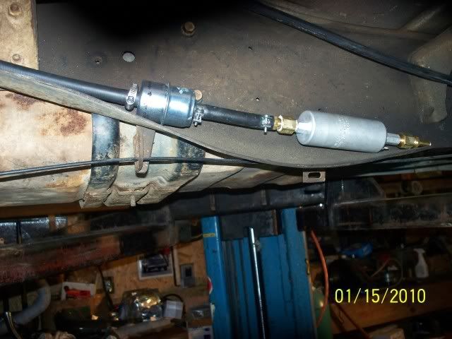
here, i fitted up the fuel filter and an inline walbro 255lph
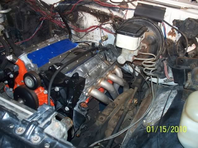
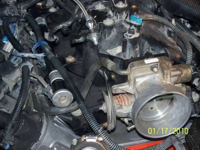
i just finished getting the intake on.
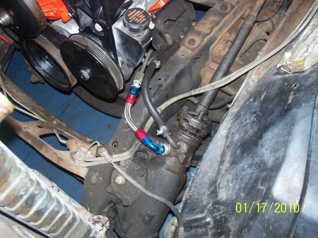
this is a pic of the power steering connection. i used a couple of metric to -6 an fiitings.
here, i am using a lokar 36" ls1 throttlecable to hook up to the throttlebody.
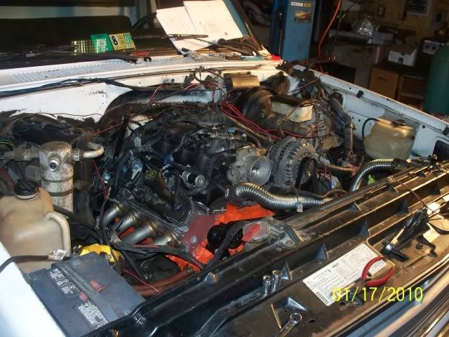
heres where i am currently. i still got some wiring to do!
i just finished fitting the headers up. passenger side went on fine. drivers side, i had to clearance the frame rail just a little.
here, i fitted up the fuel filter and an inline walbro 255lph
i just finished getting the intake on.
this is a pic of the power steering connection. i used a couple of metric to -6 an fiitings.
here, i am using a lokar 36" ls1 throttlecable to hook up to the throttlebody.
heres where i am currently. i still got some wiring to do!
Launching!
Joined: Nov 2005
Posts: 255
Likes: 0
From: Idaho (for now)
Launching!
Joined: Nov 2005
Posts: 255
Likes: 0
From: Idaho (for now)
Try this -
Blue connector
1 Ground BLK/WHT
2 Ignition LT GREEN (to crank position sensor)
3 Inj 3 PKN/BLK
4 Inj 2 LT GRN/BLK
5
6
7
8
9
10
11 KS Signal LT BLU
12 CKP DK BLU/WHT (to crank pos. sensor)
13 Req torque ORG/BLK (to electronic brake control module)
14 serial data ORG/BLK (to throttle actuator control module, fly by wire throttle)
15 serial data DK BLU/WHT (to throttle actuator control module, fly by wire throttle)
16
17 range b DK BLU (to transmission)
18 range c RED (to transmission)
19 ignition PNK (to fuse center)
20 B+ ORG/BLK (to fuse center, constant 20A fuse, ECMB fuse)
21 Ref low YEL (crank pos. sensor)
22
23 sens gnd PPL (EGR valve)
24
25 HO2S LO TAN
26 HO2S LO TAN
27
28 HO2S LO TAN/WHT
29 HO2S LO TAN/WHT
30 Coolant level LT GRN (on radiator)
31
32 PRND A BLK/WHT
33 BRK SW PPL (to black 14 pin connector then brake switch in car)
34 PRND P WHT
35
36 Inj 1 BLK/WHT
37 Inj 6 YEL/BLK
38 Lift Dive sig PNK/WHT (to suspension control module)
39
40 Ground BLK/WHT
41 Ground BLK (to transmission fluid temp sensor)
42
43 inj 7 RED/BLK
44 inj 4 LT BLU/BLK
45 +5V GRY (Fuel tank pressure sensor)
46 +5V GRY (TPS)
47 +5V GRY (MAP)
48 +5V GRY (EGR)
49
50
51 KS Signal
52
53 sens gnd (?)
54 sens gnd (?)
55 EGR input
56 Fuel Comp Sig (?)
57 B+ ORG (to fuse center, constant 20A fuse, ECMB fuse)
58 CLS 2 Data DK GRN (to OBD II diagnostic port pin 2)
59 CLS 2 Data YEL (to BCM fuel enable signal, serial data, VATS must be deleted in truck computers.)
60 sens gnd (?)
61 Ref low (?)
62
63 sens gnd (?)
64
65 HO2S HI
66 HO2S HI
67
68 HO2S HI
69 HO2S HI
70 Oil Level BRN (to oil switch in pan)
71
72 PRND B
73 CMP BRN/RED or BRN/WHT (to cam pos sensor)
74 ECT sig YEL (coolant temp signal, to sender in head)
75 Ignition PNK (to fuse center)
76 inj 5 BLK/WHT
77 inj 8 DK BLU/WHT
78
79 3-2 SS except 6.0L BRN or White
80 Sens rtn
RED connector
1 Ground BLK/WHT
2 TCC PWM BRN (to trans)
3
4
5 Delivered Torque TAN/BLK (to electronic brake control module)
6 PC SOL HI RED/BLK (to trans)
7 EGR Control RED
8 PC Sol Lo LT BLU/WHT (to trans)
9 Fuel Pump DK GRN/WHT (+12V power output for fuel pump relay to fuse center)
10 RPM out WHT (tach output 4cyl signal to black 14 pin connector)
11 Recirc Sw DK BLU (to 2 pin connector on passenger side of harness)
12
13 Cruise Eng LT BLU/BLK (to black 14 pin connector)
14
15 Gen L BRN
16 4WD Low GRY/BLK
17 AC REQ DK GRN/WHT
18
19
20 VSS Lo LT GRN/BLK (to VSS on side of trans)
21 VSS High PPL/WHT (to VSS on side of trans)
22
23
24 TP Sig DK BLU (to TPS sensor)
25 IAT SIG TAN (to mass air flow temp sensor)
26 Ign Ctrl PPL/WHT (coil )
27 Ign Ctrl RED or RED/WHT (coil )
28 Ign Ctrl LT BLU/WHT (coil )
29 Ign Ctrl DK GRN/WHT (coil )
30
31 MAF SIG YEL
32 MAP SIG LT GRN
33 Recirc Door DK GRN
34 Evap Can DK GRN/WHT (to solenoid on top of intake)
35
36
37
38
39 Ign Feed RED (cam pos sensor)
40 GND BLK/WHT
41 EGR GND WHT
42 TCC SOL TAN/BLK except 6.0L (to trans)
43 A/C CLU DK GRN/WHT
44
45 EVAP Vent WHT (pin C of blue 12 pin plug)
46 MIL Ctrl BRN/WHT (to black 14 pin connector chk engine light)
47 2-3 SS YEL/BLK
48 1-2 SS LT GRN
49 VSS Out YEL/BLK (pin E of blue 12 pin connector)
50 VSS Out DK GRN/WHT (to black 14 pin connector)
51 TFT Sens Sig YEL/BLK (to trans fluid temp)
52 Gen F GRY (2000 only)
53
54 Fuel Lev PPL (to pin K of blue 12 pin connector)
55 CYC SW in DK GRN (A/C system)
56
57 SENS GND BLK
58
59
60 REF Low BRN (to ign coils)
61 REF Low BRN/WHT (to ign coils)
62 PRND C GRY (to trans)
63 TRANS RNG A PNK (to trans)
64 Fuel SIG CTRL DK GRN (pin D of 12 pin blue conector, to fuel tank pressure sensor)
65
66 IGN CTRL PPL/WHT (coil )
67 IGN CTRL RED/WHT (coil )
68 IGN CTRL DK GRN (coil )
69 IGN CTRL LT BLU (coil )
70
71
72
73
74
75
76 IAC COIL HI LT GRN/WHT
77 IAC COIL LO LT GRN BLK
78 IAC COIL LO LT BLU/BLK
79 IAC COIL HI LT BLU/WHT
80 ORG/BLK (pin G of 12 pin blue connector)
Black 14 pin connector. Not labled a-n, just identify order by wire color/placement.
A blu/blk pin 13 cruise engage Depends
B wht Power steering pump pressure sensor No
C pnk canister evap vent Depends
D grn pin 50 VSS out Depends
E ppl pin 33 TCC Break switch If using 4l60e/ 80e yes
F brn/wht MIL control Yes
G Grn pin 58 serial data Yes
H tan/wht oil pressure Depends
I wht pin 10 Tachometer Depends
J brn Power steering pump pressure sensor No
K yel VATS No unless using BCM
L brn 4wd low No
M grn A/C recirc. No
N grn/blk to fuse center Me no, but you ?????????
Blue 12 pin plug
A
B
C Gry pin 45 evap vent Depends
D grn pin 64 fuel signal control Depends
E yel/blk pin 49 VSS out Depends
F wht pin 45 EVAP vent Depends
G orng/blk Pin 80 Blue connector No idea what it does??????????????
H
J blk pin 53 Blue ????????????????????????
K ppl pin 54 Fuel level Depends
L
M
2 Pin black connector is fo 4WD low range Not used
Large Black plug for fuse box. Not labled just follow diagram to find wires
Pnk Injection 2&4 Yes
blk ground Yes
pnk coils odd Yes
pnk ignition 1 Yes
ppl Starter Depends
yel PRND switch No
pnk Injection 1&3 Yes
pnk injection 5&7 Yes
ppl/wht PRND No
grn PRND No
pnk PRND No
Orng Battery Yes
pnk Front o2 Yes
pnk Rear o2 Depends
dk grn/wht Fuel pump relay Yes
pnk evap purge Depends
pnk injectors 6&8 Yes
blk Ground Yes
pnk coils even Yes
blk/wht ground Yes
LT Blue A/C Depends
pnk MAF Yes
drk blu A/C recirc. No
Grn A/C compressor Depends
LT grn PRND No
grn/blk to blk connector No/Depends
pnk evap vent Depends
pnk Ignition 2 pin 75 Yes
This is info that I've collected - it is not my own work.
Launching!
Joined: Nov 2005
Posts: 255
Likes: 0
From: Idaho (for now)
Or this -
Wires removed from 2001 A4 harness for conversion
________________________________________
Okay, checked out my wiring harness conversion and found quite a few wires removed.
2001 LS1 5.7L with 4L60E A4 Transmission
Blue connector....
23 - Low Reference
25 - HO2S Low Signal Bank 2 Sensor 2
28 - HO2S Low Signal Bank 1 Sensor 2
32 - CPP Switch Signal ? what is CPP?
65 - HO2S High Signal Bank 2 Sensor 2
68 - HO2S High Signal Bank 1 Sensor 2
70 - Oil Level Switch Signal
Red Connector....
4 - Air Injection Reaction Solenoid Relay - Coil - Control
13 - Cruise Control Engage Signal
34 - Evaporative Canister Purge Solenoid Control
36 - AIR Pump Relay Control
37 - Cruise Control Inhibit Signal
45 - Evaporative Canister Vent Solenoid Control
46 - MIL Control ? what does MIL stand for?
53 - Ignition Retard Signal
54 - Fuel Level Sensor Signal
64- Fuel Tank Pressure Sensor Signal
2001 LS1 5.7L 4L60E four speed automatic
Removed pins and wires from Blue PCM connector....
23, 25, 28, 32, 65, 68 and 70
Removed pins and wires from Red PCM connector....
4, 7, 13, 34, 36, 37, 45, 53, 54 and 64
Bundle these wires together and route into the cab of vehicle.....
Blue 33 - Purple - TCC Brake Switch Signal - to brake switch - normal 12v positive and Zero
Volts when brake pedal is depressed .
Blue 34 - Orange/Black - Neutral Safety Switch
Blue 46 - Brown/White - Malfunction Indicator Light
Red 17 - Green/White - A/C request switch
Red 30 - Dk Blue - Fuel Enable Control - to VATS if not disabled in the PCM
Red 42 - Tan or Tan/Black - TCC Solenoid Valve Control
Red 50 - Green/White - Vehicle Speed Sensor Signal
Six fuse power block....
12V - Red - always "ON" from battery to three fused outlets
1. 30 amp 12V from fuse to terminal 87 for low fan relay
2. 30 amp 12V from fuse to terminal 87 for high fan relay
3. 10 amp 12V from fuse to PCM Blue 20 and 57
12V - Pink - from ignition "ON" switch to three fused outlets
1. 20 amp 12V from fuse to A/C relay terminal 87
2. 15 amp 12V from fuse to PCM Connector Blue 19
3. 15 amp 12V from fuse to Fuel Pump Relay terminal 87
Bosch Type Relay 1.
Low Speed Fan Relay
Terminal 85 connect to PCM Blue 42 - Dark Green
Terminal 30 Connect to Fan positive
Terminal 86 Connect to constant 12V Power Supply
Terminal 87 Connect to Switched 12V Power Supply
Bosch type Relay 2.
High Speed Fan Relay
Terminal 85 connect to PCM Red 33 - Dark Blue
Terminal 30 Connect to Fan positive
Terminal 86 Connect to constant 12V Power Supply
Terminal 87 Connect to Switched 12V Power Supply
Bosch type Relay 3.
Fuel relay
Terminal 85 connect to PCM Red 9 - Dark Green/White
Terminal 30 Connect to fuel pump 12V input
Terminal 86 Connect to Ground - black/white
Terminal 87 Connect to Switched 12V Power Supply
Bosch type Relay 4.
A/C relay
Terminal 85 connect to PCM Red 43 - Green/White - A/C Clutch Relay Control
Terminal 30 Connect to PCM Red 18 - Dark Green - A/C Compressor Clutch Supply Voltage
Terminal 87 Connect to switched 12V Power Supply
Terminal 86 Connect to PCM Blue 19 - Pink - Ignition 1 Voltage
My only concern is Relay 4. I don't see the logic there. It seems to me that Terminal 86 - Blue 19 - should have 12 Volts at the switch unless it is 12 Volts output from the PCM instead of input into the PCM. GM has always used the pink wire as switched power, red as constant 12V and Purple as the main starter solenoid lead.
Posted by
Magnus
Re: wiring questions
________________________________________
Hmm.. ok Lets go over the list..
Oil Pressure: Optional but recommended
Clutch Anticipate Switch Signal: uncertain
IGN Power for TCC Stop Lamp Switch: Optional but recommended
TCC/Cruse Brake Switch: Optional but recommended (Paired with above)
Ground
PNP Switch Signal: Optional
Low Coolant Indicator: Optional
VSS Output: Optional but recommended
5V Feed (Fuel tank pressure): Optional
MIL Control: Optional but recommended
EVAP Canister Vent Valve Control: Optional
Theft Deterrent Fuel Enable: Required
A/C Request: Optional
Fuel Ground: Optional depending on how your fueling is setup
Fuel Tank Pressure: Optional
Fuel Level Input: Optional
Serial Data (Class 2): Optional but recommended
Hot in Run and Start (IGN/INJ Bank 1 15A): Required
A/C Clutch Relay Control: Optional
A/C Clutch Status: Optional
TPS +5v to TCS: Optional
TPS signal to TCS: Optional
with IGN 1 Relay Engaged (Tranny/EGR 15A): Required
Cooling Fan 2 and 3 Relay Control: Optional but HIGHLY recommended
Cooling Fan 1 Relay Control: Optional but HIGHLY recommended
TPS sensor low to TCS: Optional
Low Coolant Sensor: Optional
Hot in Run and Start (IGN/INJ Bank 2 15A): Required
Air Pump Relay Control: Optional
Fuel Pump Relay Control: Required most likely
Ignition Positive Voltage for PCM: Required
Battery Positive Voltage for PCM: Required
Ground:
TCS Spark Retard Signal to Brake Control Module: Optional
Hot with IGN 1 Relay Engaged (TCC Stop Lamp Switch/MAF/O2 20A): Required
Cruise Control Inhibit: Optional
Cruise Engaged Signal: Optional
Tach out to Brake Control Module: Optional (Re-use for dash tach)
AIR Solenoid Relay Control: Optional
Posted By
MrDude_1
let me take a min to explain what that means (i know i wish someone did that for me first.. lol)
when you get a pullout that has the harness on the car, everything is connected except:
3 connectors that were underhood. (named C100,C101,C105)
2 connectors that used to connect under the dash (220,230)
so these 5 connectors are teh ONLY wires we're worred about.
in a nutshell... give ignition power to the pink wires, constant power to the orange ones, take off VATS, and it runs.
the other wires you hook up are just gauge wires, reverse lights, ect.... nothing hard.
its ALMOST a stand alone harness already... only diff is it will have a couple extra wires left after its hooked up.. not a big deal..
theres one more wire not listed there.. its a thick purple wire that goes to the starter.
when it gets +12v, the starter turns the motor over.
also, i bought HPtuners... you will either need HPtuners, or have your PCM flashed to remove the trouble codes and VATS.... if you buy HPtuners, this is NOT hard to do.. i could give you a step by step on doing it easily.... but HPtuners is a little pricy. a tune is a cheaper route, but HPtuners gives you the scanner thats very useful.. along with the ability to change stuff at will... your call on that.
Quote:
Originally Posted by SatisTraction
did any of you leave the diagnostic plug connected so taht you could connect a tuner for the computer?
yup.
all i did was go into the junkyard and grab one off of a GM ODBII car.....
https://ls1tech.com/forums/conversio...chmentid=30711
posted by flippincamaro
hey here are the wires you need
99 LS1 PCM to Front Harness
Large Plug C100 Plug
A PNK Hot in Run and Start (IGN/INJ Bank 1 15A)
B DK GRN/WHT PCM 43 A/C Clutch Relay Control
C DK GRN PCM 18 A/C Clutch Status
D GRY TPS +5v to TCS
E DK BLU TPS signal to TCS
G PNK Hot with IGN 1 Relay Engaged (Tranny/EGR 15A)
H DK BLU PCM 33 Cooling Fan 2 and 3 Relay Control
J DK GRN PCM 42 Cooling Fan 1 Relay Control
K BLK TPS sensor low to TCS
C101 Plug
A YEL/BLK Low Coolant Sensor
B PNK Hot in Run and Start (IGN/INJ Bank 2 15A)
C BRN PCM 36 Air Pump Relay Control
D DK GRN/WHT PCM 9 Fuel Pump Relay Control
E PNK/BLK PCM 19 Ignition Positive Voltage for PCM
G ORN PCM 57 Battery Positive Voltage for PCM
H BLK/WHT Ground
K GRY/BLK PCM 53 TCS Spark Retard Signal to Brake Control Module
C105 Plug
B PNK Hot with IGN 1 Relay Engaged (TCC Stop Lamp Switch/MAF/O2 20A)
D DK GRN PCM 37 Cruise Control Inhibit
F WHT PCM 13 Cruise Engaged Signal
G WHT PCM 10 Tach out to Brake Control Module
H PPL PCM 4 AIR Solenoid Relay Control
These are all of the pins/wires I did not use:
220- E,H,J,K
230- A,C,F,G,H,J
C100- B,C,D,E,K
C101- A,C,K
C105- D,F,H
All the pink wires run into one wire which is ignition switch on i ran it to my ecm ignition on fuse on my truck fuse box. and the orange wire i ran a hot wire to it from my battery.
This is info that I've collected - it is not my own work. Thanks to the people responsible for all of this - it helped me a lot!
jomomma, why didnt you install the walbro in the tank? on my conversion thats what i did. the fuel keeps the pump cooler and you eliminate that winding pump noise. i hated the sound of the holley blue before i converted to the 5.3/4l60e. the only time i hear the pump is when i turn the key to the on position when the fuel system pressurizes.
i just had one sitting in my shop, so i used it. i dont think the inline walbro is very noisy. im sure the in tank version is much quieter though! and genIIIdude, your a freakin life saver. i think i can work with this info! and i have a data port also.
Launching!
Joined: Nov 2005
Posts: 255
Likes: 0
From: Idaho (for now)
