
1933 Ford Coupe/Roadster Stroker Build

 06-23-2011, 08:12 AM
#62
TECH Enthusiast
Thread Starter
iTrader: (10)

Join Date: Jun 2010
Location: Boston
Posts: 728
Likes: 0
Received 0 Likes
on
0 Posts

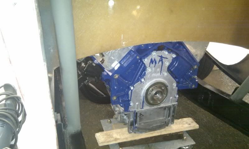
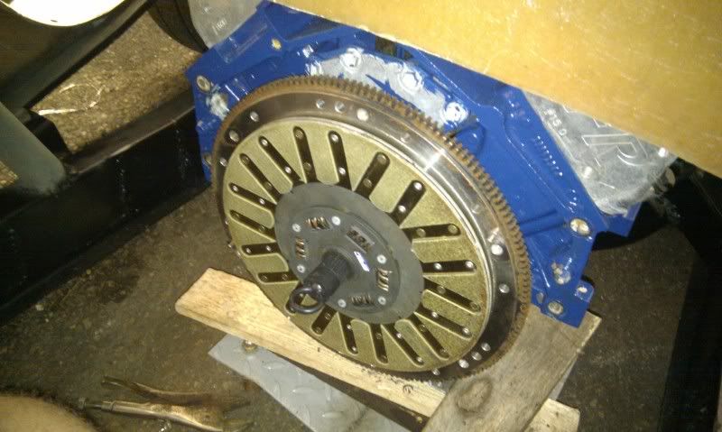
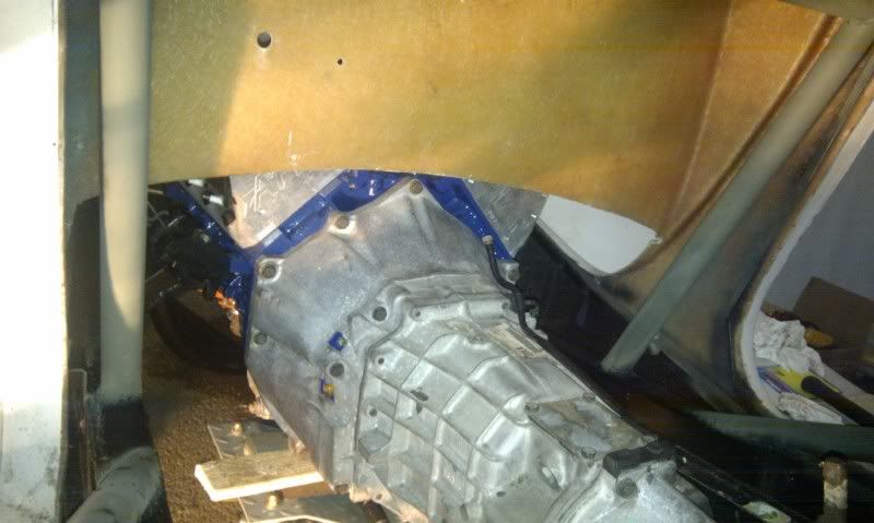
Got the pilot bearing flywheel/clutch/pp on. To make the pilot bearing install easier, i put it in the freezer overnight, and then added some bearing grease to the outside and inner of the crank. I then had a little trouble since i crossthreaded on of the holes on the flywheel but fixed it and was on a roll from there. Got the bell housing on and the tranny, followed by the driveshaft. Let me tell you it was fun picking up the tranny and lifting it over my door bars into the car.
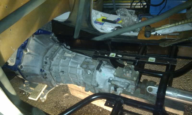
I'm picking up bolts for the new tranny mount after work, once thats installed i'll get the steering column and pedal assembly mounted[need to fab the mounts] and then i can start on my headers and make my tuning/break-in appointment.
I'm picking up bolts for the new tranny mount after work, once thats installed i'll get the steering column and pedal assembly mounted[need to fab the mounts] and then i can start on my headers and make my tuning/break-in appointment.
Last edited by Marcello7x; 06-23-2011 at 08:19 AM.
06-23-2011, 08:15 AM
#63
TECH Enthusiast
Thread Starter
iTrader: (10)
Join Date: Jun 2010
Location: Boston
Posts: 728
Likes: 0
Received 0 Likes
on
0 Posts
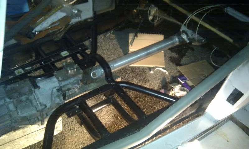
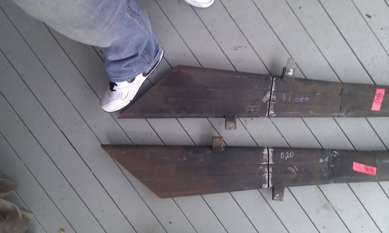
A quick before and after of the frame K member, the before is a 2x4 .125 steel tube cut in half, bent and welded. The two sides of the frame where connected via the tranny mount. The new obviously 1.75 DOM .125 thick! Night and day difference.
This is just the before, the after is ^^^
This is just the before, the after is ^^^
06-24-2011, 07:29 AM
#64
TECH Enthusiast
Thread Starter
iTrader: (10)
Join Date: Jun 2010
Location: Boston
Posts: 728
Likes: 0
Received 0 Likes
on
0 Posts
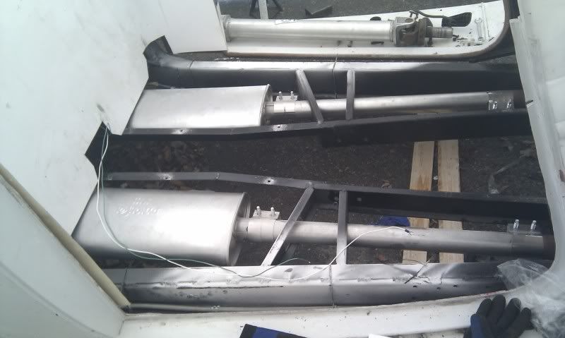
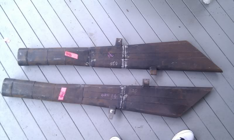
Boom tubes are in!!! These things are hugeee: Yea they have a cut in them, i guess they had to make some cuts to get them off the car[ they were on a legit racing NASCAR] Easy fix, and for only $25 a piece i can't complain, but the neighbors sure will!!
Next up on my list of stuff to do is get my steering columb in/ pedal assembly and linkage done. Pedals have very little room and the steering has the go right between pedals.
Next up on my list of stuff to do is get my steering columb in/ pedal assembly and linkage done. Pedals have very little room and the steering has the go right between pedals.
06-25-2011, 08:52 PM
#65
TECH Enthusiast
Thread Starter
iTrader: (10)
Join Date: Jun 2010
Location: Boston
Posts: 728
Likes: 0
Received 0 Likes
on
0 Posts
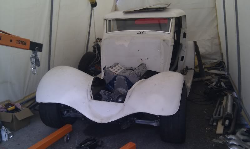
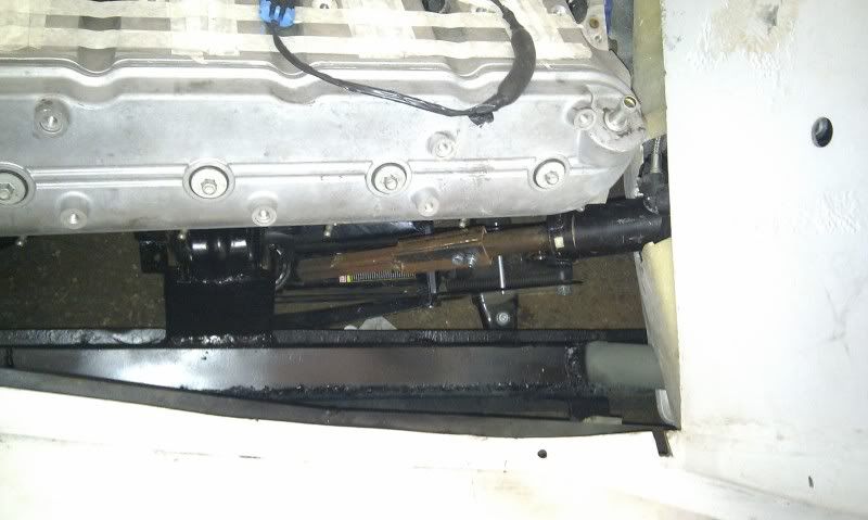
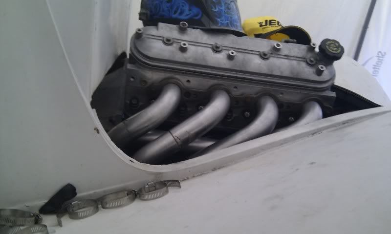
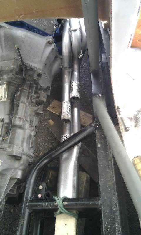
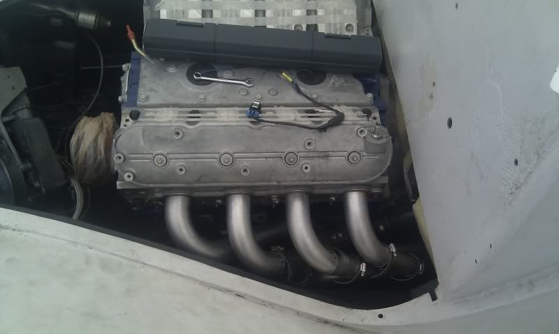
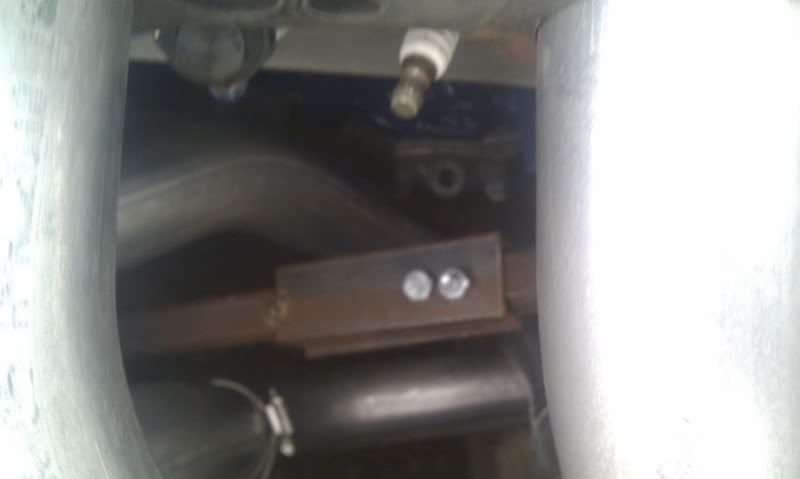
So today in the process of making brackets for the pedals and steering i realized the floor could no longer come out. I currently have in split right before the seats, so just that section would be permanent. With that in making my headers would be a huge PITA. So i jumped right to the headers. I was a little apprehensive because i new the driver-side was going to be difficult. Here is the space i have to deal with. Im building 1 7/8 headers, and they need to fit around the steering rod.
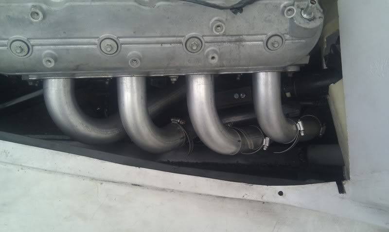
Seeing this i decided the passenger side would be good practice. Took from about 11am till 5pm with one redbull run and one homedepot run. They are only tacked together, nothing is permanent yet. Final welding will all be done once the driver is done.
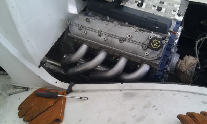
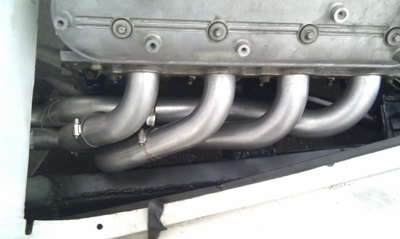
Seeing this i decided the passenger side would be good practice. Took from about 11am till 5pm with one redbull run and one homedepot run. They are only tacked together, nothing is permanent yet. Final welding will all be done once the driver is done.
06-25-2011, 08:57 PM
#66

I think the pass side header turned out (thus far) good.
06-27-2011, 07:29 AM
#71
TECH Enthusiast
Thread Starter
iTrader: (10)
Join Date: Jun 2010
Location: Boston
Posts: 728
Likes: 0
Received 0 Likes
on
0 Posts
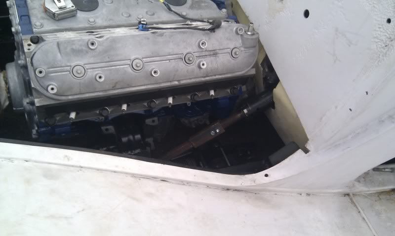
Here is where im at on the driver side. Def took a bit more of cutting and playing around with, but im almost there. I haven't gotten the ends to align up at the header yet, im still working on clearance and neatness around the steering.
That steering linkage is temporary, but makes a good placeholder since it should be at the very least was wide as my real one will be.
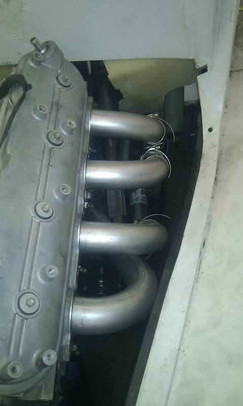
That steering linkage is temporary, but makes a good placeholder since it should be at the very least was wide as my real one will be.
06-27-2011, 07:54 AM
#72
TECH Enthusiast
Thread Starter
iTrader: (10)
Join Date: Jun 2010
Location: Boston
Posts: 728
Likes: 0
Received 0 Likes
on
0 Posts
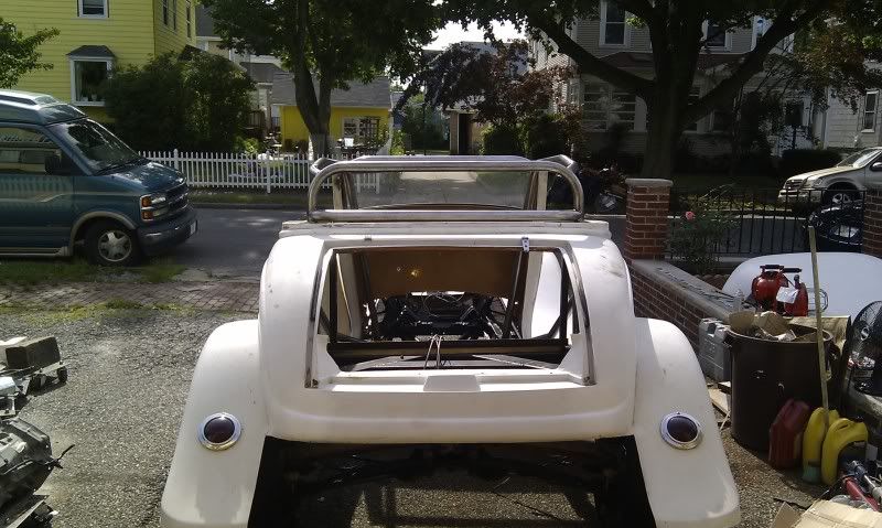
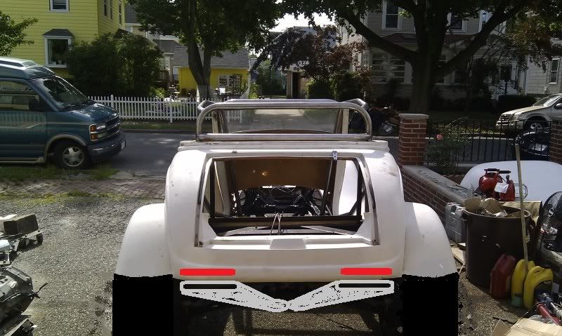
I also discovered i can't place my boom tubes out the side of the car before the rear tires. To do so the cutout would have to come down right at the collector, and would hang 3 inches above the ground. Cutouts are going back to about 2ft before the rear tires, and i may use the boom tubes as a crazy exhaust tip coming up from under my dif up to right under my bodyline.
Kind of like these on fbodies[sry if its your pic and don't want it used, msg me and i'll take it down] except spread to match up with the LED tails im going to use.
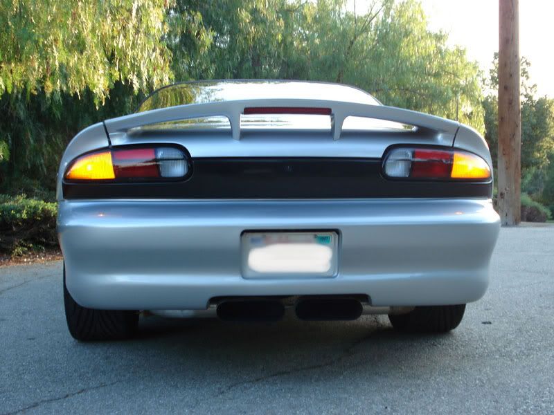
Here is a before and after of what im planning. Fender cut shorter, Tails and tubes painted in.
Kind of like these on fbodies[sry if its your pic and don't want it used, msg me and i'll take it down] except spread to match up with the LED tails im going to use.
Here is a before and after of what im planning. Fender cut shorter, Tails and tubes painted in.
06-27-2011, 10:14 AM
#73
Launching!

Join Date: Jan 2011
Location: Arizona
Posts: 200
Likes: 0
Received 0 Likes
on
0 Posts
I'm sure you've thought about it, but having built headers for circle track cars, having the header wrap around the steering shaft is tricky. You need slip joints in that tube of the header so that it can be removed, or at the very least a steering shaft that is easily removed, a collapsible one works best. One time i built a header and thought i could remove the steering shaft, only to realize after it was done that the shaft bound between everything and didn't come out. so out came the sawzall. just my two cents worth.
Car is going to be quick with no weight and a lot of power, should get you into a lot of trouble. and that's just how i like em'.
props for taking on a lot of this yourself. that's how it was done years ago.
Car is going to be quick with no weight and a lot of power, should get you into a lot of trouble. and that's just how i like em'.
props for taking on a lot of this yourself. that's how it was done years ago.
06-27-2011, 12:04 PM
#74
TECH Enthusiast
Thread Starter
iTrader: (10)
Join Date: Jun 2010
Location: Boston
Posts: 728
Likes: 0
Received 0 Likes
on
0 Posts
Yea i realized removing might be an issue, the plan was removing the whole steering columb. but then i realized i need a coupler and shaft extention, so if i shorten the current shaft and place the coupler further up ill havr more clearance and can remove the extention when removing the headers.
06-29-2011, 07:33 AM
#75
TECH Enthusiast
Thread Starter
iTrader: (10)
Join Date: Jun 2010
Location: Boston
Posts: 728
Likes: 0
Received 0 Likes
on
0 Posts
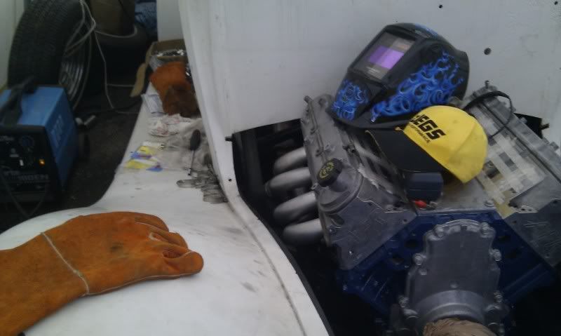
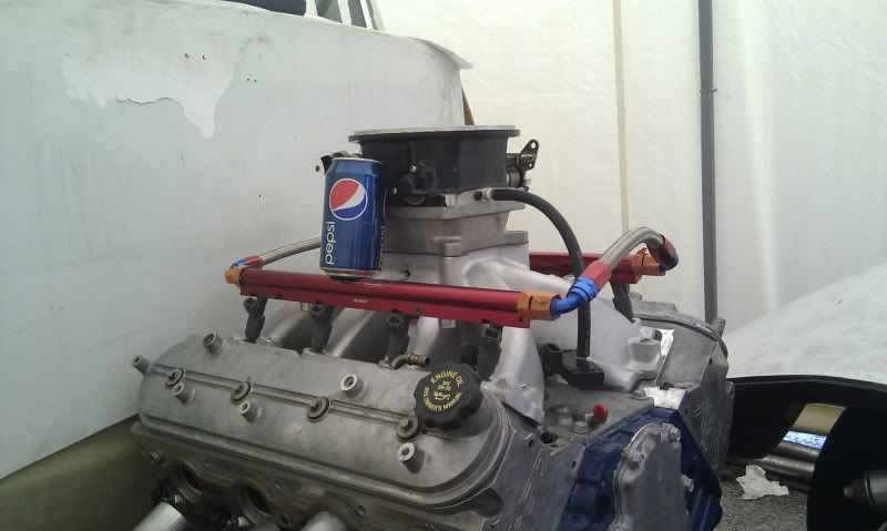
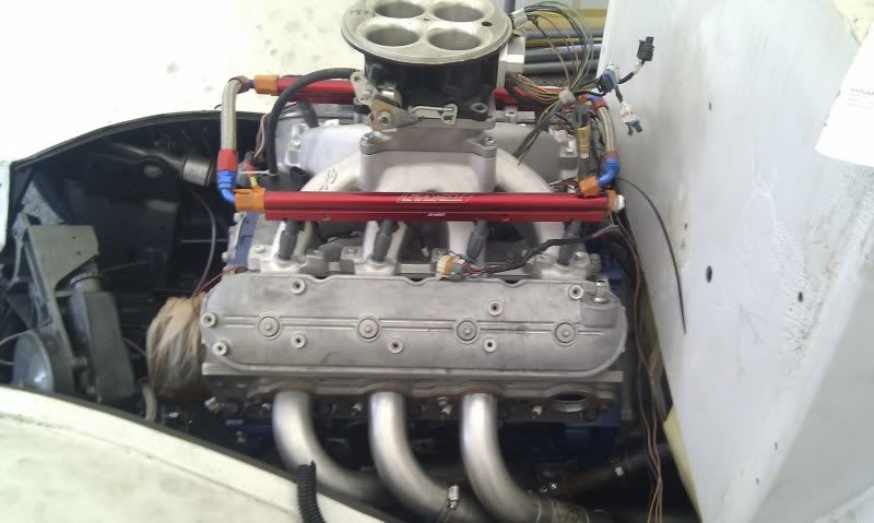
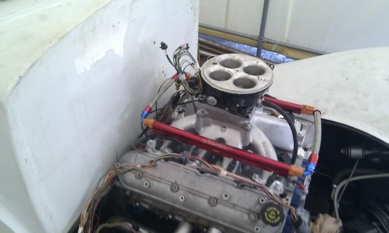
Not much done yesterday since i ran out of alignment sleeves. Should have more by tomorrow. Meanwhile the motor started to get some parts on it. Finally looks like something that will run soon. A little taller than i expected, i still need to add in the nitrous plate. Anyone know one thats maybe only a half inch??
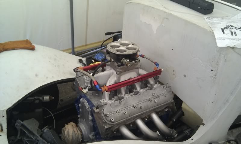
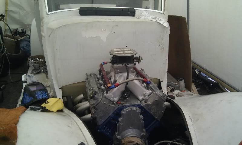
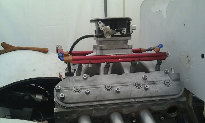
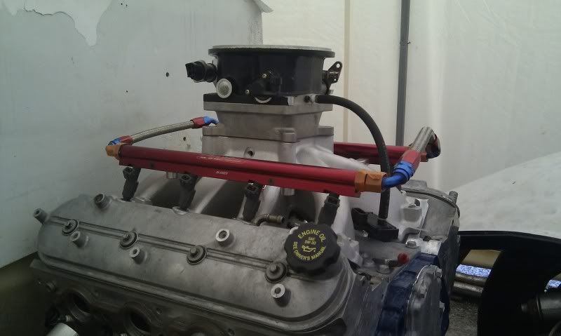
Height comparison photo.
Height comparison photo.
06-29-2011, 07:44 AM
#76
TECH Enthusiast
Thread Starter
iTrader: (10)
Join Date: Jun 2010
Location: Boston
Posts: 728
Likes: 0
Received 0 Likes
on
0 Posts
This was posted in another thread asking for advice on exhaust, figured i would import it to here for anyone who follows along.
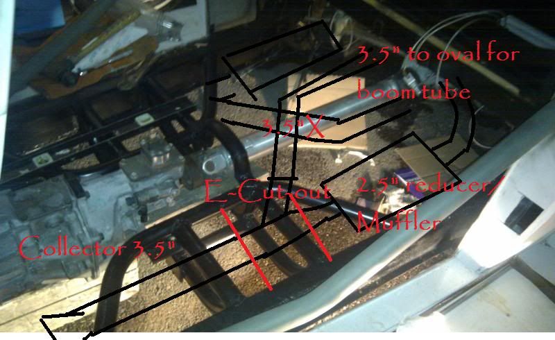
1 7/8 custom lt headers to 3.5" collector
3.5" piping for about 2.5ft with a cutout to a boom tube
3.5" to 2.5" reducer
2.5" dynomax superturbo mufflers[longer version]
then merged into the side of the boom tube
This was then revised to add an X pipe post cutout for scavenging, and the cutout would be the bypass loop around the muffler and both would come out of the boom tube. The convenient part is the boom tube has oval tubing, 4x2.5, and i'll have 2.5 out of the muffler so i will create a custom merger. The boom tube will amplify sound a bit, but im expecting duel dynomax superturbo mufflers, the longer version, should attenuate it enough to not make a drastic difference. The cutouts on the otherhand will take a slight 45* bend into the X then strait back into the tube AKA deafening loud for anyone behind me.
Here is a quick paint i did of how it will layout.
06-29-2011, 07:46 AM
#77
TECH Enthusiast
Thread Starter
iTrader: (10)
Join Date: Jun 2010
Location: Boston
Posts: 728
Likes: 0
Received 0 Likes
on
0 Posts
This is the X pipe kit i purchased. The only 3.5" X that wasn't absurdly expensive. It also comes with the extra tubing i need as well. I did consider making my own X but the money i would have saved would not have been worth the time since im rallying to get it on the road asap.
http://www.pysales.com/iw_products.m...14?company=ppe

http://www.pysales.com/iw_products.m...14?company=ppe
06-30-2011, 10:57 AM
#79
TECH Enthusiast
Thread Starter
iTrader: (10)
Join Date: Jun 2010
Location: Boston
Posts: 728
Likes: 0
Received 0 Likes
on
0 Posts
Thanks, im hopefully going to have it broken in and running in a couple of weeks. Im between the exhaust and wiring right now.
He hasn't bought anything yet, but we're looking to buy a rallycross car, prob an MK1 VW golf or jetta.
He hasn't bought anything yet, but we're looking to buy a rallycross car, prob an MK1 VW golf or jetta.
06-30-2011, 11:04 AM
#80
TECH Enthusiast
Thread Starter
iTrader: (10)
Join Date: Jun 2010
Location: Boston
Posts: 728
Likes: 0
Received 0 Likes
on
0 Posts
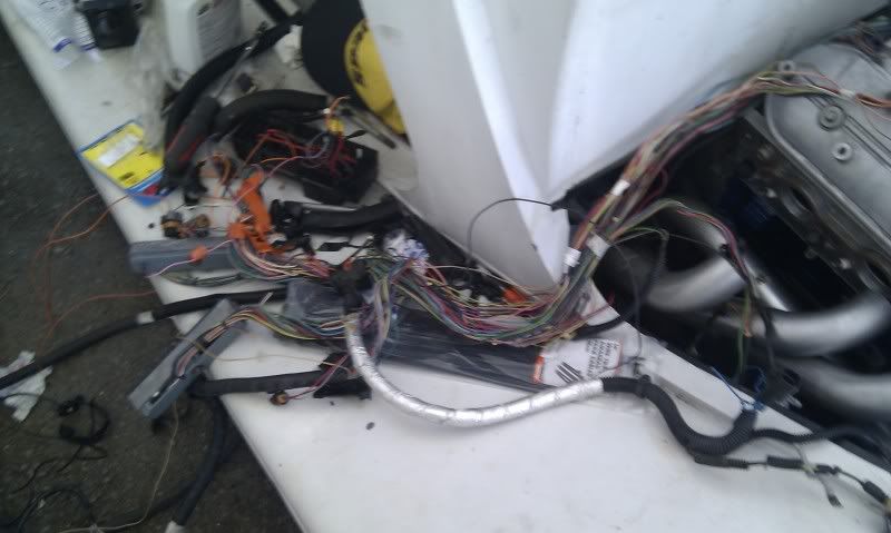
Here are some pics from yesterday, since i was held back on my headers i figured i would start the wiring harness modes. Since i had it running once, i just wanted to clean up all the extra crap that wasn't needed but left on. Im going to try and hide as much of the wiring as possible.
This is the driver side with the injector wires under the intake. The coil pack connector will get routed somewhere under the car i believe
Im going to extend the pas side injector/cam wires to get them up and behind the engine.
A pic of some of the removed stuff
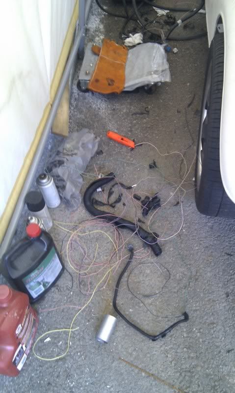
And a big ball of mess. Will get sorted out, all the interior connectors will stay on for now, im not sure what i will be using or not yet.
This is the driver side with the injector wires under the intake. The coil pack connector will get routed somewhere under the car i believe
Im going to extend the pas side injector/cam wires to get them up and behind the engine.
A pic of some of the removed stuff
And a big ball of mess. Will get sorted out, all the interior connectors will stay on for now, im not sure what i will be using or not yet.