

'70 Nova LY6/TH400 6.0VVT

Thread Starter


Joined: Apr 2010
Posts: 2,816
Likes: 86
From: Instagram @chevyhotrodder
For documentation's sake, here is an email response I got from Kurt from Autokraft when asking what dipstick to use and what he thought of my 1/4" forward plan.
I'm happy to hear his thoughts on the 1/4" forward. Hopefully he's right!
We recommend using an f-body dipstick and tube (98-02 camaro/firebird)
I cant see why you couldn't move the engine 1/4in. There should be enough clearance for that.
When we first starting selling the conversion pans, we found that most aftermarket tie rods had the zerk fitting on the end of the tie rod which in some cases hit the corner of the pan. The factory original ones had the zerk on the face of the tie rod so clearance was not an issue. We just notched the pan on the corner of the sump so no matter what it clears with no issues. We changed that about 4-5 years ago

I think that trailblazer a/c compressor trick will work on my ls3 build.Looking on car-part.com they show a different compressor for the 2007 and up. Maybe it has to do with the vvt timing cover I don't know.Do you happen to know the year of the compressor that you used . How about the year of the a/c bracket or maybe the part number.Thanks
Thread Starter
Joined: Apr 2010
Posts: 2,816
Likes: 86
From: Instagram @chevyhotrodder
The AC Compressor was listed for an '03 to '07 Trailblazer 5.3 or 6.0. I don't remember exactly what year I looked up for the bracket, but any of those should work.
I'm not sure if the LS3 4 groove section of the crank pulley is spaced the same distance from the block as the truck crank pulley. I know the 6 groove section is closer to the block. Depending on where it's located, things may not line up.
I'm not sure if the LS3 4 groove section of the crank pulley is spaced the same distance from the block as the truck crank pulley. I know the 6 groove section is closer to the block. Depending on where it's located, things may not line up.

Looking good Clint. I'm glad I checked your build when I did. I've been wondering what I was going to do for a dipstick also, and you've answered it for me. I also agree with the stock spacers. Unless you want to modify everything, they need to go back in. I found the same issue when I started to put the fenders on without them. Things wouldn't line up. Keep the updates coming.
Thread Starter
Joined: Apr 2010
Posts: 2,816
Likes: 86
From: Instagram @chevyhotrodder
The last couple of months have been a blur. It's amazing how having a kid changes your life. Free time is rare!
Here and there I've plugged away at the car. First, here are some spacers I cut from 1/2" aluminum using a hole saw to add to the solid bushings supplied by Global West. Novas of my generation (I believe from '68 to '72) need this spacer for proper frame and body alignment. Somewhere around '73 they went to a thicker rubber bushings and elminated this spacer, but if you are going to an aftermarket solid body bushing normally meant for a Camaro, you will need to add a spacer at the firewall mounts for '68-'74 Novas. You'll also need 1/2" longer bolts than what is supplied with the aftermarket bushings, unless you are reusing your originals.

With things down to the frame, I decided now would be a good time to address some of the suspension shortcomings that I was fighting at autocross last year. First, it's well documented that the camber curve for 1st gen Camaros and 3rd gen Novas like mine is a bit backwards. There are a host of ways to correct this and I decided to do the rather popular Guldstrand mod. This moves the upper control arm frame mounting points down a bit to primarily increase negative camber on compression ("camber gain"). If you want to learn more about this, do some searching because it's been discussed in detail elsewhere.
I started by pulling apart the suspension. I supported the weight of the car with a jack near the balljoint on the lower control arm, then loosened the upper balljoint, used a seperator to get it to "pop" while the nut was still on the end, then simply loosened the nut until it came loose. There was a little bit of spring energy left when the nut came off, but not much - the car moved up only a little bit. Now I realize this is not safe to do on all vehicles, but in this case it worked out fine. I had left the shock in place just in case things decided to go flying anywhere. Finally I put a jackstand under the front of the frame and lowered the jack to release the spring.


I've decided to do the G-mod the "hard way". Rather than drilling a second set of mounting holes lower on the UCA towers, I am going to cut the towers off at their base and weld them in at the new location. First I used a c-clamp and a socket to remove the studs for the upper control arms.

I then cut a few pieces from 2-1/2 x 1/8 bar

I bought the actual template directly from Dick Guldstrand's shop. You can download copies of it off the net, but I like to support the people that develop these things and this way I was assured I had the right dimensions. Here I use a punch to transfer the hole locations to a piece of flat.

After drilling the four 7/16" holes, I trimmed the lower portion of the plate to follow the flat contoured section of the UCA tower. The new location for the lower hole is very close to a curved potion of the tower, so I ground it at an angle on the backside so the plate would sit flat.

Here is the relocation plate now bolted on both sides

Next I made plates that bolt to the motor frame stand locations.


Here and there I've plugged away at the car. First, here are some spacers I cut from 1/2" aluminum using a hole saw to add to the solid bushings supplied by Global West. Novas of my generation (I believe from '68 to '72) need this spacer for proper frame and body alignment. Somewhere around '73 they went to a thicker rubber bushings and elminated this spacer, but if you are going to an aftermarket solid body bushing normally meant for a Camaro, you will need to add a spacer at the firewall mounts for '68-'74 Novas. You'll also need 1/2" longer bolts than what is supplied with the aftermarket bushings, unless you are reusing your originals.
With things down to the frame, I decided now would be a good time to address some of the suspension shortcomings that I was fighting at autocross last year. First, it's well documented that the camber curve for 1st gen Camaros and 3rd gen Novas like mine is a bit backwards. There are a host of ways to correct this and I decided to do the rather popular Guldstrand mod. This moves the upper control arm frame mounting points down a bit to primarily increase negative camber on compression ("camber gain"). If you want to learn more about this, do some searching because it's been discussed in detail elsewhere.
I started by pulling apart the suspension. I supported the weight of the car with a jack near the balljoint on the lower control arm, then loosened the upper balljoint, used a seperator to get it to "pop" while the nut was still on the end, then simply loosened the nut until it came loose. There was a little bit of spring energy left when the nut came off, but not much - the car moved up only a little bit. Now I realize this is not safe to do on all vehicles, but in this case it worked out fine. I had left the shock in place just in case things decided to go flying anywhere. Finally I put a jackstand under the front of the frame and lowered the jack to release the spring.
I've decided to do the G-mod the "hard way". Rather than drilling a second set of mounting holes lower on the UCA towers, I am going to cut the towers off at their base and weld them in at the new location. First I used a c-clamp and a socket to remove the studs for the upper control arms.
I then cut a few pieces from 2-1/2 x 1/8 bar
I bought the actual template directly from Dick Guldstrand's shop. You can download copies of it off the net, but I like to support the people that develop these things and this way I was assured I had the right dimensions. Here I use a punch to transfer the hole locations to a piece of flat.
After drilling the four 7/16" holes, I trimmed the lower portion of the plate to follow the flat contoured section of the UCA tower. The new location for the lower hole is very close to a curved potion of the tower, so I ground it at an angle on the backside so the plate would sit flat.
Here is the relocation plate now bolted on both sides
Next I made plates that bolt to the motor frame stand locations.
Thread Starter
Joined: Apr 2010
Posts: 2,816
Likes: 86
From: Instagram @chevyhotrodder
Then I cut a crossbar from 1.5x.120 square tube that I had laying around and two downtubes with 45s at the end to support it. I welded everything up and here's what I have:


I considered adding more tube to ensure things lined up, but after thinking about it I figured more tube would just be more welding and more possibility for distortion. This simple design was easy to build and the holes lined up just fine after removing the bolts (proof!)

Next I'll have to cut the towers off and carefully trim them until they can mate up with the lower holes on the jig. That's all for now!
I considered adding more tube to ensure things lined up, but after thinking about it I figured more tube would just be more welding and more possibility for distortion. This simple design was easy to build and the holes lined up just fine after removing the bolts (proof!)
Next I'll have to cut the towers off and carefully trim them until they can mate up with the lower holes on the jig. That's all for now!

I remember reading about the guldstrand mod in a a hot rodding magazine a few years back. I think they even included the template. I thought to myself that I would do this, but at the time the car was deep in storage and the idea got away.
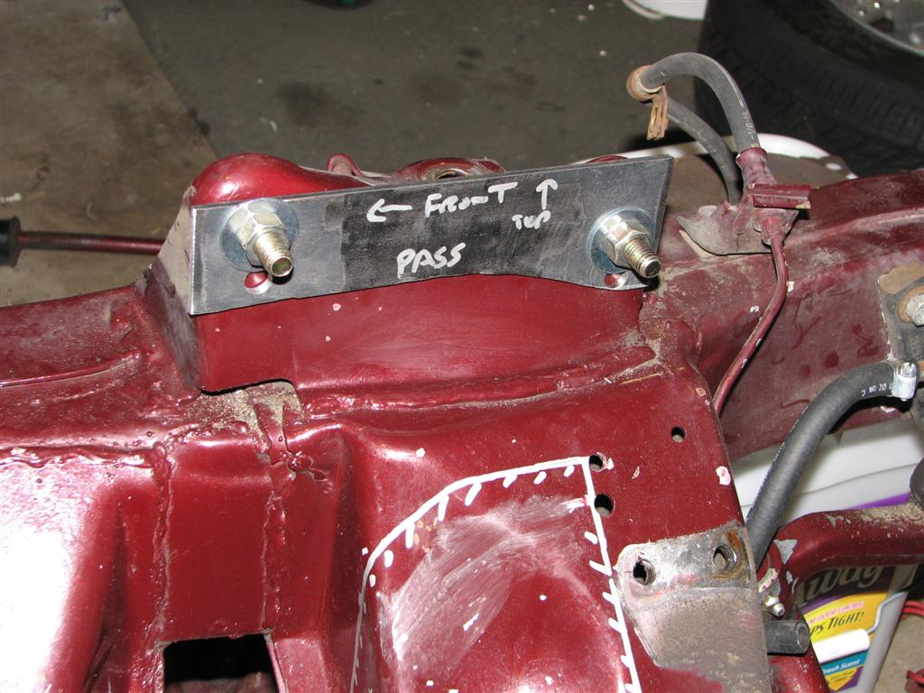
It looks like you're going all the way with custom engine mounts. I think you'll have good success. I took a photo for you at the end of my thread of the clearance between the plug wires and the booster.
Keep up the nice work.
It looks like you're going all the way with custom engine mounts. I think you'll have good success. I took a photo for you at the end of my thread of the clearance between the plug wires and the booster.
Keep up the nice work.
Thread Starter
Joined: Apr 2010
Posts: 2,816
Likes: 86
From: Instagram @chevyhotrodder
futureuser - I have done a lot of reading on the subject and I feel the g-mod will make a good budget-oriented improvement. If you look at the pictures of my car at autocross at the beginning of this thread, you can see the camber is positive on the outside tire - not what you want for good handling. If I were you, I would consider adding the holes to yours. Since you're using aftermarket arms, you can leave the original holes intact and go back if you want. Do some reading; it's just a matter of drilling some holes if you go the traditional route.
Last night I unbolted the motor mount plates and observed a definite movement of the UCA hole locations. So I removed the jig and then reinstalled it by just bolting it at the motor mounts (no bolts at the UCA towers). Doing this, the UCA hole locations fell right back into place. There is definitely some stress left in the jig from welding, but having it bolted down at the motor mounts puts it in the correct position. I think I am good to go.
Last night I unbolted the motor mount plates and observed a definite movement of the UCA hole locations. So I removed the jig and then reinstalled it by just bolting it at the motor mounts (no bolts at the UCA towers). Doing this, the UCA hole locations fell right back into place. There is definitely some stress left in the jig from welding, but having it bolted down at the motor mounts puts it in the correct position. I think I am good to go.

Thread Starter
Joined: Apr 2010
Posts: 2,816
Likes: 86
From: Instagram @chevyhotrodder
It will be the same color. 1970 Chevrolet Black Cherry - the original color of the car. I painted the frame ten years ago using PPG Delstar. I will just be dusting over it this round to cover the modified areas and fill in some of the scratches. The paint on the front crossmember especially has been through a lot. This isn't going to be a show car!
Here is a picture from Aug 2000 with the then-fresh paint:
And here's a before and after, also both from 2000. I was in high school when I did this originally. Lots of elbow grease to make it look nice, but these days I care less about show and more about go
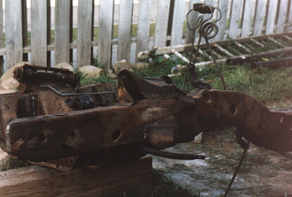

Here is a picture from Aug 2000 with the then-fresh paint:
And here's a before and after, also both from 2000. I was in high school when I did this originally. Lots of elbow grease to make it look nice, but these days I care less about show and more about go
Thread Starter
Joined: Apr 2010
Posts: 2,816
Likes: 86
From: Instagram @chevyhotrodder
Work continues on the Guldstrand mod. The next step was marking where to cut.


Then I used the angle grinder and cutoff wheel to cut off the tower.


It took quite a bit of cutting and grinding to get the remnants of bracketry off the frame. Once the frame was flat and clean of the old stuff, I went to work carefully trimming the tower until the holes lined up with my jig.


I have one problem area in near the back of the tower in this photo. You can see in that area there is a gap with the frame. The crossmember has a piece that overlaps and is welded onto the frame channels. I cut so it would line up with the top of that surface. Unfortunately it didn't extend far enough so that after the trimming, the UCA tower no longer intersects it. The gap is about 1/8" and I will probably fill it with weld before tacking the tower back in for final welding.

My next problem will be trimming the shock tower area in a way that doesn't move the upper shock mounting position. That will be fun!
Then I used the angle grinder and cutoff wheel to cut off the tower.
It took quite a bit of cutting and grinding to get the remnants of bracketry off the frame. Once the frame was flat and clean of the old stuff, I went to work carefully trimming the tower until the holes lined up with my jig.
I have one problem area in near the back of the tower in this photo. You can see in that area there is a gap with the frame. The crossmember has a piece that overlaps and is welded onto the frame channels. I cut so it would line up with the top of that surface. Unfortunately it didn't extend far enough so that after the trimming, the UCA tower no longer intersects it. The gap is about 1/8" and I will probably fill it with weld before tacking the tower back in for final welding.
My next problem will be trimming the shock tower area in a way that doesn't move the upper shock mounting position. That will be fun!
Thread Starter
Joined: Apr 2010
Posts: 2,816
Likes: 86
From: Instagram @chevyhotrodder
Got a little time to work on this. The next job was reforming the shock mounting plate area to meet up with the trimmed UCA tower.
I started by making a pie-cut here:

Next, I inserted a long piece of 1-1/2" square tube under the shock mount hole as a lever so I could prevent it from bending down. Then I used a large adjustable wrench that I moved along the edge and little by little bent the metal downward until it matched up with the edge of the control arm tower, all the while holding the shock mount hole area up using that square tube. This worked well and I was able to keep the bend roughly at the edge of the adjustable wrench without the shock mount hole moving anywhere.

I had to also trim the edge that met with the UCA tower using a cutoff wheel. I trimmed a bit much and my pie cut was a little larger than necessary, but I think the gaps are manageable. It should work out great once it's welded up.

I started by making a pie-cut here:
Next, I inserted a long piece of 1-1/2" square tube under the shock mount hole as a lever so I could prevent it from bending down. Then I used a large adjustable wrench that I moved along the edge and little by little bent the metal downward until it matched up with the edge of the control arm tower, all the while holding the shock mount hole area up using that square tube. This worked well and I was able to keep the bend roughly at the edge of the adjustable wrench without the shock mount hole moving anywhere.
I had to also trim the edge that met with the UCA tower using a cutoff wheel. I trimmed a bit much and my pie cut was a little larger than necessary, but I think the gaps are manageable. It should work out great once it's welded up.
futureuser - I have done a lot of reading on the subject and I feel the g-mod will make a good budget-oriented improvement. If you look at the pictures of my car at autocross at the beginning of this thread, you can see the camber is positive on the outside tire - not what you want for good handling. If I were you, I would consider adding the holes to yours. Since you're using aftermarket arms, you can leave the original holes intact and go back if you want. Do some reading; it's just a matter of drilling some holes if you go the traditional route.
Keep up the good work on your subframe. Clearly, you are going to have something clean and unique when done.
Last edited by futureuser; May 7, 2011 at 09:12 AM.

TECH Resident

Joined: Aug 2002
Posts: 909
Likes: 2
From: La.
My understanding is that most of the aftermarket arms have corrections built in. I don't know which design the ebay arms copied, but I plan to have a specialist check it on an alignment rack.
Keep up the good work on your subframe. Clearly, you are going to have something clean and unique when done.
Keep up the good work on your subframe. Clearly, you are going to have something clean and unique when done.

Thread Starter
Joined: Apr 2010
Posts: 2,816
Likes: 86
From: Instagram @chevyhotrodder
Aftermarket arms do make changes in geometry, but they generally do not produce as dramatic of an effect on the bump/rebound camber curve as what I'm doing with the g-mod. The bigger change for the aftermarket upper arms is moving the upper ball joint rearward to increase caster. In addition to steering feedback, the increased caster will cause camber gain during a turn because the wheel tilts with the steering angle. At sharp steering angles, this becomes significant and is advantageous for autocross events where you have lots of tight turns. But it doesn't help so much with low steering angles where the caster does not come (as much) into play - for example, on a fast wide sweeping turn. This is where the g-mod should help because g-forces will result in body roll which will now produce favorable camber.
Suspension geometry is a balancing act often with tradeoffs. Many components come into play, so I hesitate to make the following broad stroked assertion like the g-mod will always help in all situations. But from what I have researched I feel it is an appropriate modification for the driving I'll be doing. I hope to eventually add aftermarket arms which I feel will further help.
Suspension geometry is a balancing act often with tradeoffs. Many components come into play, so I hesitate to make the following broad stroked assertion like the g-mod will always help in all situations. But from what I have researched I feel it is an appropriate modification for the driving I'll be doing. I hope to eventually add aftermarket arms which I feel will further help.
Thread Starter
Joined: Apr 2010
Posts: 2,816
Likes: 86
From: Instagram @chevyhotrodder
After finishing up all the trim & prep work, it was time to weld things up. I started by installing the jig and bolting everything in solid.

Next I tacked everything in place - four corners betwen the tower and frame and two tacks between the shock mount and tower. Then I got busy welding in approximatelly four inch sections welding the ends first, then the center. I am embarrased of the welds here: they're a bit on the cold side and my starts & stops are obvious. I haven't welded in a long time and this is the first project I've really put my new MM180 to work. Hopefully these will get the job done.


The pie cut was welded and ground flat followed by some flapper wheel to blend everything. I then cleaned up the edge with a cutoff wheel. You'd hardly know it was cut at all.


Next I bolted on the upper control arm and discovered this common area for interferance.


To gain the needed clearance, I notched and ground a small portion of the arm until it would bolt on and move through the expected range of travel. Here you can see the notched passenger arm next to the yet unmodified driver arm.

That's all for now. The other side should go faster now that I think I know what I'm doing.
Next I tacked everything in place - four corners betwen the tower and frame and two tacks between the shock mount and tower. Then I got busy welding in approximatelly four inch sections welding the ends first, then the center. I am embarrased of the welds here: they're a bit on the cold side and my starts & stops are obvious. I haven't welded in a long time and this is the first project I've really put my new MM180 to work. Hopefully these will get the job done.
The pie cut was welded and ground flat followed by some flapper wheel to blend everything. I then cleaned up the edge with a cutoff wheel. You'd hardly know it was cut at all.
Next I bolted on the upper control arm and discovered this common area for interferance.
To gain the needed clearance, I notched and ground a small portion of the arm until it would bolt on and move through the expected range of travel. Here you can see the notched passenger arm next to the yet unmodified driver arm.
That's all for now. The other side should go faster now that I think I know what I'm doing.

Looks good! I think your welds are fine. MM180 is that a Millermatic 180? I have the cousin a Hobart 175. Good welders and heavy enough to get the job done but light enough for thin metal as well. Enough with the suspension lets see this thing roll on its own power. When your done come on over and get mine going for me as I am dragging tail to get it done.
Your work looks great to me! Of course, coming from me that could be more of an insult than a compliment
Thanks for the info on the control arms. I'm going to get my car aligned Monday, and see how it goes.
Thanks for the info on the control arms. I'm going to get my car aligned Monday, and see how it goes.

Launching!
Joined: Jan 2011
Posts: 200
Likes: 0
From: Arizona
bandit- thank you for all of the pics. i have had the g-mod template in the shop for a while and thought about everyway possible to do it, but you made it look simple. i will be using your idea soon.
thanks
-wade-
thanks
-wade-