

67 Chevelle LS1 T56 Build
 05-22-2012, 08:40 AM
#41
TECH Enthusiast

I'm pretty sure I mounted the tanks inc setup toward the drivers side at the flat spot toward the front of the car , still had to flatten out that area some and had to cut the kit as short as possible . look through my thread to see it . JOHN
 05-26-2012, 12:53 PM
#42
Staging Lane
Thread Starter

Join Date: Dec 2007
Posts: 85
Likes: 0
Received 0 Likes
on
0 Posts

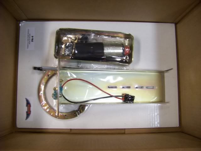
Well, the fuel tank goodies showed up this week, so I had the tank boiled at the local radiator shop and today and I am going to install the pump. I I have decided to locate it on the passenger side front of the tank. Main reason is that I tend to make the harder turns to the left, so the fuel will push to the right side of the car.
Also, mocked up my front suspension components. Still looking for your opinions on my brakes. I have been talking to Matt at MCB and he is pricing out a Baer T4/SS4 system and a Wilwood master along with all the hard lines and proportioning valve. Anyone have other thoughts on brakes? I want to get this thing on the autocross, so I am also reconsidering the Coddington wheels and looking for opinions on wheels?

Also, mocked up my front suspension components. Still looking for your opinions on my brakes. I have been talking to Matt at MCB and he is pricing out a Baer T4/SS4 system and a Wilwood master along with all the hard lines and proportioning valve. Anyone have other thoughts on brakes? I want to get this thing on the autocross, so I am also reconsidering the Coddington wheels and looking for opinions on wheels?
05-26-2012, 11:16 PM
#44
Staging Lane
Thread Starter
Join Date: Dec 2007
Posts: 85
Likes: 0
Received 0 Likes
on
0 Posts
05-26-2012, 11:35 PM
#45
Staging Lane
Thread Starter
Join Date: Dec 2007
Posts: 85
Likes: 0
Received 0 Likes
on
0 Posts
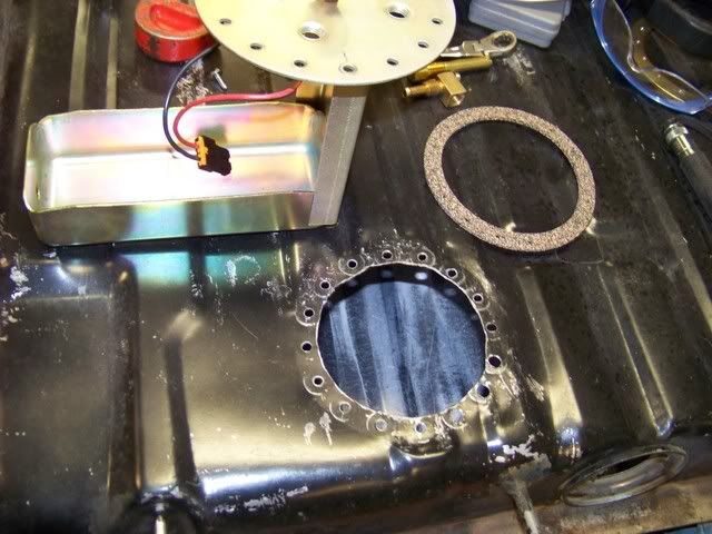
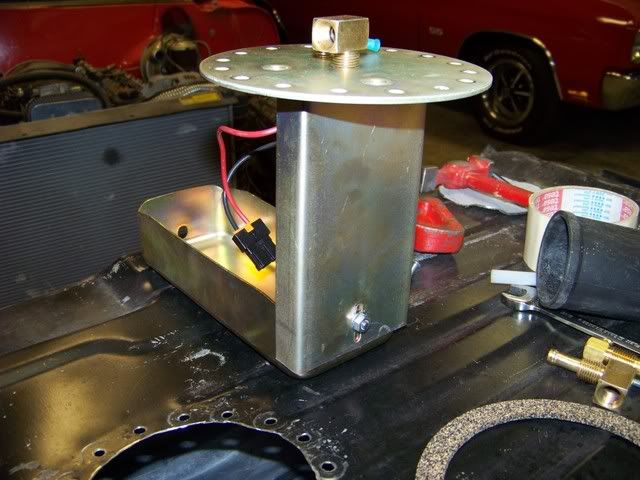
Well, I finished the Pump install. Took me about twice as long because I put the tank up and just kept measuring over and over again. The big concerns that I had were the following:
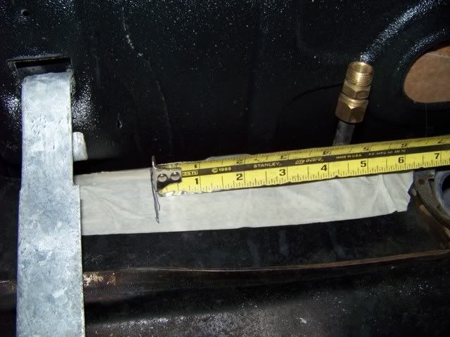
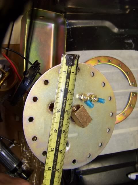
Below - Notice that the fittings do not start until about 2.5" from the edge of the plate. This allowed me to push the plate more to the side because there would not be interference with the trunk brace, only the thickness of the flange and the heads of the attachment screws. The fittings are the main clearance issue.
Below - Hole is cut out and holes drilled for screws. I did have to use a 3" cutoff wheel to deburr the holes.
Have the pump and tray height set so that the tray sits on the floor of the tank.
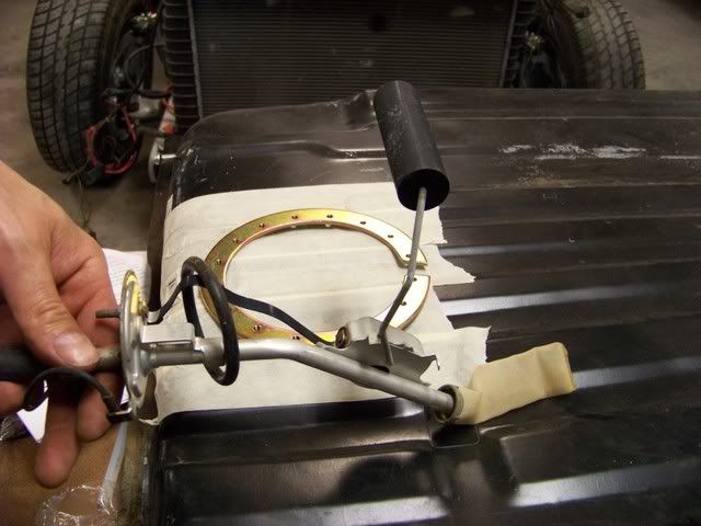
Below - Float will clear.
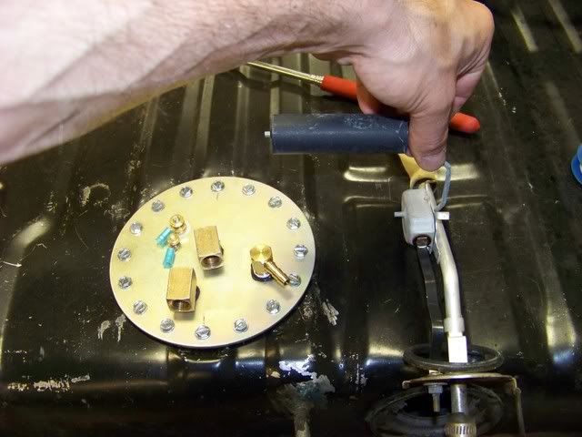
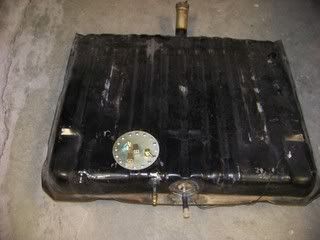
Below - And at last here it is. Now to buy some fittings and fuel line.
- Had to keep the fittings clear of the trunk floor brace so that I won't have to shim the front of the tank down quite so far.
- Had to keep the pump far enough to the side so that it did not interfer with the sending unit float. The float would interfere with the vertical support with a full tank of gas.
- As I worked the metal of the tank to try and get the hole opening flat, I kept pushing metal around due to the stamped ribs. I never could get the surface perfectly flat, but once the ring is in there, everything pulls up tight.
Below - Notice that the fittings do not start until about 2.5" from the edge of the plate. This allowed me to push the plate more to the side because there would not be interference with the trunk brace, only the thickness of the flange and the heads of the attachment screws. The fittings are the main clearance issue.
Below - Hole is cut out and holes drilled for screws. I did have to use a 3" cutoff wheel to deburr the holes.
Have the pump and tray height set so that the tray sits on the floor of the tank.
Below - Float will clear.
Below - And at last here it is. Now to buy some fittings and fuel line.
Last edited by Rucumn; 05-26-2012 at 11:41 PM.
06-01-2012, 12:38 PM
#46
Staging Lane
Thread Starter
Join Date: Dec 2007
Posts: 85
Likes: 0
Received 0 Likes
on
0 Posts
Alright, I have the fuel rails with the built in regulator, meaning that it has two ports. Trying to decide if I should convert to the single port rails and then run the corvette filter/regulator so that I have only 1 line running up to the engine bay?
Any suggestions?
Any suggestions?
06-03-2012, 10:27 PM
#47
Staging Lane
Thread Starter
Join Date: Dec 2007
Posts: 85
Likes: 0
Received 0 Likes
on
0 Posts
Not much forward progress this weekend although I spent a fair amount of time working on the set up. Put about 3 hours into measuring and fabbing up a tranny crossmember. I will post some pics when I am done with it. Since this new frame is all boxed in, I didn't really want to cut up the factory crossmember, so I just took some 1.5 inch square tubing and a piece of angle iron and it looks like it clears the exhaust. Pics to come.
Anyway, I spent most of the time trying to set the angle of the engine and tranny to within -3 degrees or less. When I bought the car, the guy sold it to me running and driving, but he clearly stated that it needed some additional work to make it right. Well, I checked the angle where he had it set and it was at -6 degrees! Here I thought the vibrations I would feel around 60 mph were from a poorly aligned front end.
Anyway, I spent most of the time trying to set the angle of the engine and tranny to within -3 degrees or less. When I bought the car, the guy sold it to me running and driving, but he clearly stated that it needed some additional work to make it right. Well, I checked the angle where he had it set and it was at -6 degrees! Here I thought the vibrations I would feel around 60 mph were from a poorly aligned front end.
06-03-2012, 10:35 PM
#48
Staging Lane
Thread Starter
Join Date: Dec 2007
Posts: 85
Likes: 0
Received 0 Likes
on
0 Posts
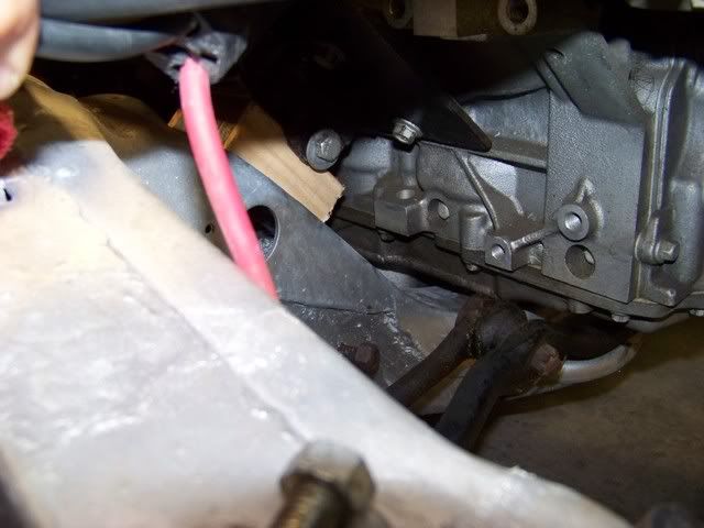
Well, I couldn't jack the tranny up anymore because it was already only a fraction of an inch from touching the floors, so I decided that I needed to try and lower the engine. I had tall mounts, which were about 2-1/4" off of the frame and the pan had a lot of clearance with the crossmember. So, I started by just putting the bolts through the engine mounts and then setting the engine down on some short pieces of 2x3, giving me the effect of about a 1-11/16" mount stand. This dropped the pan down considerably.
With Tall Mounts
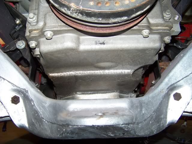
Mocked up with shorter mounting
With Tall Mounts
Mocked up with shorter mounting
06-03-2012, 10:41 PM
#49
Staging Lane
Thread Starter
Join Date: Dec 2007
Posts: 85
Likes: 0
Received 0 Likes
on
0 Posts
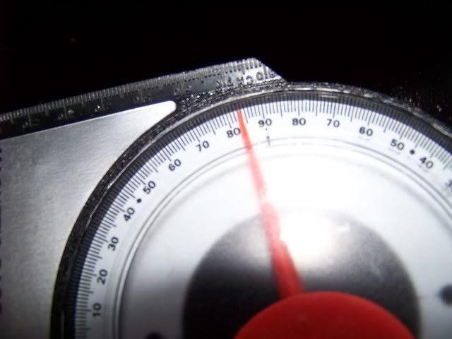
Mounting it lower, I was able to get my tranny angle to -2 degrees, but the tranny was hitting the tunnel in a few spots. Not a big deal because I was planning to just use the porta-power to make some room in those spots.
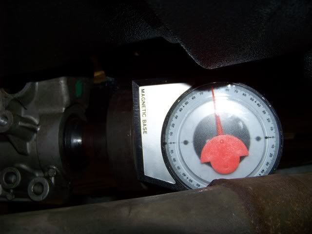
Angle measured on the machined surface of the block by the starter motor mount. Angle finder is pointed forward, so shows positive angle, but it is actually a negative angle back to the rear of the car.
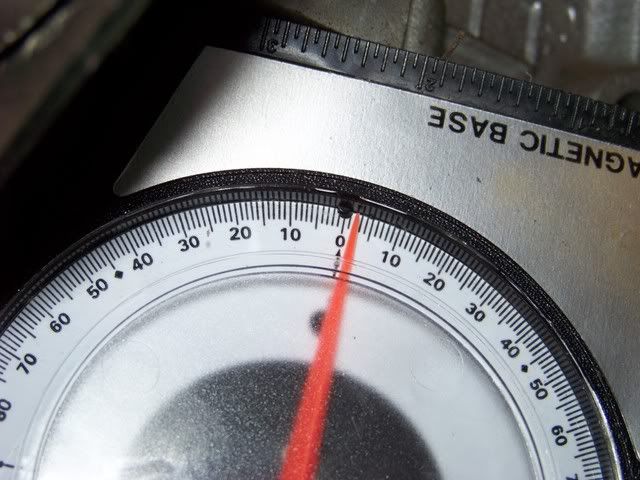
Angle measured on the machined surface of the block by the starter motor mount. Angle finder is pointed forward, so shows positive angle, but it is actually a negative angle back to the rear of the car.
Last edited by Rucumn; 06-03-2012 at 11:01 PM. Reason: Resize pics
06-03-2012, 11:06 PM
#50
Staging Lane
Thread Starter
Join Date: Dec 2007
Posts: 85
Likes: 0
Received 0 Likes
on
0 Posts
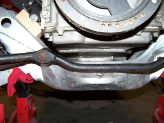
Well, just when I thought I had it made, I found another problem that most have encountered during their builds. The tie rod hit the pan on the passenger side! CRAP!!!!
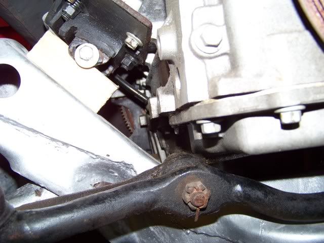
Drivers side cleared because of the nice little cast indentation on this side of the pan.
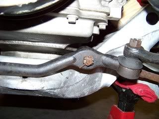
Drivers side cleared because of the nice little cast indentation on this side of the pan.
06-04-2012, 06:31 PM
#51
Staging Lane
Thread Starter
Join Date: Dec 2007
Posts: 85
Likes: 0
Received 0 Likes
on
0 Posts
I wanted to see just how far into the turn I was when the passenger inner tie rod hit the pan, so I first marked center, then turned to full lock toward the right where I know I have full clearance. You can see that the center link travels just at 3 inches to the right.
Next, I turned as far as I could to the left until the inner tie rod on the passenger side hit the pan. It hits around 2-1/4 inches, so I am losing about 3/4 inches of travel.
Next, I turned as far as I could to the left until the inner tie rod on the passenger side hit the pan. It hits around 2-1/4 inches, so I am losing about 3/4 inches of travel.
06-04-2012, 06:40 PM
#52
Staging Lane
Thread Starter
Join Date: Dec 2007
Posts: 85
Likes: 0
Received 0 Likes
on
0 Posts
My goal is still to run the factory 4 speed console in the car, but I am thinking that I have no choice but to abandon the stock tunnel goal.
I have looked up a few ways to deal with the tunnel and I think I have found my method. On the chevelles.com site, there is a good post on tunnel mods and I will be following this method. Just need to figure how little of lift I can get away with and also make sure the console still fits ok.
Images of stealth71 on chevelles.com
06-04-2012, 07:01 PM
#53
TECH Apprentice

This is what it takes to clear f-Body pan on my 67 skylark, I'm runing 4L85E, the RH just slides by the pan. Good luck I have several hours and a few pounds of scrap metal to get to this point.
 06-05-2012, 10:47 AM
#55
On The Tree
iTrader: (2)

Join Date: Jun 2011
Location: Nashville, TN
Posts: 170
Likes: 0
Received 0 Likes
on
0 Posts
I tried very hard to not have to cut my transmission tunnel during my swap. When I finally decided I needed to do it, I cut lengthwise up the center of the tunnel and then two cross cuts on either end. The tunnel only needed to open up in a v-pattern to clear the trans. At the back (the widest opening), it was roughly 2-3" spread.
My build page is not updated yet. Hopefully I can get it updated sometime this week. But, I would really recommend trying it this way instead of chopping out the whole tunnel. It was very easy.
Either way, good luck!
Troy
My build page is not updated yet. Hopefully I can get it updated sometime this week. But, I would really recommend trying it this way instead of chopping out the whole tunnel. It was very easy.
Either way, good luck!
Troy
06-05-2012, 12:18 PM
#56
Staging Lane
Thread Starter
Join Date: Dec 2007
Posts: 85
Likes: 0
Received 0 Likes
on
0 Posts
I tried very hard to not have to cut my transmission tunnel during my swap. When I finally decided I needed to do it, I cut lengthwise up the center of the tunnel and then two cross cuts on either end. The tunnel only needed to open up in a v-pattern to clear the trans. At the back (the widest opening), it was roughly 2-3" spread.
My build page is not updated yet. Hopefully I can get it updated sometime this week. But, I would really recommend trying it this way instead of chopping out the whole tunnel. It was very easy.
Either way, good luck!
Troy
My build page is not updated yet. Hopefully I can get it updated sometime this week. But, I would really recommend trying it this way instead of chopping out the whole tunnel. It was very easy.
Either way, good luck!
Troy
Thanks for the advice.
 06-05-2012, 10:24 PM
#58
Staging Lane
Thread Starter
Join Date: Dec 2007
Posts: 85
Likes: 0
Received 0 Likes
on
0 Posts
That was the original plan, but there is just too much metal that has to move and it needs to come from somewhere.
And I don't need lessons on BFH body work. I have actually graduated to the kinder and gentler methods such as using a porta-power - much better results.
Vette_IA.... are you sure this isn't "Used-to-have-a-Vette_IA"? I'm just taking a guess based on your recent sign up status and your location (Ryan?).
07-08-2012, 10:09 PM
#60
Staging Lane
Thread Starter
Join Date: Dec 2007
Posts: 85
Likes: 0
Received 0 Likes
on
0 Posts
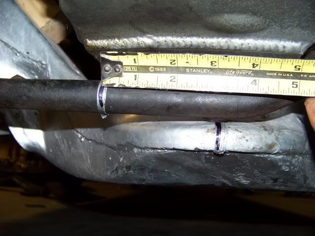
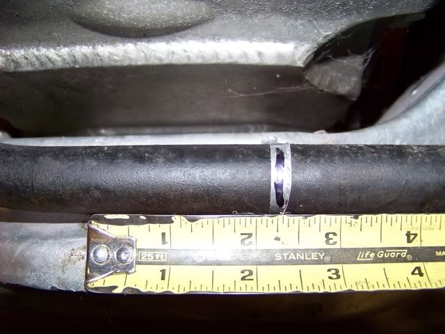
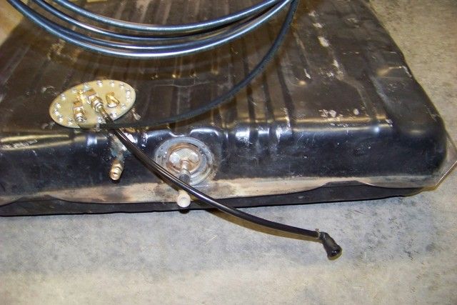
It's been over a month, but I have made a little progress. I had a lot of head scratching moments trying to figure out the fuel lines. My car has the earlier LS1 pressure regulating rail, so I needed to run a return line the length of the car along with the feed line. After hours of research and reading about the degradation of braided hose and trying to figure out the cost of about 35 fittings for a hybrid hard and flex hose set up, I finally came across BrakeQuip. After speaking to one of their technicians, he sold me on using their product as it is a close match to OEM and it won't deteriorate with time. On BrakeQuip's website, I was able to find a distributor of their products close to me, so I brought my tank to them after I took some measurements and they had me fixed up in a few days! The cost was just under $200 with new filter and all fittings to screw into the Tanks Inc pump. I still need to figure out what mounting clips I am going to use.
Feed Line
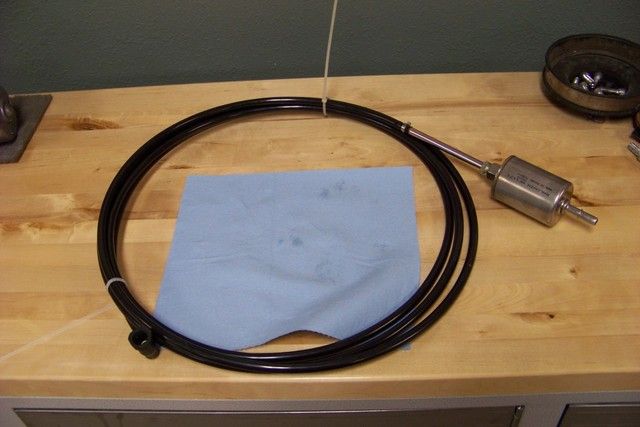
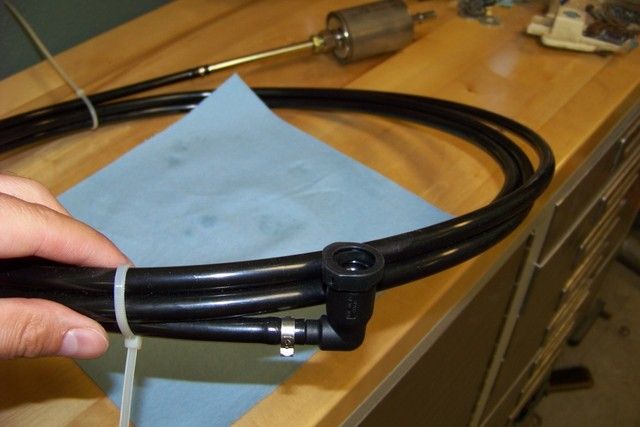
Feed Line