
88 Fiero Formula LS4/F40 6 speed swap
 11-15-2023, 04:32 PM
#501
This is my favorite conversion thread on the forum, and that is a testament to your determination to solve every problem thrown in your way and not conforming to the norms. That's saying alot considering I have a number of build threads of my own here.

The following 5 users liked this post by LSswap:
2001 5.3 formula (07-20-2024), bobcratch (11-15-2023), G Atsma (11-15-2023), ryeguy2006a (11-17-2023), Zanie (11-16-2023)
11-18-2023, 06:42 AM
#502
Registered User

Join Date: Nov 2023
Posts: 1
Likes: 0
Received 0 Likes
on
0 Posts
I have been working on this swap off and on for nearly 2 years, but it is finally getting close to being finished.
The LS4 is the bastard child of the LS(x) family with a restrictive intake and a 303hp rating, no starter provision on the block and the GM Metric bellhousing pattern (not the SBC/LS1 bolt pattern). It was designed for a transverse layout and has the shortest overall length, which is good for fitting it between the Fiero frame rails. It also bolts directly to the F40 6 speed manual transmission from the 2006+ Pontiac G6.
Since my mild SBC/getrag swap (in another 88 Fiero) put 282 hp to the wheels, I want this swap to have 50+ more whp. The more the better. So the stock 303 hp just wont get it done, and there will be several basic upgrades to raise the HP along the way.
The build plan:
*Upgrade to an 85mm MAF, LS2 DBW throttlebody, Intake, Fuel Rail and Injectors.
* Upgrade to a DoD compatible 224/232 .564/.575 @ 113 lsa
* Upgrade to LS7 hydro formed exhaust manifolds
* Custom 12# aluminum flywheel designed for the LS4/F40 application
* 10" Spec Stage 4+ clutch
* Retain DoD function... not sure if I will be able to get it to work, but going to give it a shot.
* Tuck 10 1/2" wheels under the stock body in the rear.
* 13" brake upgrade
* Several other suspension upgrades to improve handling performance.
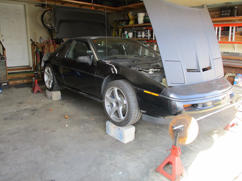
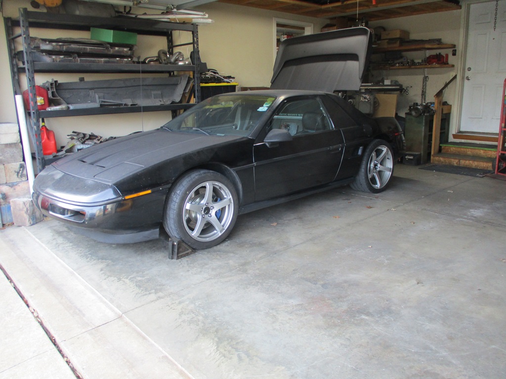
Here is the lucky recipient, but it will end up being painted to get rid of the yellow racing stripes, and will probably blue like the GT behind it (my retired SBC car).
Attachment 611831
The engine is a 2007 LS4 with 17K miles on it:
http://i152.photobucket.com/albums/s...ru/LS4/034.jpg
I will be making additional posts with lots of pictures/details of the swap, so stay tuned.
The LS4 is the bastard child of the LS(x) family with a restrictive intake and a 303hp rating, no starter provision on the block and the GM Metric bellhousing pattern (not the SBC/LS1 bolt pattern). It was designed for a transverse layout and has the shortest overall length, which is good for fitting it between the Fiero frame rails. It also bolts directly to the F40 6 speed manual transmission from the 2006+ Pontiac G6.
Since my mild SBC/getrag swap (in another 88 Fiero) put 282 hp to the wheels, I want this swap to have 50+ more whp. The more the better. So the stock 303 hp just wont get it done, and there will be several basic upgrades to raise the HP along the way.
The build plan:
*Upgrade to an 85mm MAF, LS2 DBW throttlebody, Intake, Fuel Rail and Injectors.
* Upgrade to a DoD compatible 224/232 .564/.575 @ 113 lsa
* Upgrade to LS7 hydro formed exhaust manifolds
* Custom 12# aluminum flywheel designed for the LS4/F40 application
* 10" Spec Stage 4+ clutch
* Retain DoD function... not sure if I will be able to get it to work, but going to give it a shot.
* Tuck 10 1/2" wheels under the stock body in the rear.
* 13" brake upgrade
* Several other suspension upgrades to improve handling performance.
Here is the lucky recipient, but it will end up being painted to get rid of the yellow racing stripes, and will probably blue like the GT behind it (my retired SBC car).
Attachment 611831
The engine is a 2007 LS4 with 17K miles on it:
http://i152.photobucket.com/albums/s...ru/LS4/034.jpg
I will be making additional posts with lots of pictures/details of the swap, so stay tuned.


The following users liked this post:
G Atsma (11-18-2023)
01-21-2024, 06:58 PM
#504
The Fiero has been hibernating with the colder temps but I have been slowly working on small things with it.
Fixed a leak on the oil drain line.
Installed a smart rear view mirror with forward and backup cameras.
Installed the 8 psi wastegate spring - was running an 8 psi one that had been cut about 40% shorter to help keep it out of boost while tuning the NA portions of the maps.
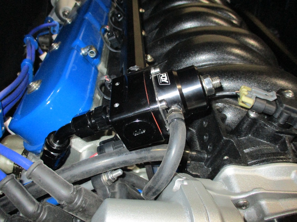
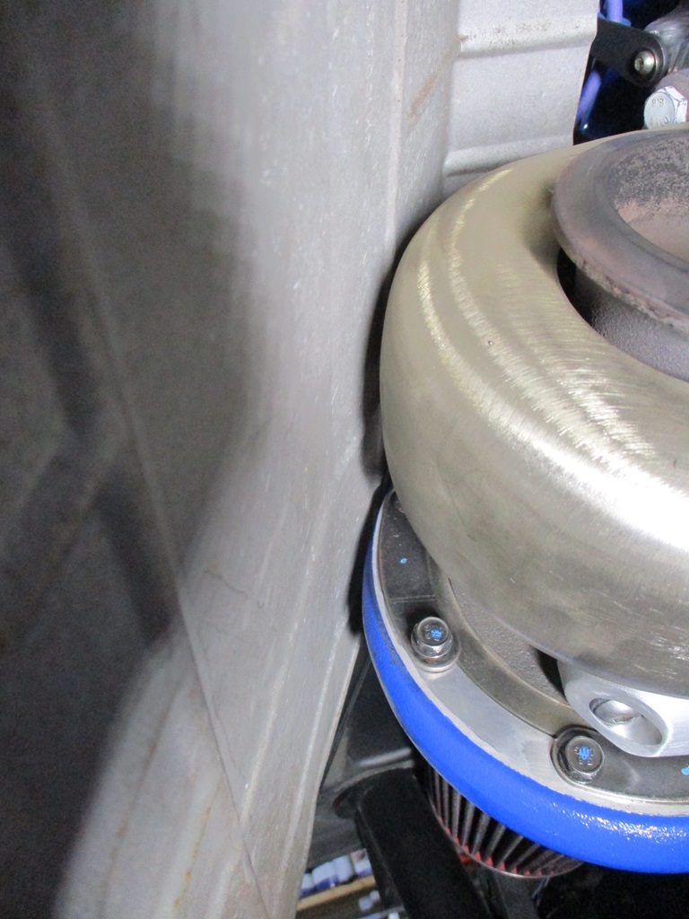
Took off the fuel pressure regulator so it could be flipped around so the pressure sensor would be on the bottom and hidden. This is much better:
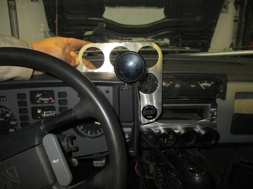
Replaced the 1/4" boost sense lines, and ran three 1/4" poly lines into the interior so a manual boost ****. The original plan was to mount some gauges like this and have the boost **** as part of the assembly (but it would block visibility and access to the radio/gps unit that is going where the OEM volt and oil pressure gauges are). I have some thoughts on how to address, but need to make some mock up parts to verify.
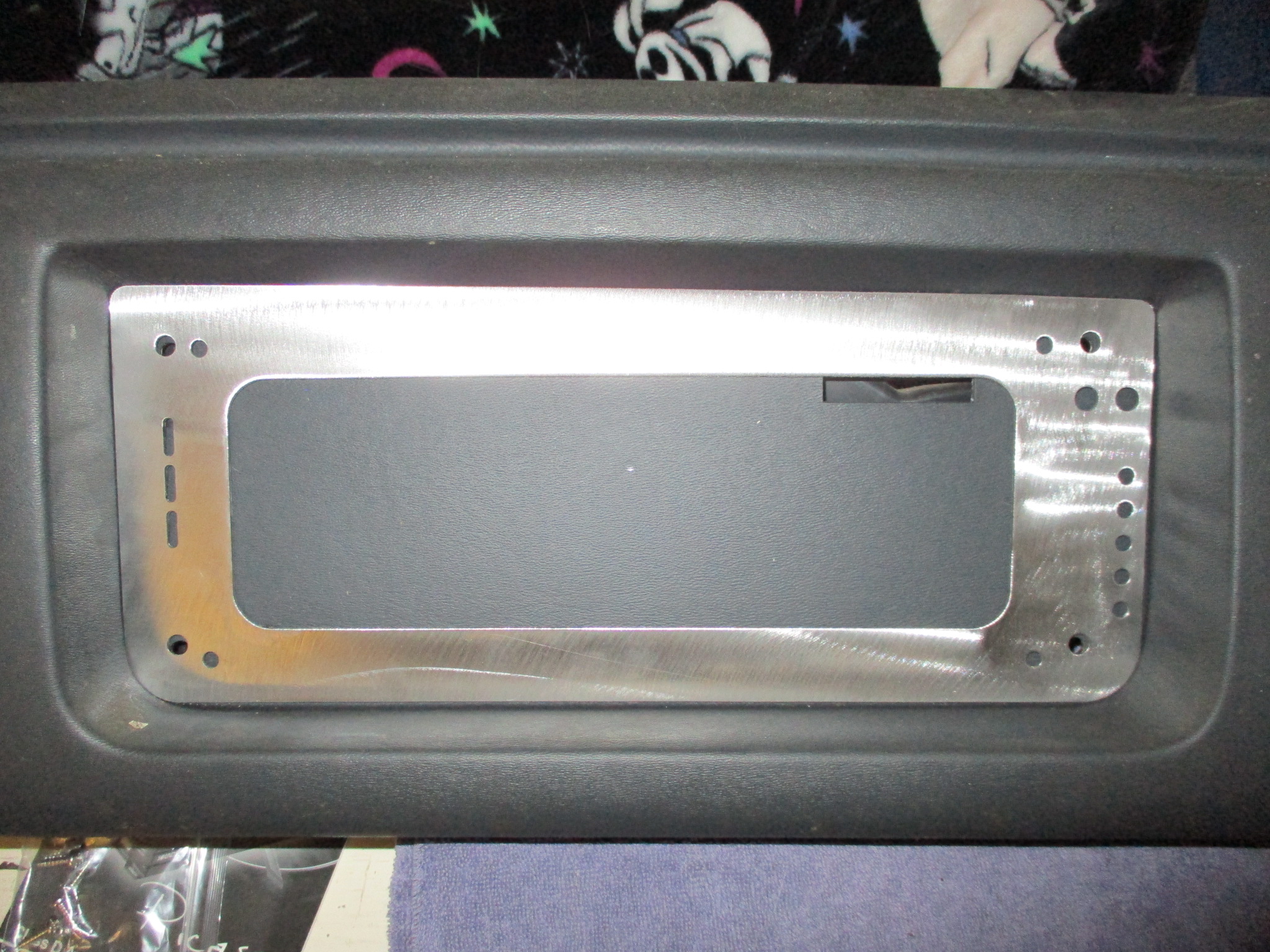
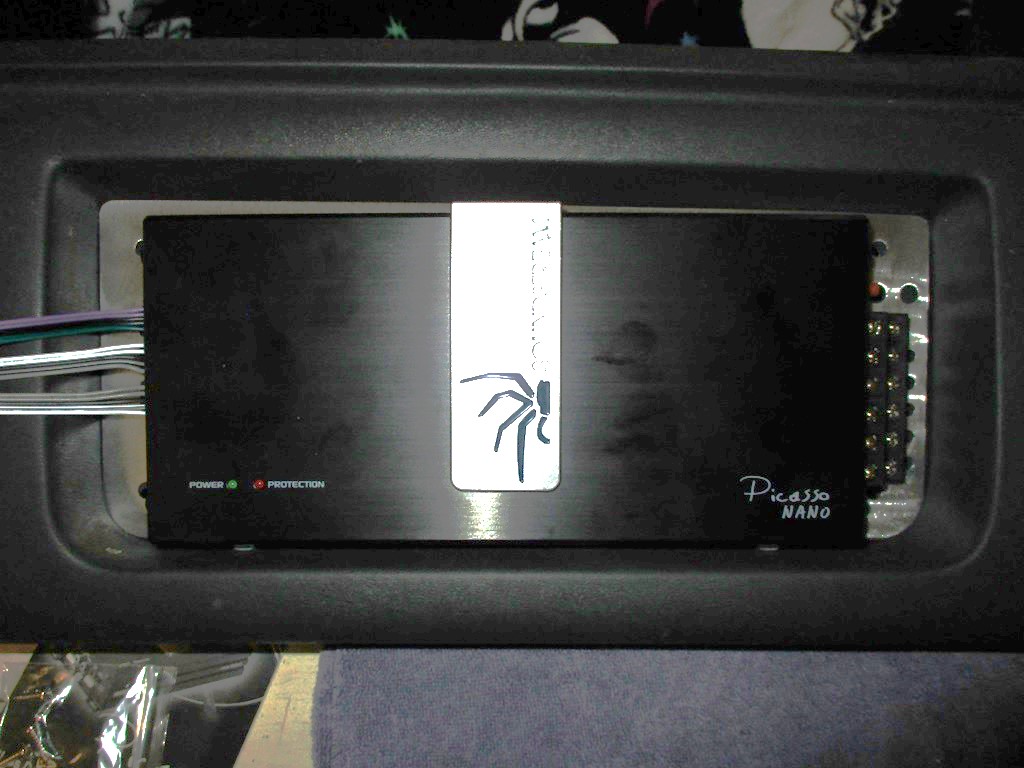
Shifted focus to making a mount plate for the amplifier. This is pretty close to final. Still pondering the use of a cover ring around the amp and to the dash to keep all the wires hidden:
Installed the OEM heat shield between the turbo and the trunk. It has about 1/8" from the compressor as well as the stainless heat shield on the turbine.
For the holidays I made this sign for my families white elephant gift (with 3 brothers and their 3 son's, I figured one of them would like it, which they did... I still need to make one for me).
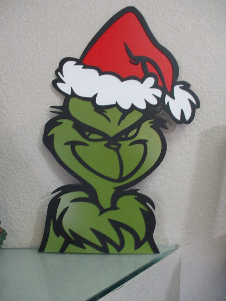
For my wife, I made her this to add to her Grinch collection. This one is 2 layers.
A week before Christmas, I fell off some stairs in the garage and severely sprained my ankle. So that slowed things down with my foot being in a boot, but this past week there was enough progress to upgrade to an ankle brace. Probably 80% better now, but at least I can wear my normal boots and get back to working on the Fiero.
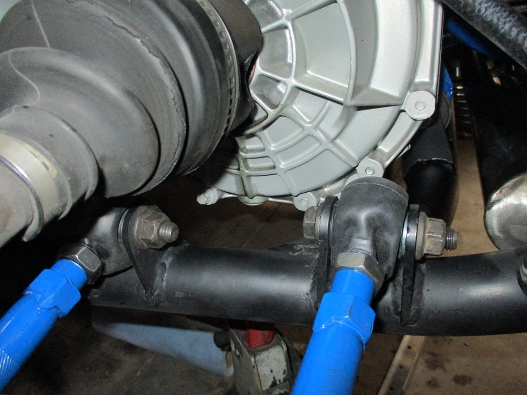
This weekend I worked on the lateral links and sway bar links.
I tried some new poly ends from Speedway motors earlier this year. They looked awesome, but the lateral links move to much front to rear as the suspension cycles, so they were binding and needed to be replaced before one snapped. At least 1 of them was bent when removed, so perfect timing. The driver side ones were pulled and rod ends put back in, but with a rubber boot this time. We will see if I they last more than 10K miles this time.
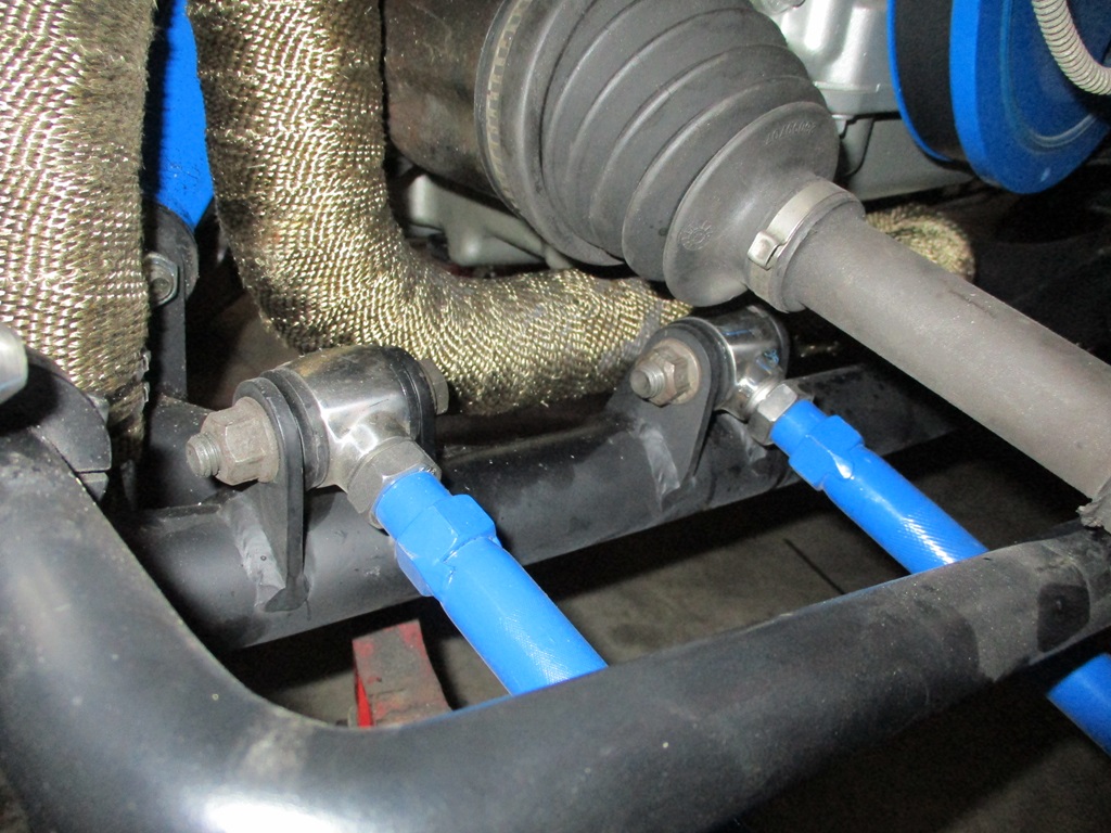
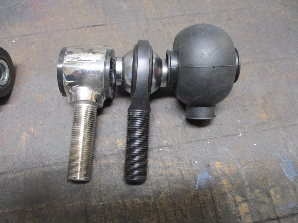
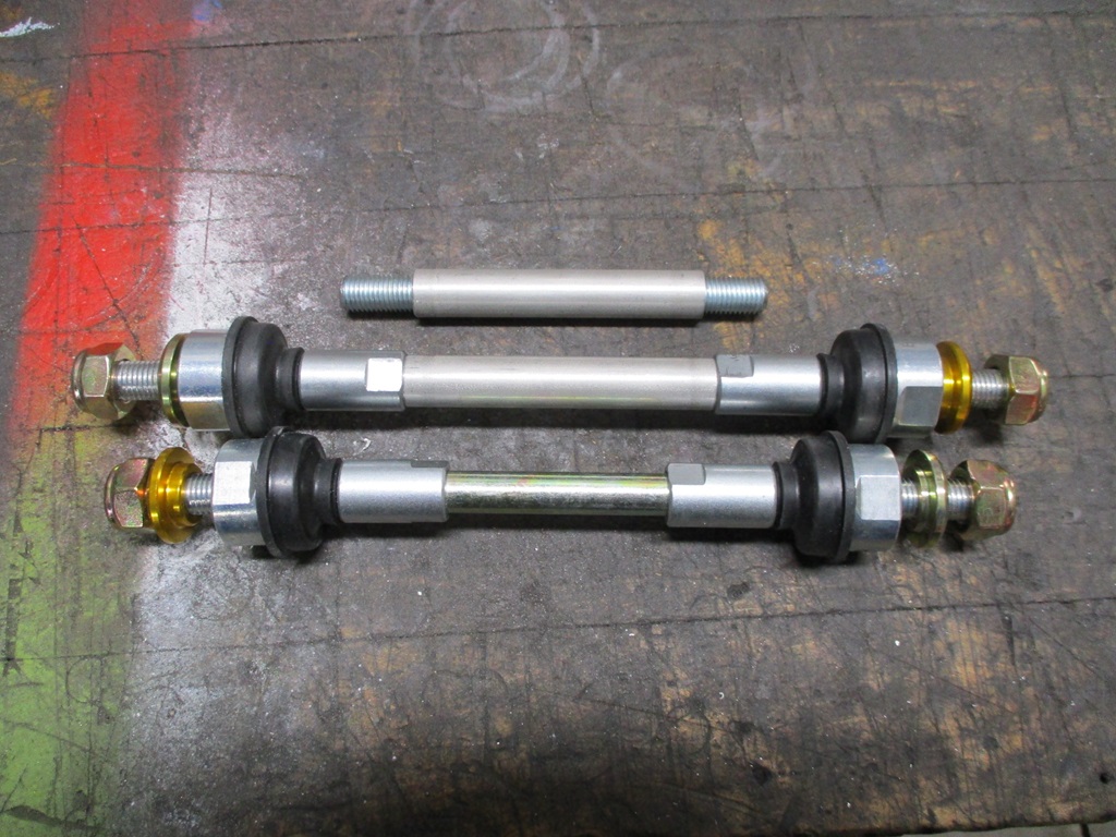
The zero-lash rod ends from the original swap are likely in a tote somewhere... They would have been too short anyway, so ordered the longest ones from Rodney. Once they arrived, they also were too short for the relocated sway bar, so took them apart and made them longer.
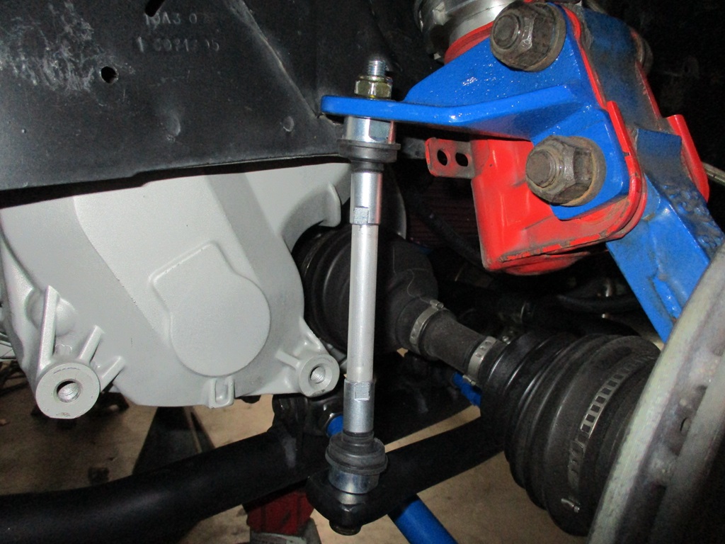
After Tuesday this week, the daily highs will be in the upper 40s and lower 50s for 2 weeks, so I would like to be done with the other side of the suspension by next weekend so I can take the Fiero out for some more turning runs.
Fixed a leak on the oil drain line.
Installed a smart rear view mirror with forward and backup cameras.
Installed the 8 psi wastegate spring - was running an 8 psi one that had been cut about 40% shorter to help keep it out of boost while tuning the NA portions of the maps.
Took off the fuel pressure regulator so it could be flipped around so the pressure sensor would be on the bottom and hidden. This is much better:
Replaced the 1/4" boost sense lines, and ran three 1/4" poly lines into the interior so a manual boost ****. The original plan was to mount some gauges like this and have the boost **** as part of the assembly (but it would block visibility and access to the radio/gps unit that is going where the OEM volt and oil pressure gauges are). I have some thoughts on how to address, but need to make some mock up parts to verify.
Shifted focus to making a mount plate for the amplifier. This is pretty close to final. Still pondering the use of a cover ring around the amp and to the dash to keep all the wires hidden:
Installed the OEM heat shield between the turbo and the trunk. It has about 1/8" from the compressor as well as the stainless heat shield on the turbine.
For the holidays I made this sign for my families white elephant gift (with 3 brothers and their 3 son's, I figured one of them would like it, which they did... I still need to make one for me).
For my wife, I made her this to add to her Grinch collection. This one is 2 layers.
A week before Christmas, I fell off some stairs in the garage and severely sprained my ankle. So that slowed things down with my foot being in a boot, but this past week there was enough progress to upgrade to an ankle brace. Probably 80% better now, but at least I can wear my normal boots and get back to working on the Fiero.
This weekend I worked on the lateral links and sway bar links.
I tried some new poly ends from Speedway motors earlier this year. They looked awesome, but the lateral links move to much front to rear as the suspension cycles, so they were binding and needed to be replaced before one snapped. At least 1 of them was bent when removed, so perfect timing. The driver side ones were pulled and rod ends put back in, but with a rubber boot this time. We will see if I they last more than 10K miles this time.
The zero-lash rod ends from the original swap are likely in a tote somewhere... They would have been too short anyway, so ordered the longest ones from Rodney. Once they arrived, they also were too short for the relocated sway bar, so took them apart and made them longer.
After Tuesday this week, the daily highs will be in the upper 40s and lower 50s for 2 weeks, so I would like to be done with the other side of the suspension by next weekend so I can take the Fiero out for some more turning runs.
The following 3 users liked this post by fieroguru:
01-23-2024, 07:57 AM
#505
TECH Fanatic
iTrader: (27)

Your build is one of the reasons that lead me to buying my Mill/Lathe combo and I love seeing all of your fabrication work. Having the tooling to make parts like you did is invaluable to the custom car builds we do. Love seeing the updates, and hope you can get all healed back up.
The following 4 users liked this post by ryeguy2006a:
02-04-2024, 06:25 PM
#506
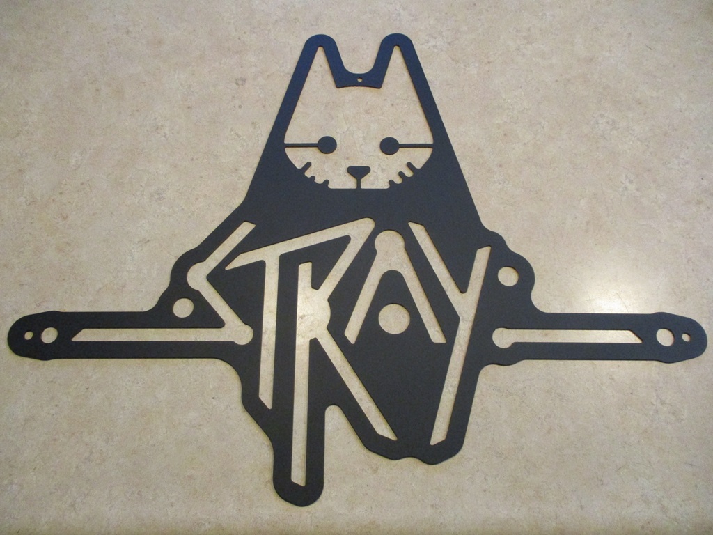
Last weekend I picked up 4 42x48 sheets of 1/8" steel to replenish my metal inventory. Then put the plasma cutter to work cutting out a bunch of parts for inventory.
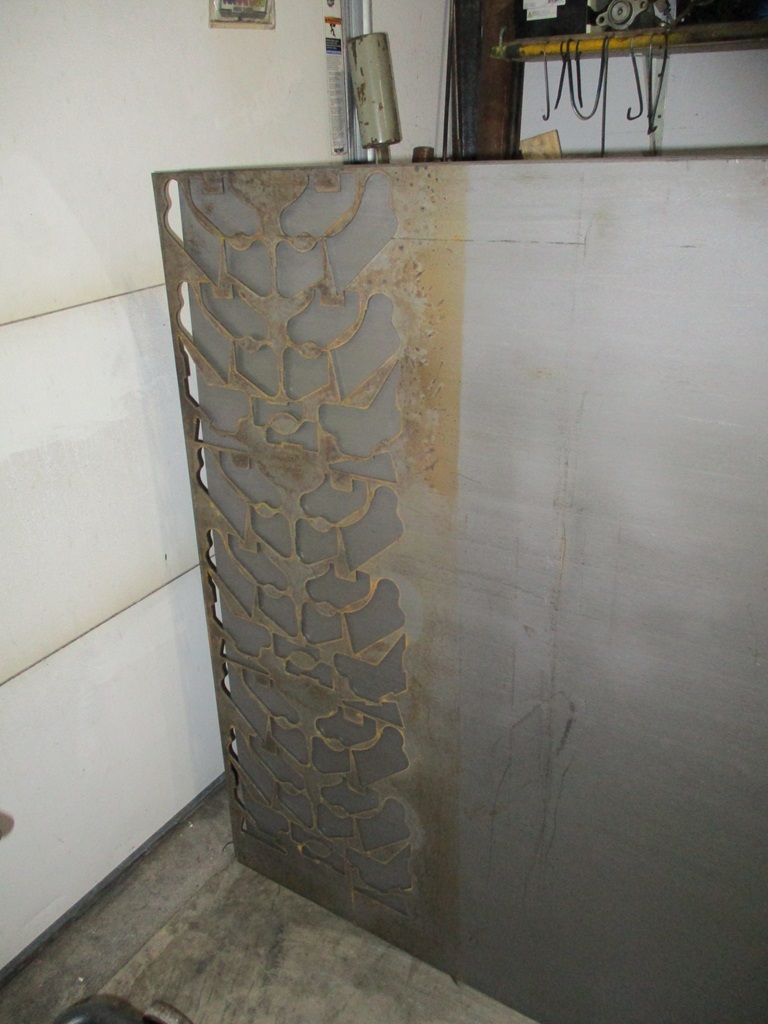
My youngest (sophomore in HS) had some interest in the CNC plasma, so I walked them through the cad layout, sheet cam tool selection and g-code generation, then using Mach 3 to run the plasma table. Here is the end result. I am told it is some kind of video game.
This weekend I was able to finish up installing the rod end lateral links and zero lash end links on the passenger side. From there it was time to align the car. 1/2" conduit with precise hole locations, 0.025" welding wire, some spare rotors to hold everything in place, then square the assembly to the wheel centers, then align. Only worried about rear toe and thrust angle this time.
Then I took the car out for a spin. My left ankle is about 80% and I am still wearing the brace, but didn't have any issues driving the car! Only put about 20 miles on it then put it back in the garage.
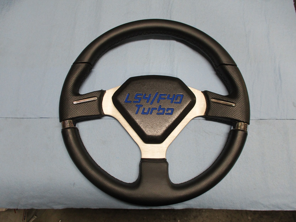
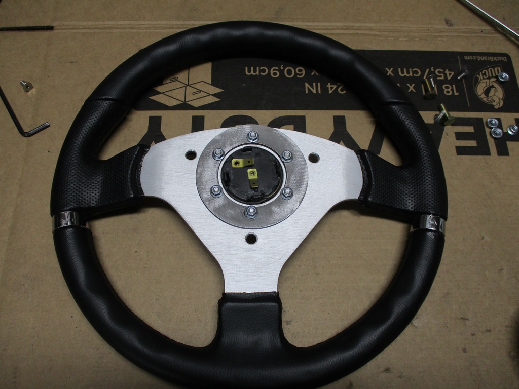
Back to working on the interior... I picked up a new steering wheel, but will have to modify it. I also wasn't feeling the center portion of the wheel and wanted something more custom. Here is the start too the new steering wheel center:
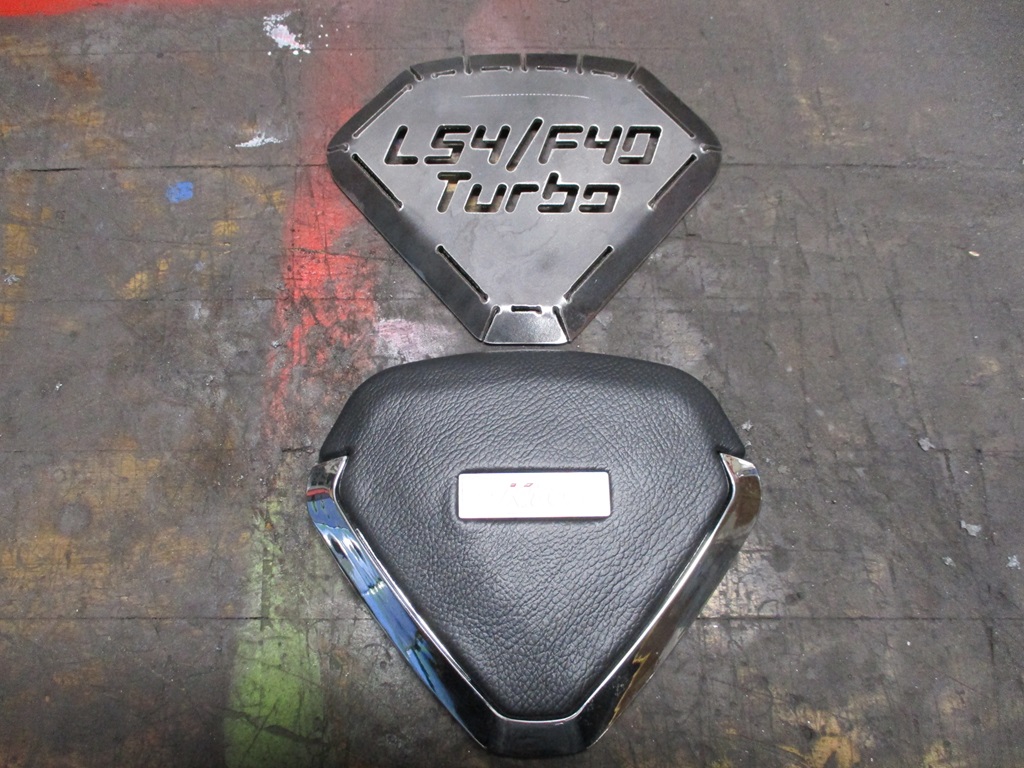
Still need to weld up all the slots, smooth everything back down and then work on the insert.
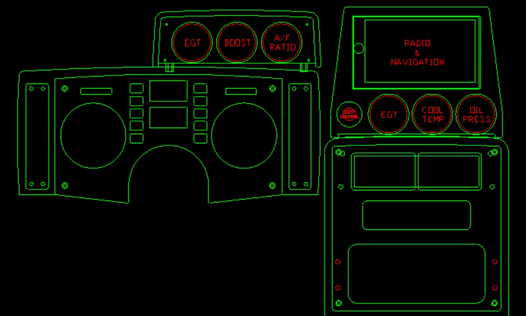
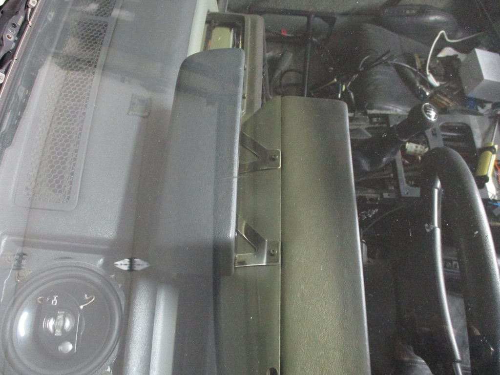
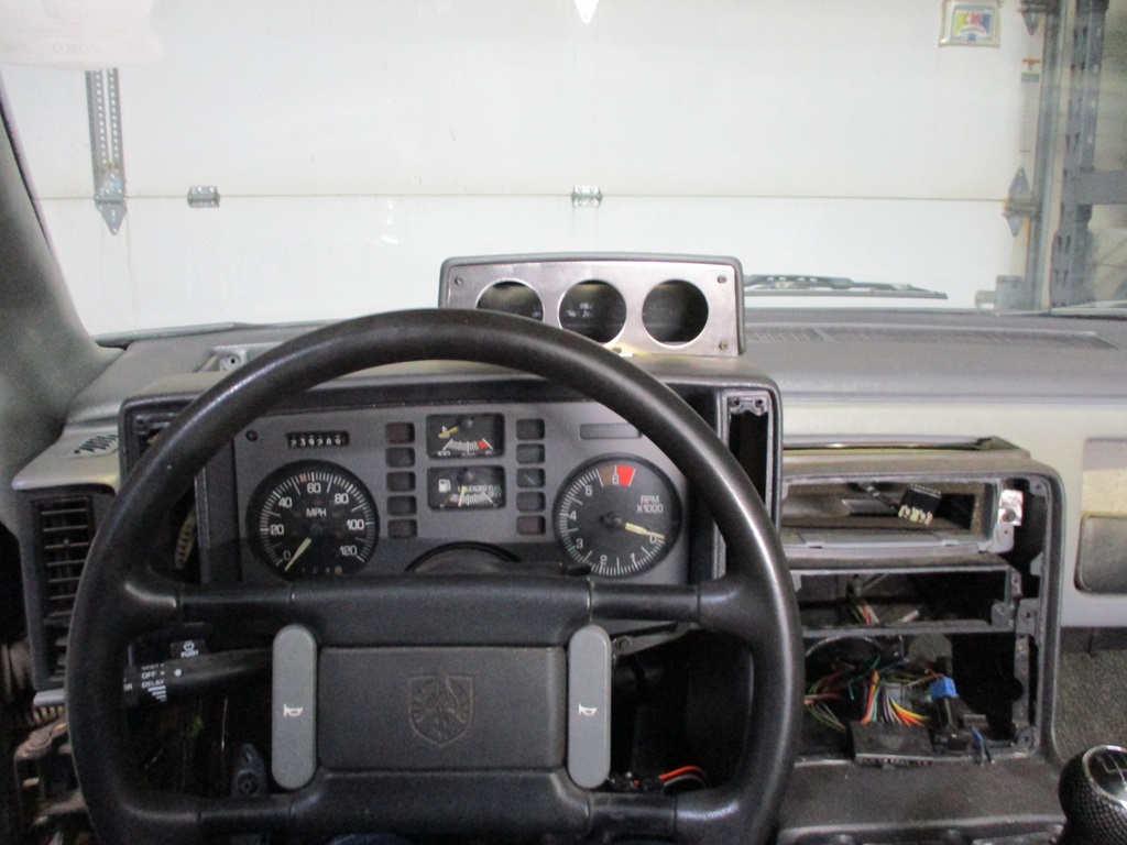
The current thought for all the gauges and 2din nav unit. Factory aux gauge housing with 3 gauges mounted over the instrument cluster and about 6-10" forward from the face of the instrument cluster. Then a custom housing where the aux gauges were to house 3 gauges, the manual boost control ****, and the 2DIN radio/nav unit.
The following 4 users liked this post by fieroguru:
02-11-2024, 03:27 PM
#507
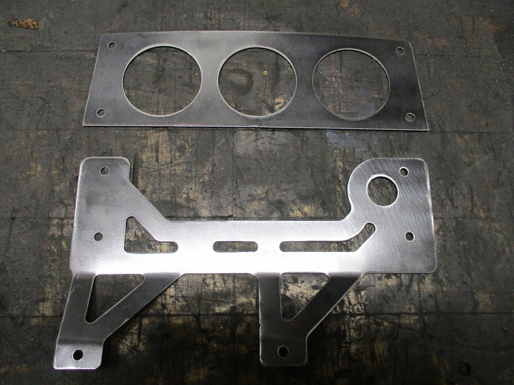
The work on the aux gauge bracket is almost done. It is designed to reuse two existing interior panel bolts, so it can be easily removed later if need be.
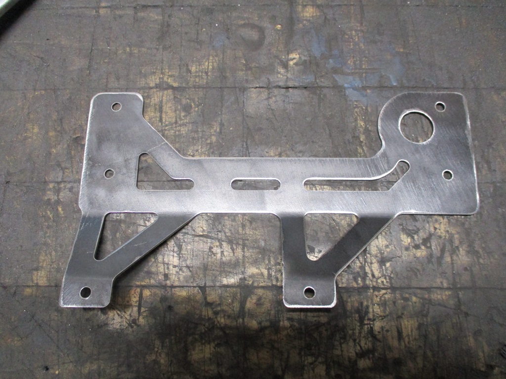
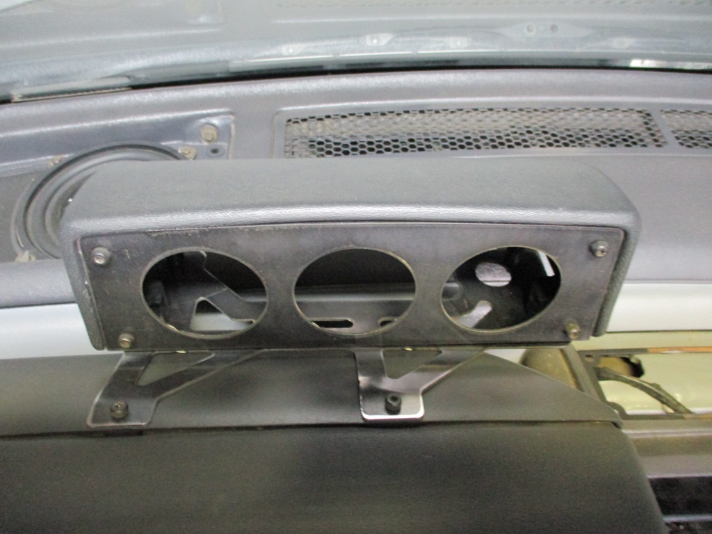
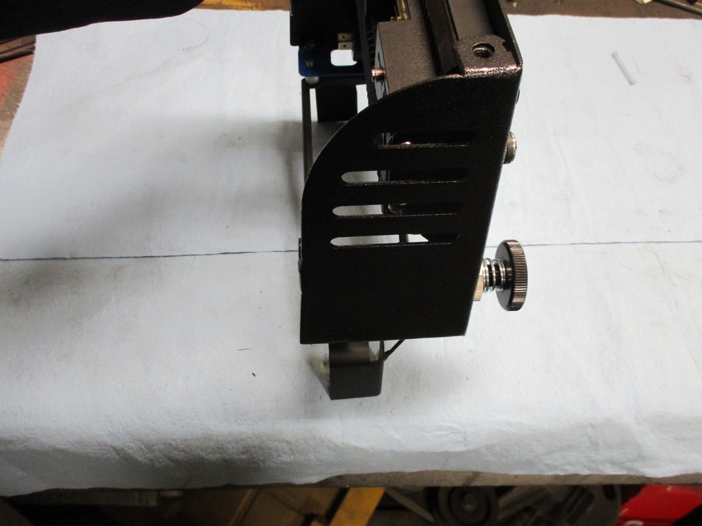
Then my focus shifted to the GPS/NAV unit. The original plan with it above the 2 1/16" gauges was too tall once it was mocked up... so it needed some reworking.
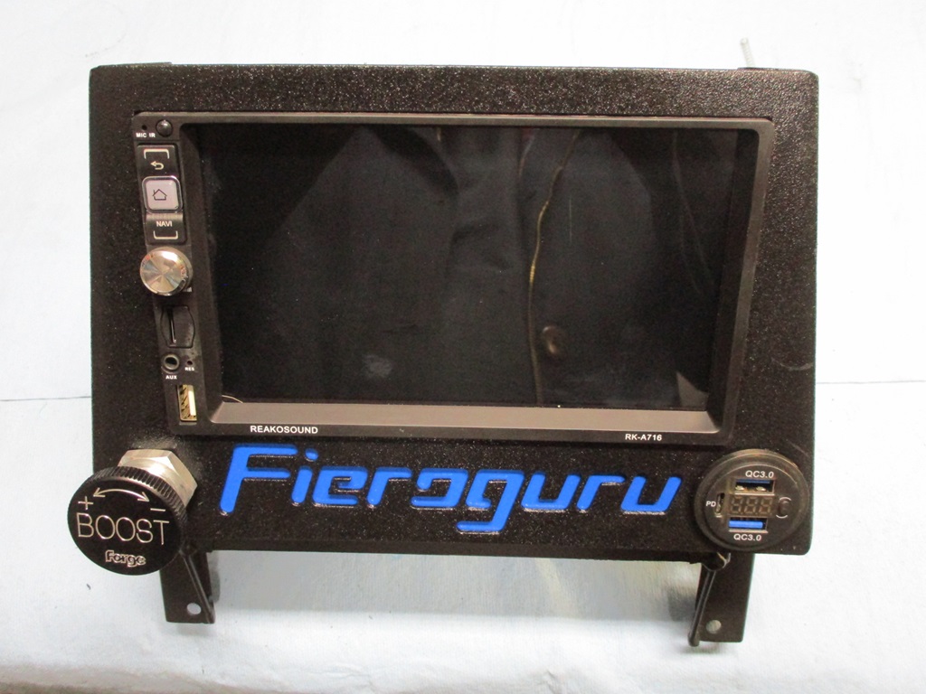
This is what I came up with.
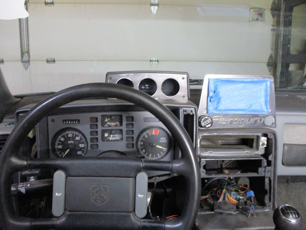
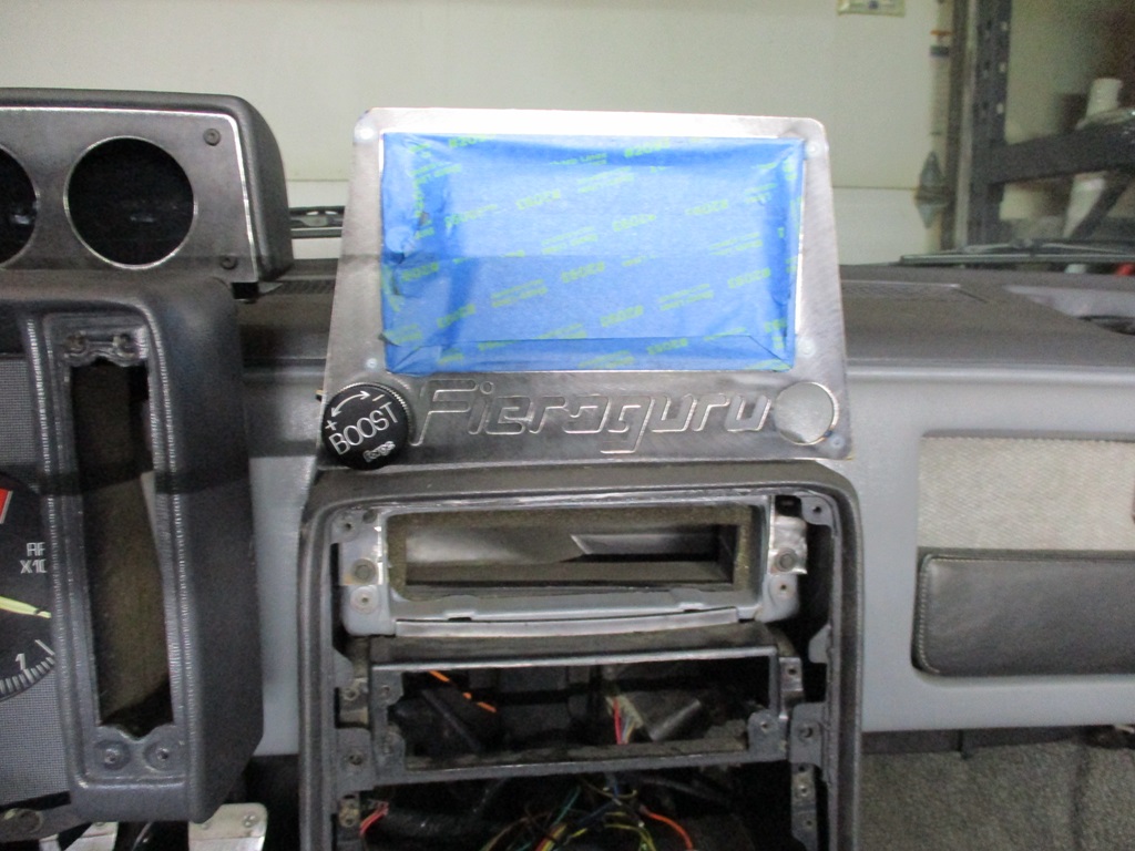
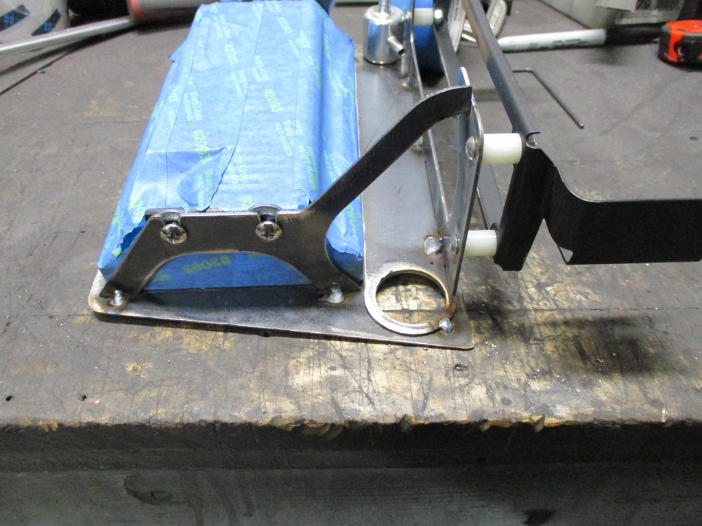
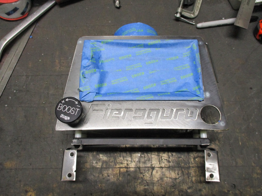
It kinda looks like an Etch A Sketch!
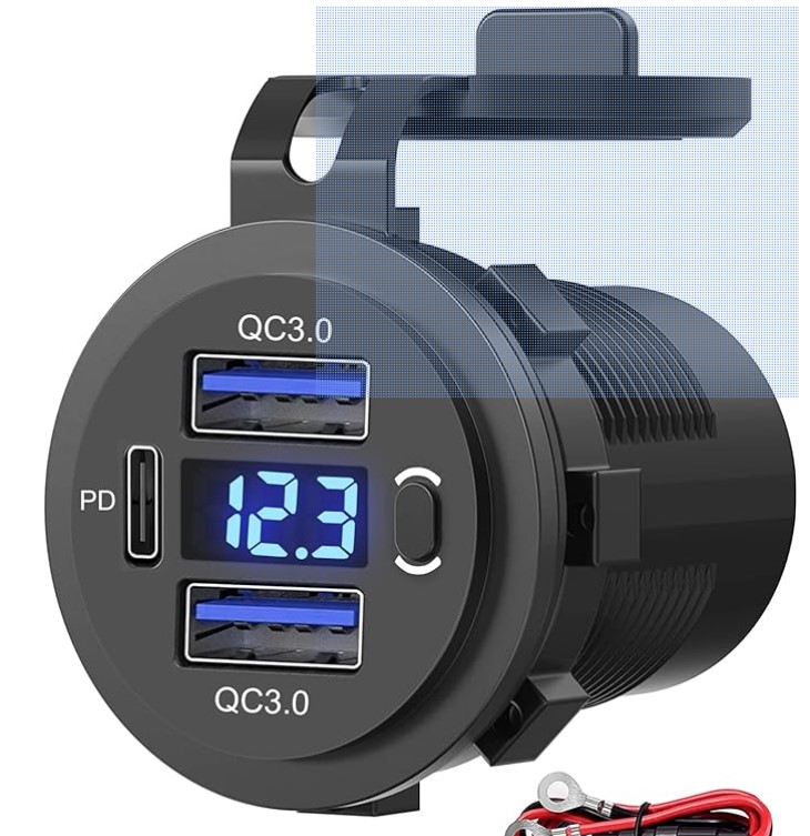
It reuses the stock aux gauge bracket so it is also a bolt in modification. The boost adjuster is on the lower left and on the lower right will be a 3 port USB charger with digital voltage display.
With this GPS/NAV mock up, I was able to update the drawings so the next version should be the final one.
Then my focus shifted to the GPS/NAV unit. The original plan with it above the 2 1/16" gauges was too tall once it was mocked up... so it needed some reworking.
This is what I came up with.
It kinda looks like an Etch A Sketch!
It reuses the stock aux gauge bracket so it is also a bolt in modification. The boost adjuster is on the lower left and on the lower right will be a 3 port USB charger with digital voltage display.
With this GPS/NAV mock up, I was able to update the drawings so the next version should be the final one.
The following users liked this post:
ryeguy2006a (02-12-2024)

The following users liked this post:
G Atsma (02-11-2024)
02-18-2024, 04:08 PM
#509
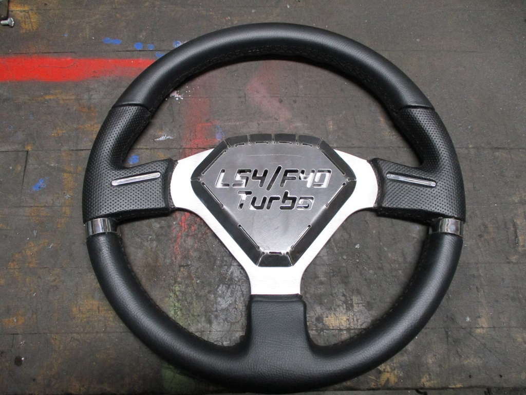
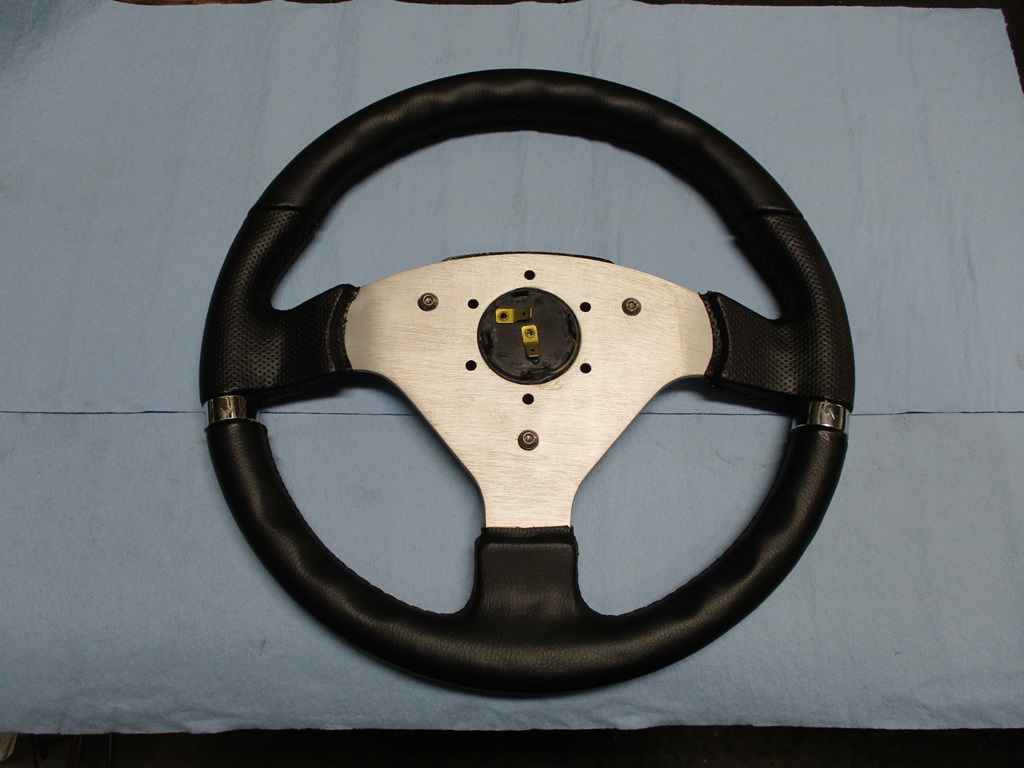
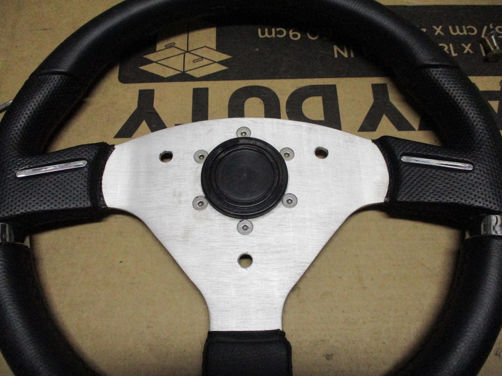
The steering wheel is getting closer. The center pod is finished. It is spring loaded and activates the horn puck that came with the wheel. Now I need to fabricate the adapter to allow it to mount to the Fiero column.
The new center piece reuses the same 3 bolts as the original center.
The radio/NAV face, sides and base are complete. Still need to finish the top/back panel. Thinking it will be aluminum.
I ended up removing the lower slots on the side and just kept the top 4 (2 are to access the bolts holding the radio in place).
Here is the business side:
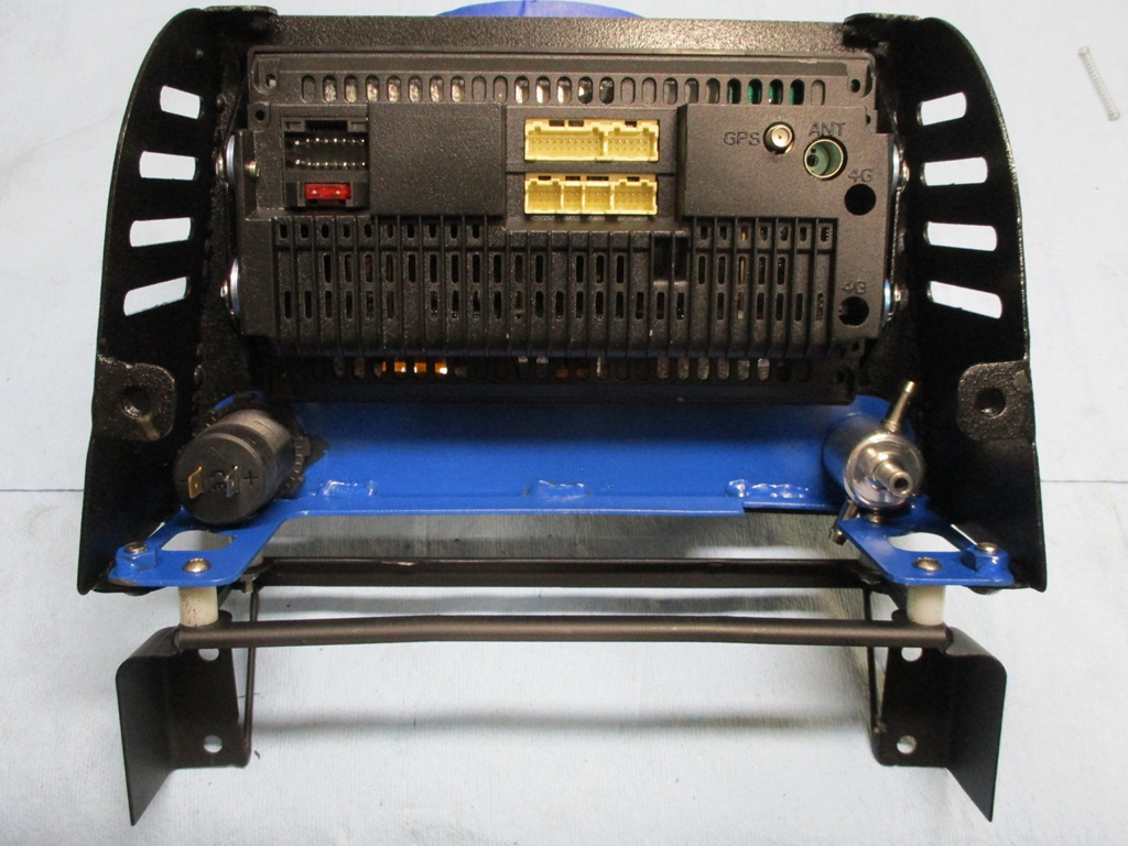
Also started looming up the 3 gauges - A/F ratio, Boost, and Fuel Pressure:
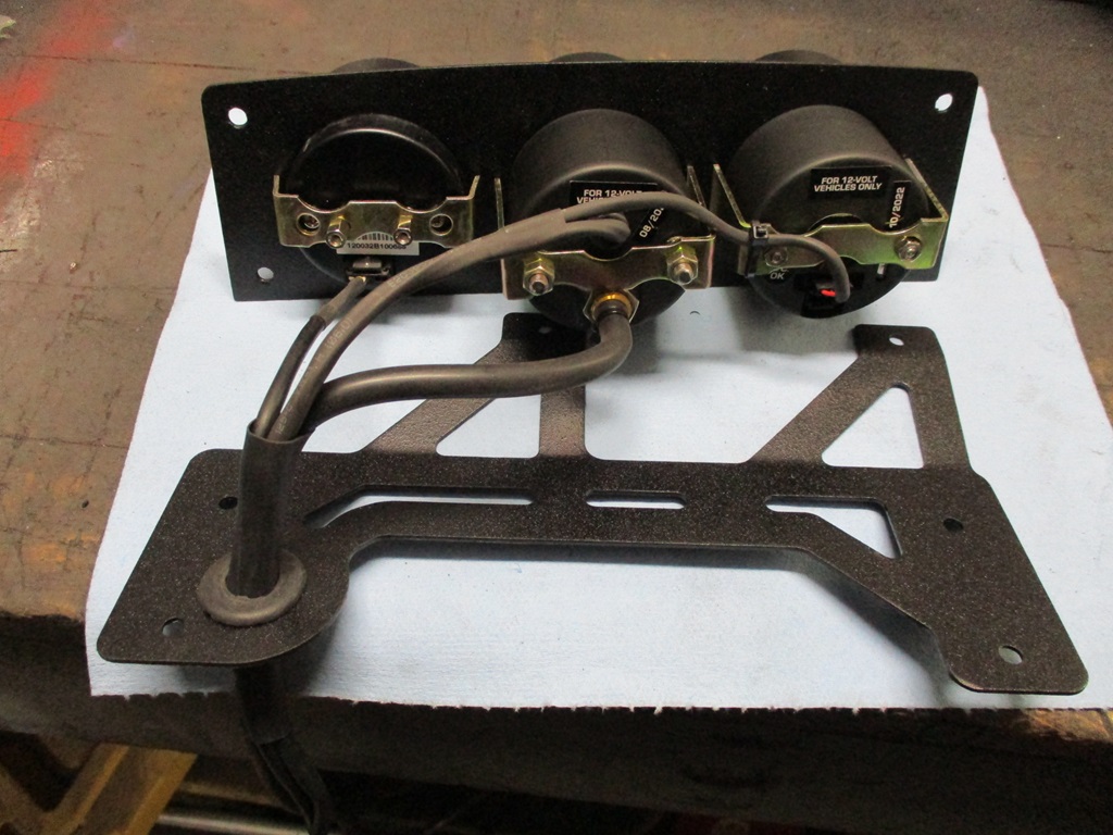
Gauge pod ready to be installed:
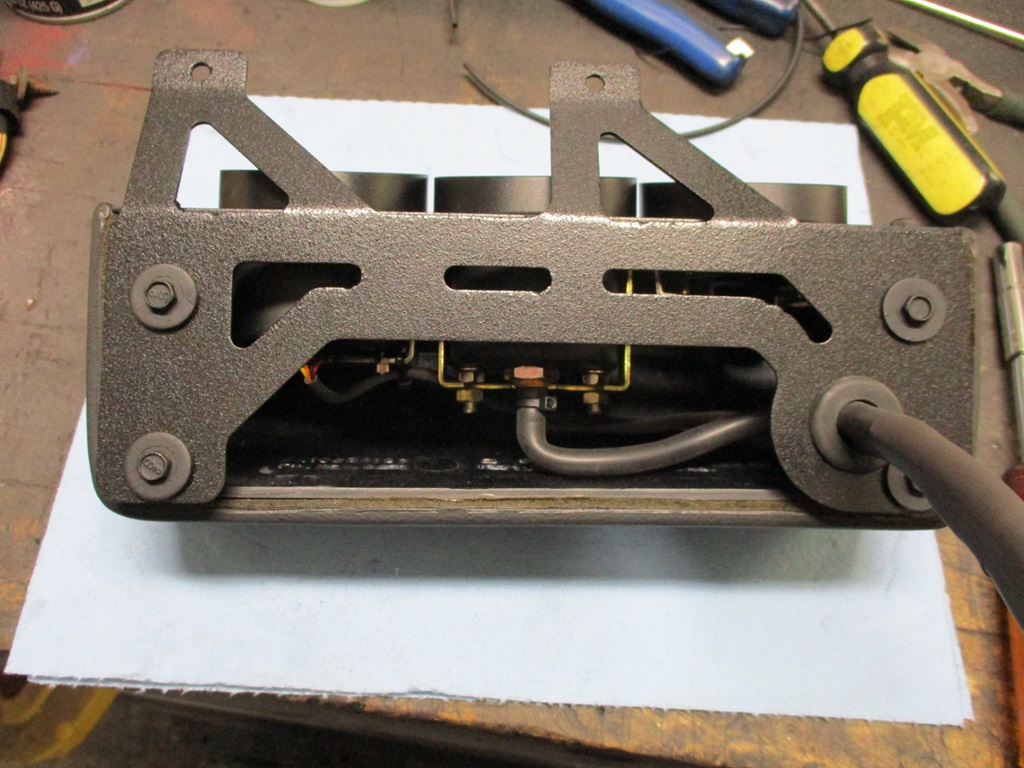
Gauges and Radio/NAV unit installed:
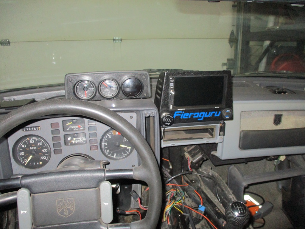
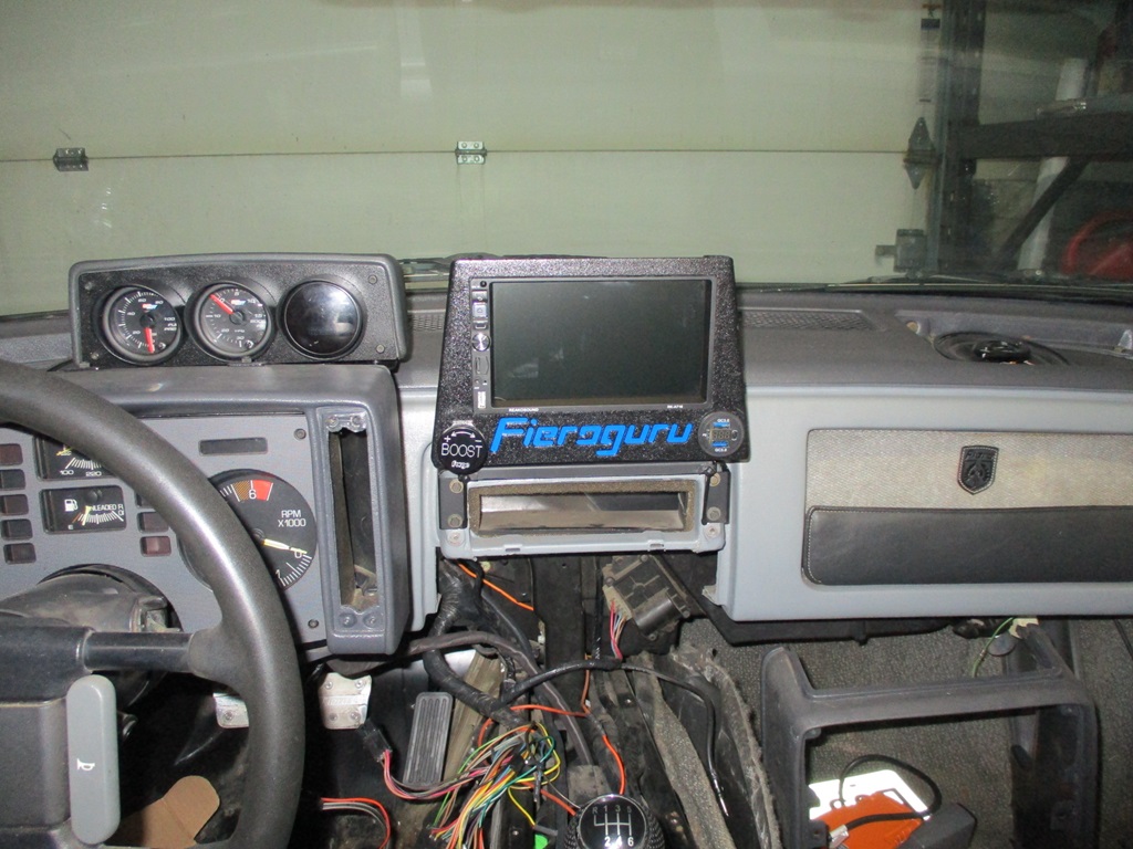
Now I can pull the dash and install the front speakers, the amp and wire up the radio...
The new center piece reuses the same 3 bolts as the original center.
The radio/NAV face, sides and base are complete. Still need to finish the top/back panel. Thinking it will be aluminum.
I ended up removing the lower slots on the side and just kept the top 4 (2 are to access the bolts holding the radio in place).
Here is the business side:
Also started looming up the 3 gauges - A/F ratio, Boost, and Fuel Pressure:
Gauge pod ready to be installed:
Gauges and Radio/NAV unit installed:
Now I can pull the dash and install the front speakers, the amp and wire up the radio...
The following users liked this post:
ryeguy2006a (02-19-2024)
02-26-2024, 09:04 PM
#510
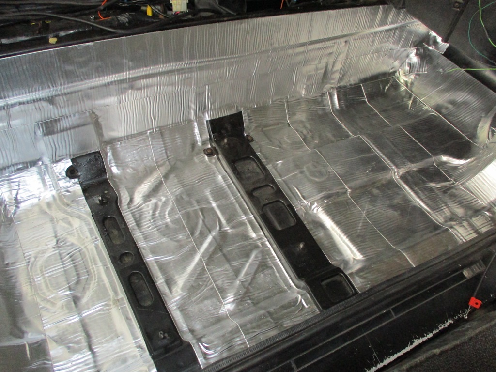
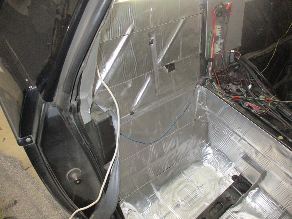
Currently have all the interior back out adding sound deadening. Passenger side is done:
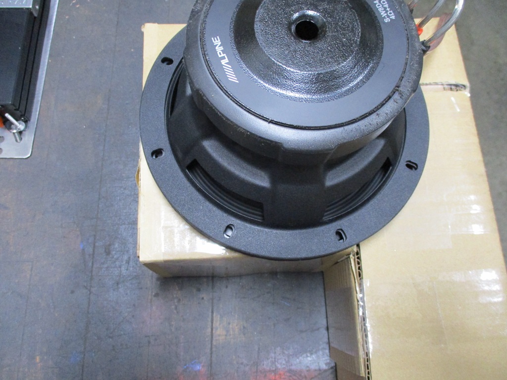
Also wired up the stereo amp and all the alpine speakers up on the bench to test them out.
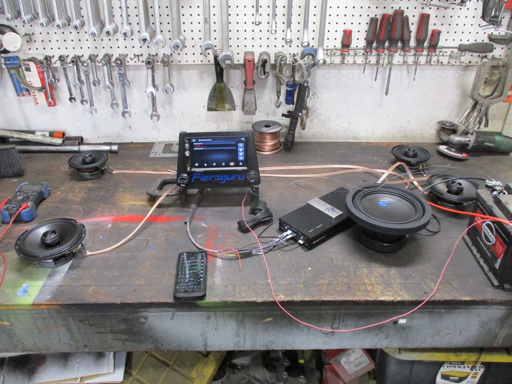
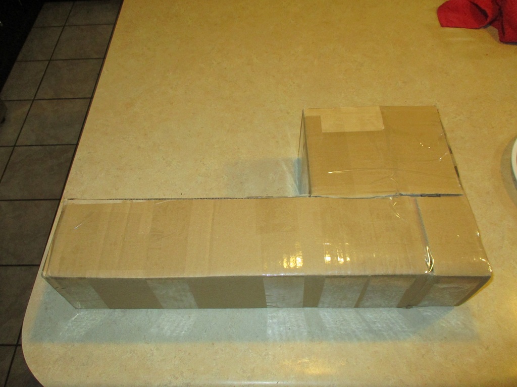
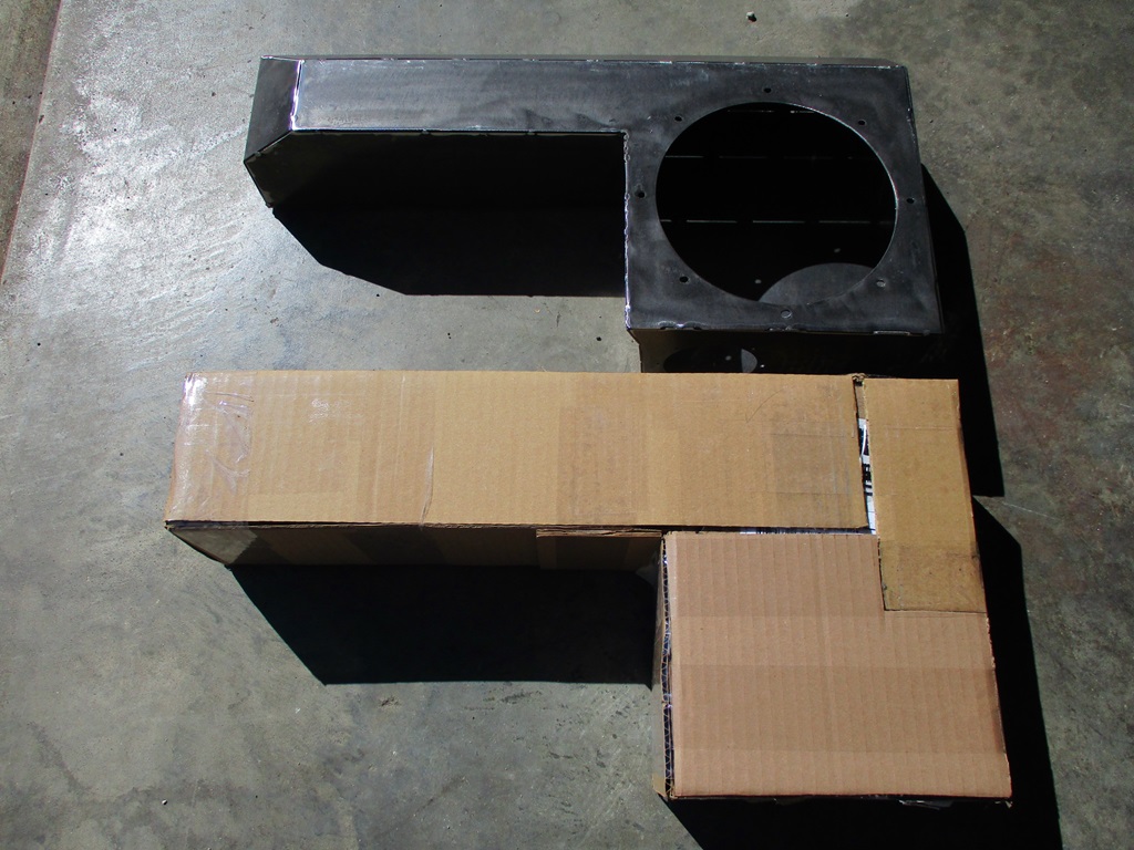
Played with some cardboard to mockup the box. This box is very similar to Alex4mula's, except it is 4.5" tall, the front tube is 4.5" deep, and the overall length/width is 20.75 x 10.5". I plan to make this out of 16ga steel vs. 1/2" MDF. Partly because the CNC plasma makes cutting these types of things easy and partially because it allows more air space in a smaller package.
With the relatively small span I don't expect the box will flex much.
As for the weight, a 4x8 sheet of 1/2" MDF is 66 lbs and a 4x8 sheet of 16ga steel is 81.7 lbs. so it would be easy to say the use of 16ga vs. 1/2" MDF will have the box weigh about 24% more. However, with the dimensions of Alex4mulas box remaining the same, the 1/2" MDF has 0.248 ft^3 and using 16ga is 0.376 ft ^3 or about 53% more interior volume. So, when you build a box to a specific volume, the steel one can be smaller, use less material, and overall be lighter.
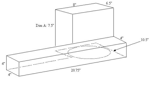
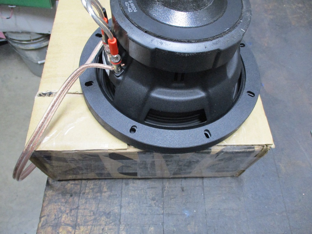
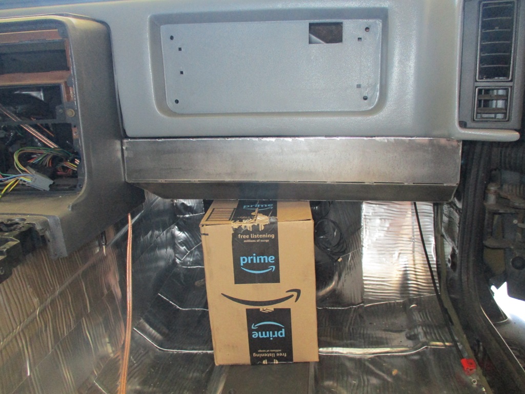
The 4.5" thickness easily clears the speaker magnet and subwoofer depth:
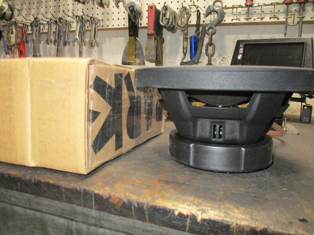
The 8" width portion has the sub flange hanging off the sides slightly, and from the mockup this could be wider as there is room on both sides - especially at the elevation of the sub flange.
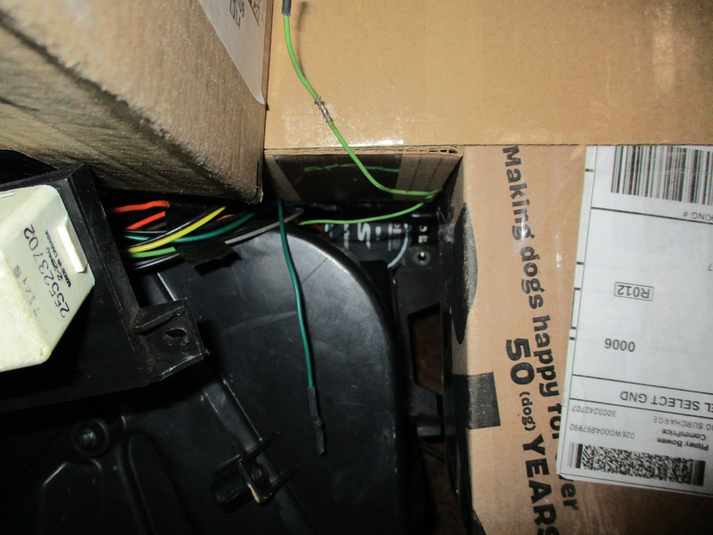
This is looking up from the floor to the box and the side where the sub would be mounted and there is a gap on both sides.
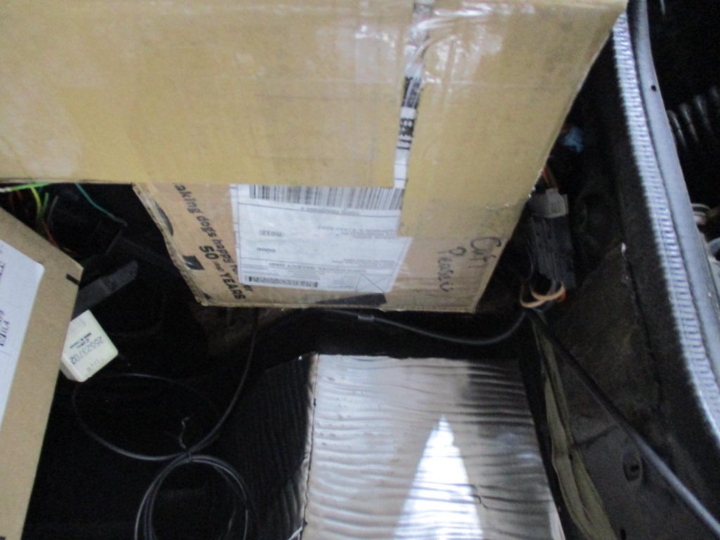
Here is the current clearance to the heater core. By removing the bracket, the box could be a little wider in the back:
Here is a pic of the box installed from the front:
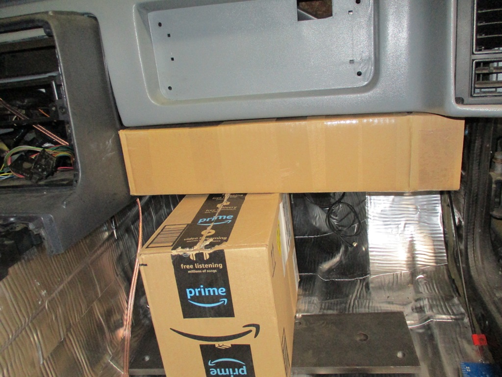
The recommended sealed volume for my sub is 0.30 ft^3 and this mock up box is 0.345 ft^3 so I need to make it a little smaller.
Current plan is to reduce the overall height by 1/4", reduce the front tube depth by 1/4", adding a 1 1/2" x 1 1/2" 45 degree taper at the lower corner of the front tube, and probably something along the outside edge as well.
The flat pattern is too large to cut as a single piece on the cnc plasma, but I can easily cut it in 2 pieces.
Also wired up the stereo amp and all the alpine speakers up on the bench to test them out.
Played with some cardboard to mockup the box. This box is very similar to Alex4mula's, except it is 4.5" tall, the front tube is 4.5" deep, and the overall length/width is 20.75 x 10.5". I plan to make this out of 16ga steel vs. 1/2" MDF. Partly because the CNC plasma makes cutting these types of things easy and partially because it allows more air space in a smaller package.
With the relatively small span I don't expect the box will flex much.
As for the weight, a 4x8 sheet of 1/2" MDF is 66 lbs and a 4x8 sheet of 16ga steel is 81.7 lbs. so it would be easy to say the use of 16ga vs. 1/2" MDF will have the box weigh about 24% more. However, with the dimensions of Alex4mulas box remaining the same, the 1/2" MDF has 0.248 ft^3 and using 16ga is 0.376 ft ^3 or about 53% more interior volume. So, when you build a box to a specific volume, the steel one can be smaller, use less material, and overall be lighter.
The 4.5" thickness easily clears the speaker magnet and subwoofer depth:
The 8" width portion has the sub flange hanging off the sides slightly, and from the mockup this could be wider as there is room on both sides - especially at the elevation of the sub flange.
This is looking up from the floor to the box and the side where the sub would be mounted and there is a gap on both sides.
Here is the current clearance to the heater core. By removing the bracket, the box could be a little wider in the back:
Here is a pic of the box installed from the front:
The recommended sealed volume for my sub is 0.30 ft^3 and this mock up box is 0.345 ft^3 so I need to make it a little smaller.
Current plan is to reduce the overall height by 1/4", reduce the front tube depth by 1/4", adding a 1 1/2" x 1 1/2" 45 degree taper at the lower corner of the front tube, and probably something along the outside edge as well.
The flat pattern is too large to cut as a single piece on the cnc plasma, but I can easily cut it in 2 pieces.
The following users liked this post:
ryeguy2006a (02-27-2024)
02-28-2024, 06:07 AM
#512
Thanks!
Many members of the Fiero community are very creative and come up with unique ideas or creations (like Alex4mula and this sub box concept). When I refine someone else's concept, I like to give them credit for the original idea.
Fieros have been my singular automotive focus since around 2003 and with my background in mechanics, machining/fabrication, mechanical engineering and continuous improvement methods and every growing list of tools and equipment, I am always thinking about and refining ideas for my personal Fiero
03-02-2024, 06:35 PM
#513
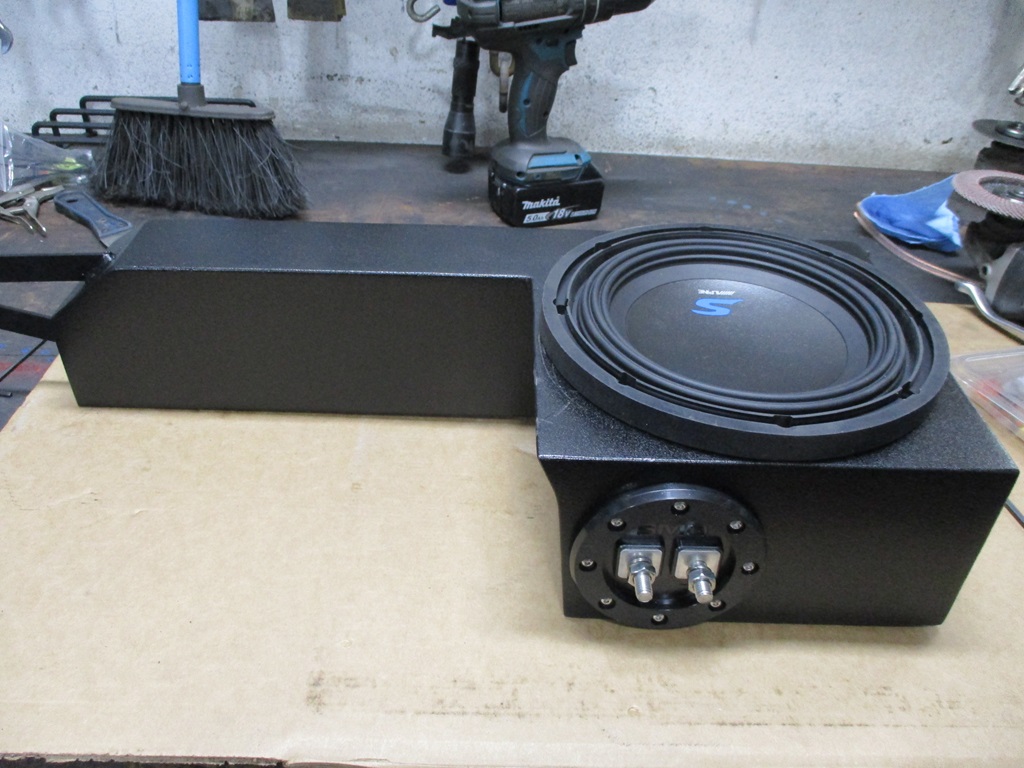
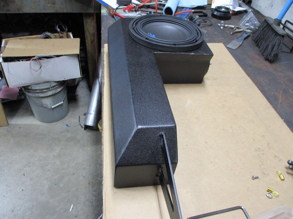
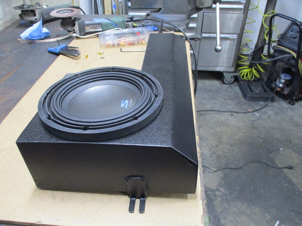
Got the sub box cut out and bent into shape.
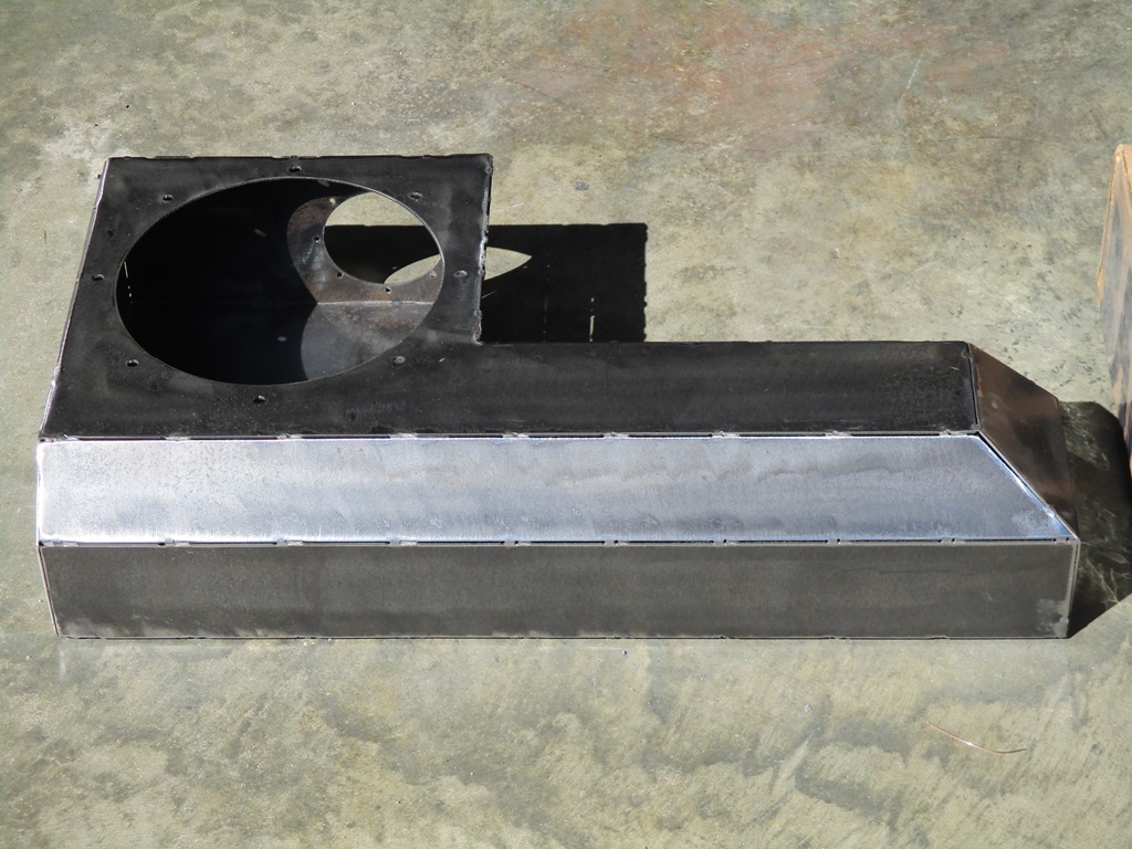
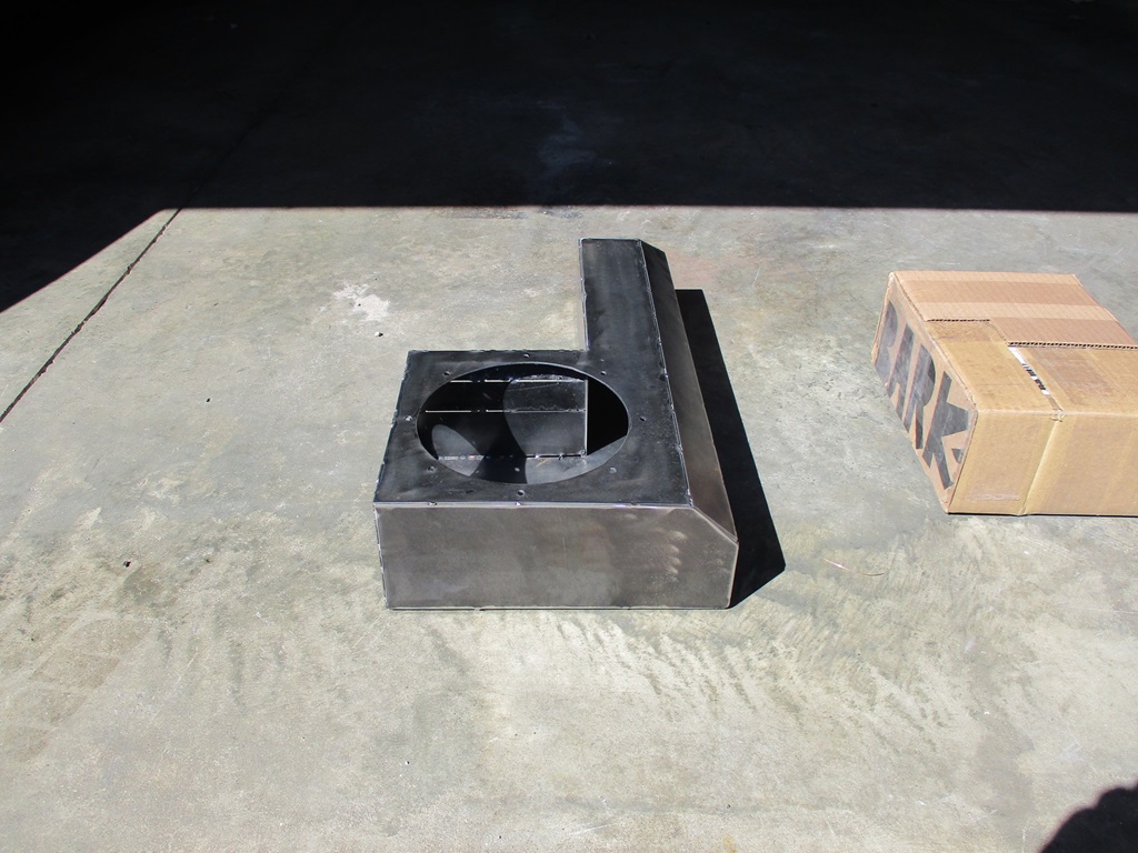
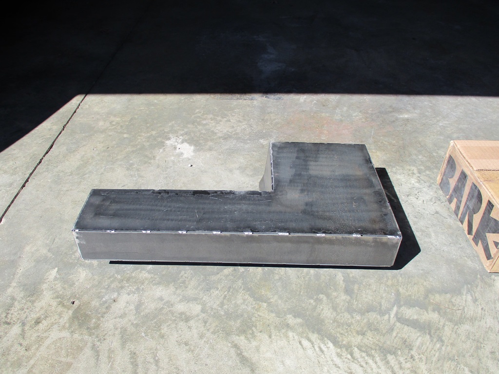
Another test fit.
Then I taped up all the seams and the connector hole, installed the sub and did some testing. Sounded better than just the sub sitting on bench. No noticeable resonance or other tone changes when I touch different sections of the car.
Not shown in the pictures was the 2nd ring with nuts welded to it that welded on the inside of the box. This way I can bolt the sub in place with M6 bolts and not with just sheet metal screws.
I now have about 95% of the sub box welded up (ran out of welding gas) and have started smoothing the welds. I think I have some flux core wire I can use to finish off the welding... or I could tig it.
On Sunday I would like to get the welds smoothed and the mounting brackets attached. I might even get to the point of painting and texturing it.
03-03-2024, 05:38 PM
#514
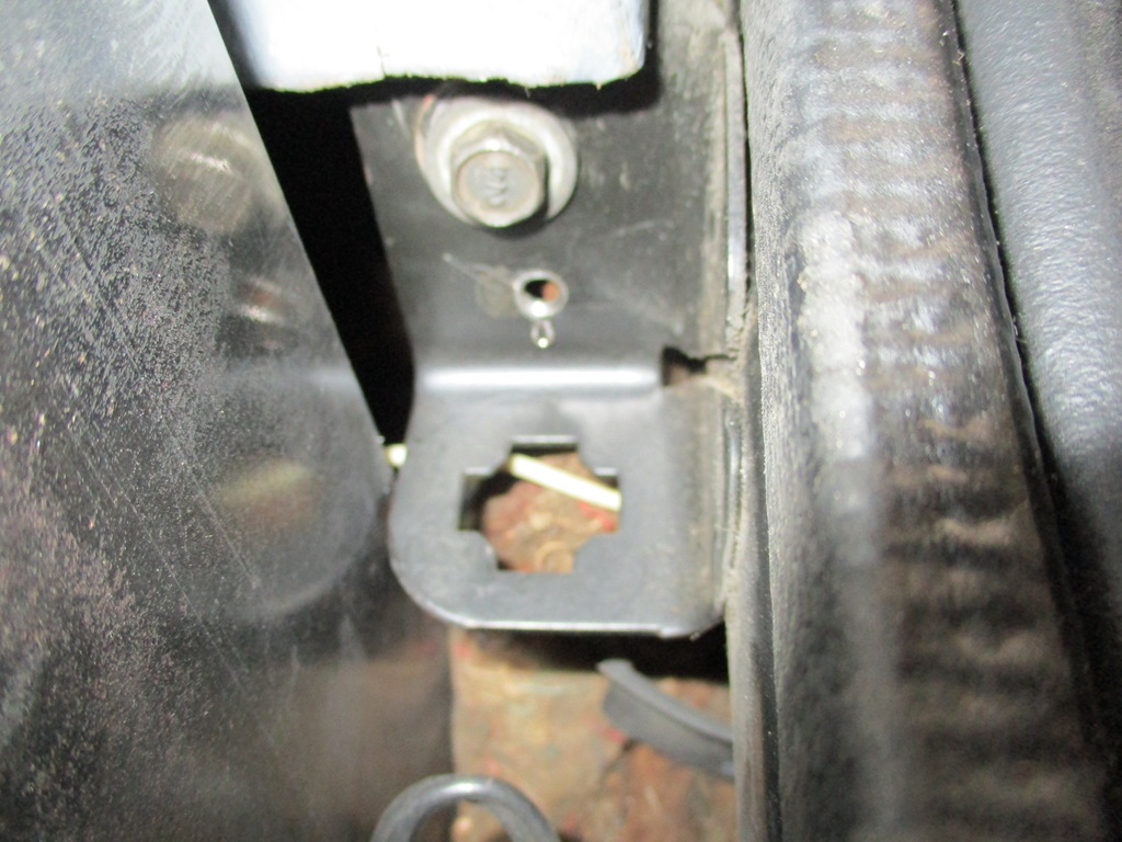
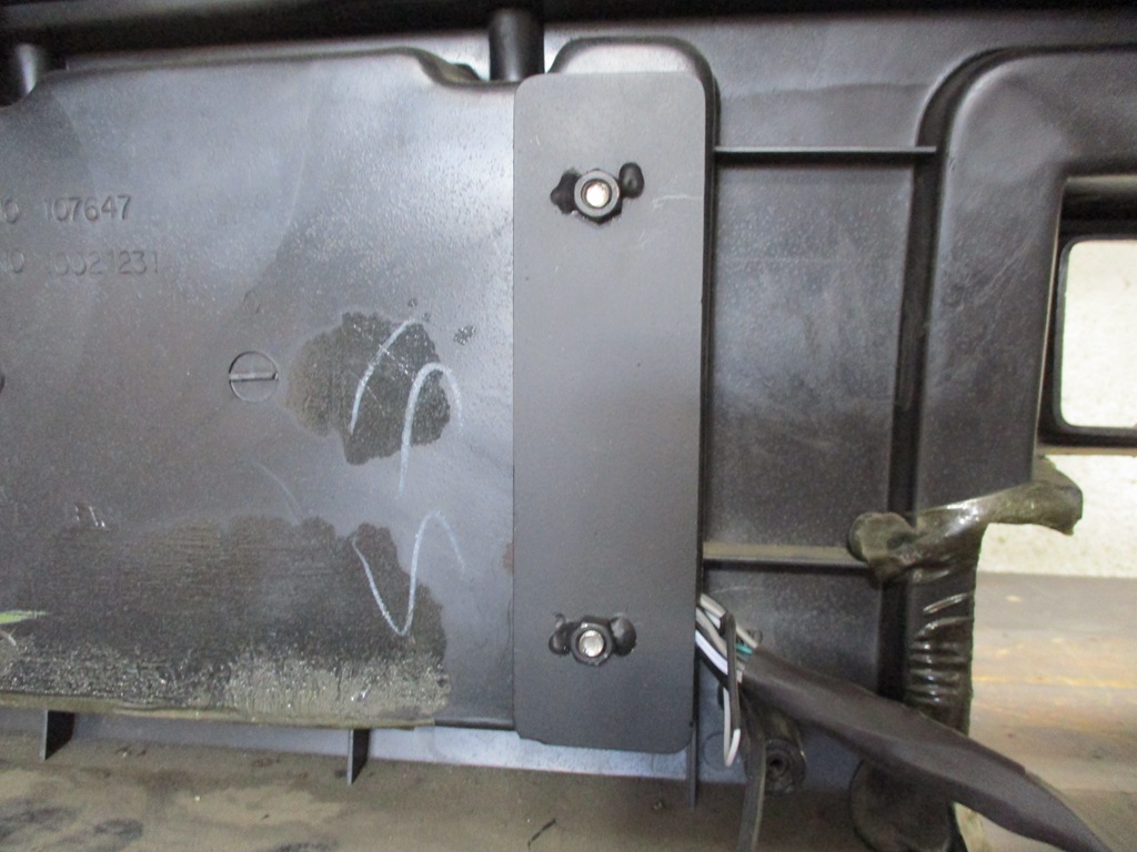
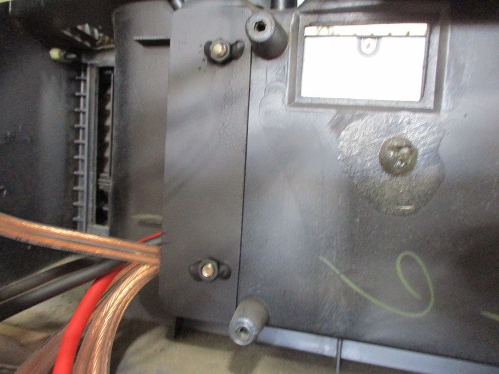
Smoothed all the welds on the sub box, then put it back in the car to start working on mounts for it. For the left side, I made a bracket that will bolt to the steering column support tube in the center console. It is far enough back to clear the console skeleton and surround.
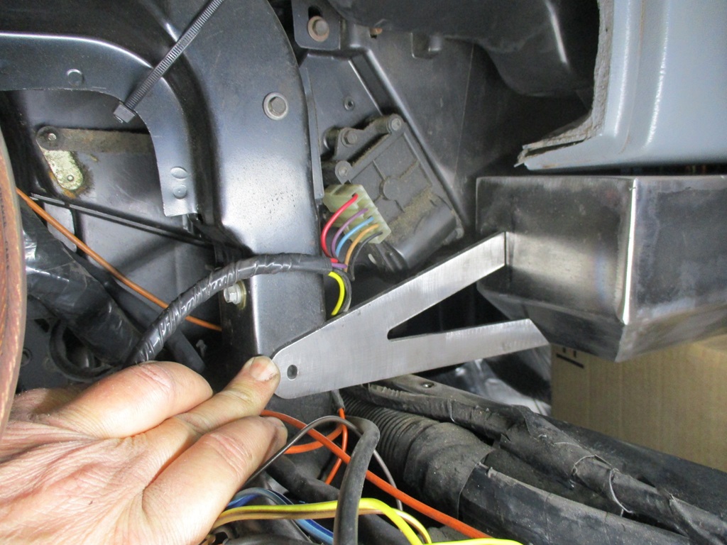
The bracket for the right side will just be a L bracket with a hole in it to pick up this bolt:
Put the welding gas bottle in the back of the truck so I can get it filled on Monday.
Then i went back to the steering wheel and the brackets needed for attachment.
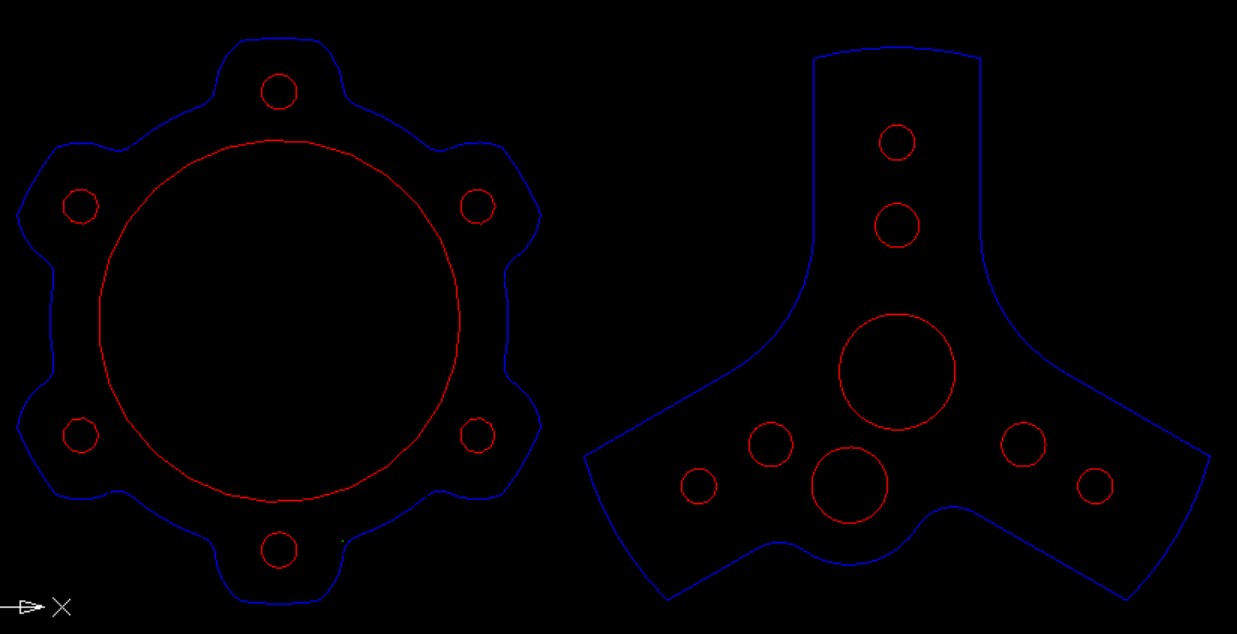
Here is a general mock up drawing showing the aluminum splined flange, two blue adapter plates and the red part is an exhaust reducer. The plates and the exhaust reducer will be welded together to make the steering wheel adapter mount.
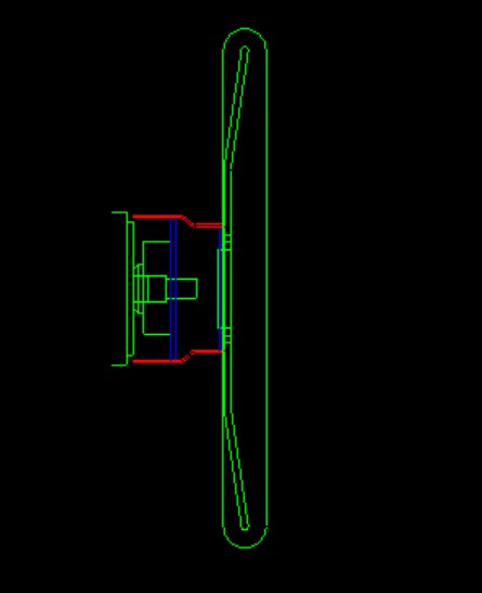
Here are some of the older plates before the design was further refined:
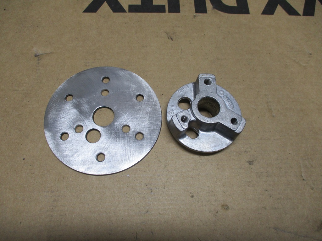
This is what the final design of the two adapter plates will look like:
The bracket for the right side will just be a L bracket with a hole in it to pick up this bolt:
Put the welding gas bottle in the back of the truck so I can get it filled on Monday.
Then i went back to the steering wheel and the brackets needed for attachment.
Here is a general mock up drawing showing the aluminum splined flange, two blue adapter plates and the red part is an exhaust reducer. The plates and the exhaust reducer will be welded together to make the steering wheel adapter mount.
Here are some of the older plates before the design was further refined:
This is what the final design of the two adapter plates will look like:
03-10-2024, 03:43 PM
#515
Another productive weekend doing small fiddly stuff, but it needed done.
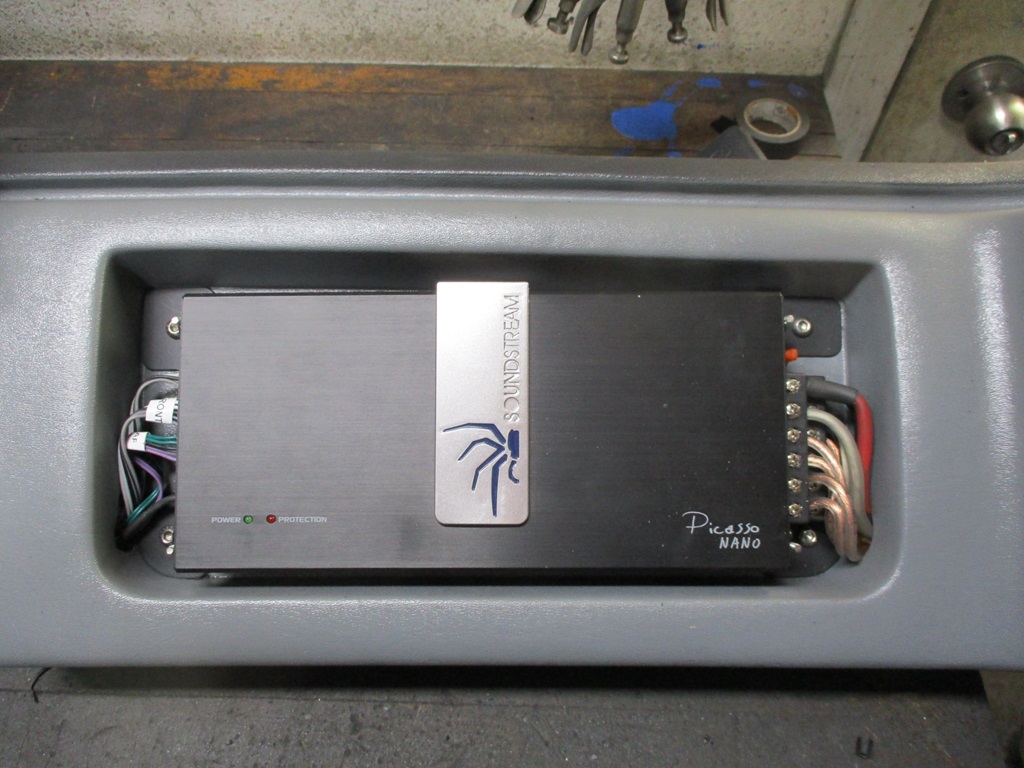
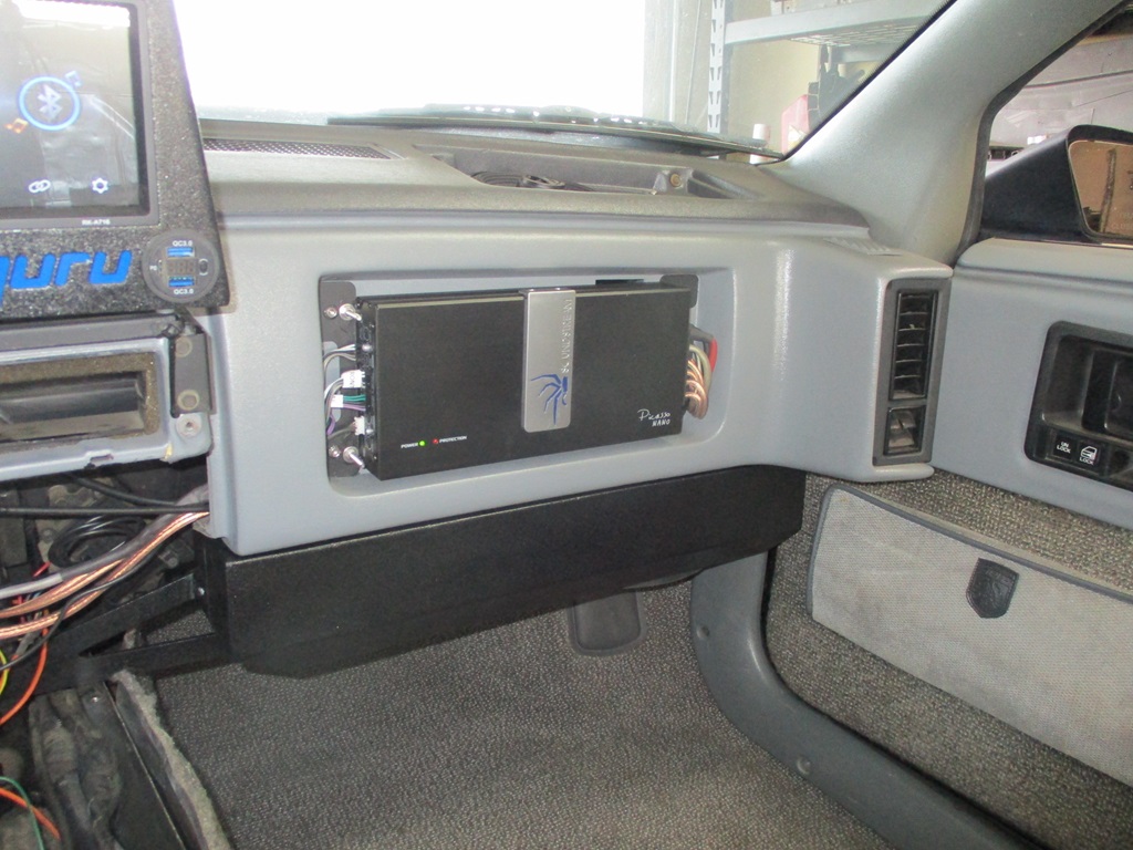
Mounted and wired the amp. The initial plan was to have to wires go through the wall of the pocket, but they would not clear the HVAC tube, so I made a wiring access hole in the bottom of each corner. The amp weighs 5 lbs, so I added support plates for the 4 bolt holes that secure it.
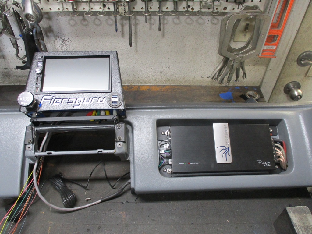
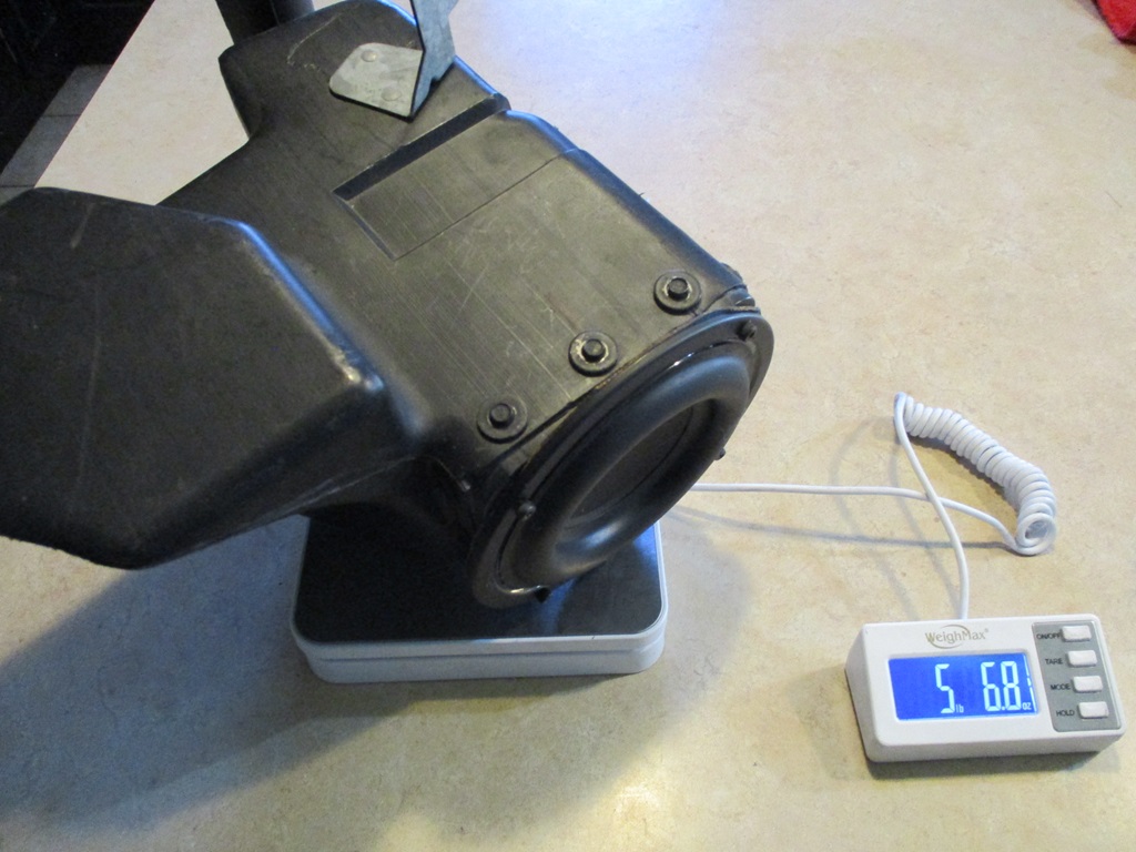
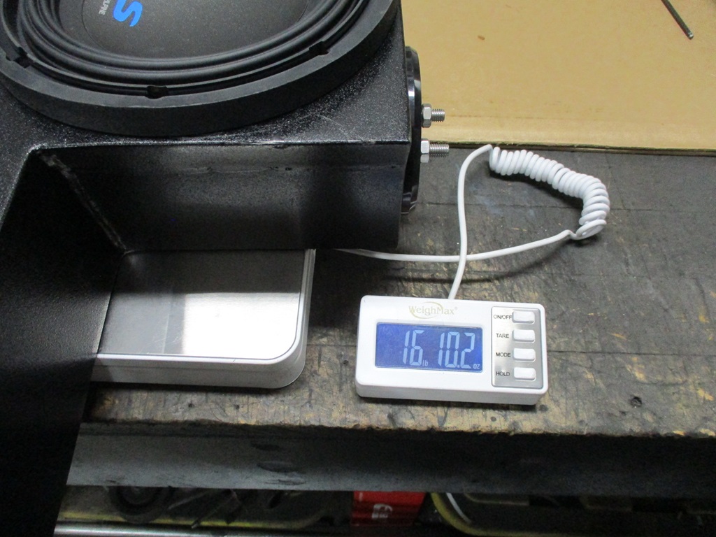
The sub box is also done. It weights 16 lbs 10oz and the stock sub housing with the the larger woofer is 5lbs 7 oz, so 11 lbs more for the sub and 5 for the amp, so all the stereo mods will be in the 20 to 25 lb range, which i am OK with.
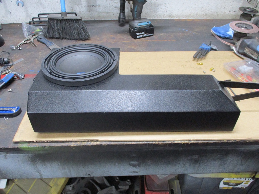
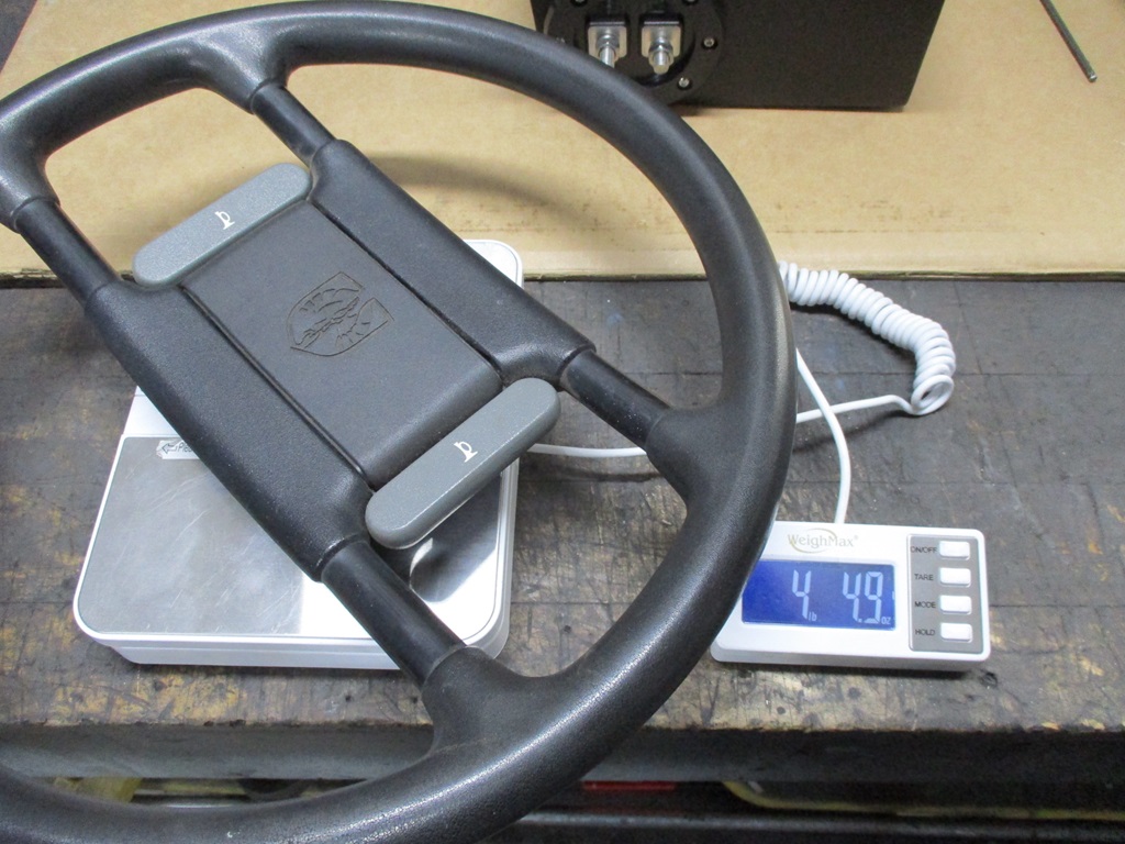
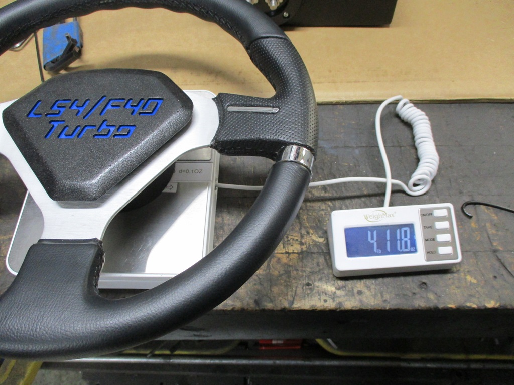
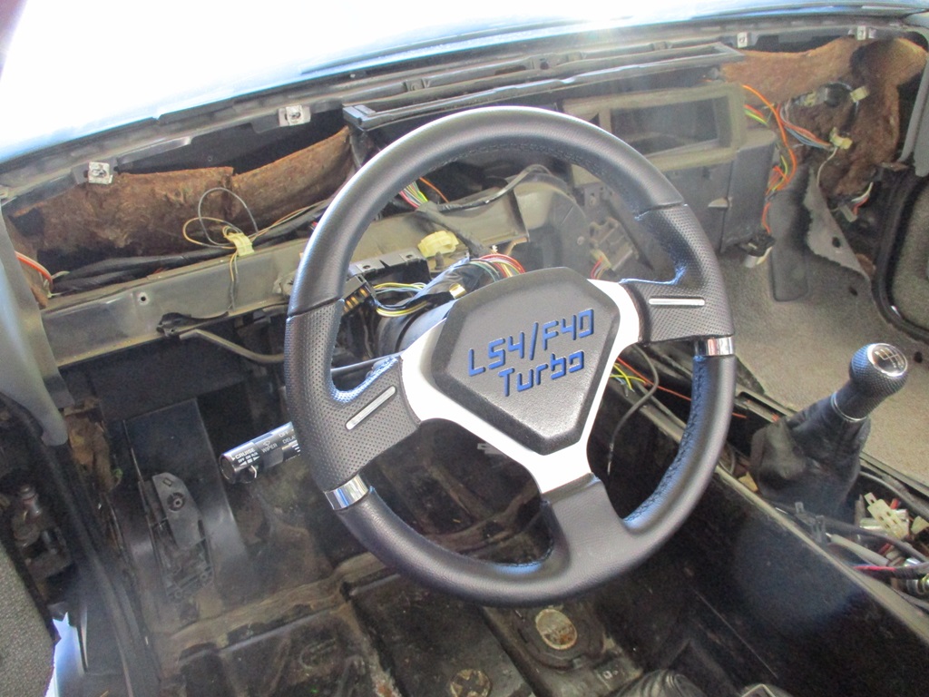
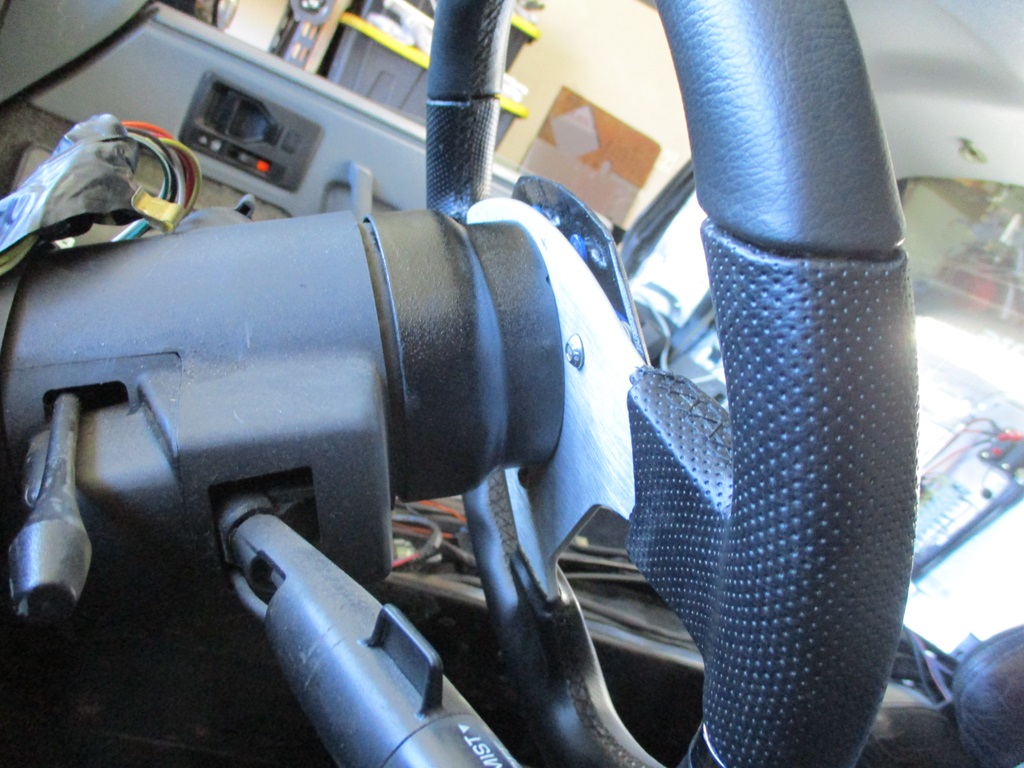
The steering wheel adapter is now done as well. It isn't fully tight yet, so the gap between the adapter and the column will be a little less. All the steering wheel custom-ness weighs 1/2 lb more than the stock steering wheel.
Mounted and wired the amp. The initial plan was to have to wires go through the wall of the pocket, but they would not clear the HVAC tube, so I made a wiring access hole in the bottom of each corner. The amp weighs 5 lbs, so I added support plates for the 4 bolt holes that secure it.
The sub box is also done. It weights 16 lbs 10oz and the stock sub housing with the the larger woofer is 5lbs 7 oz, so 11 lbs more for the sub and 5 for the amp, so all the stereo mods will be in the 20 to 25 lb range, which i am OK with.
The steering wheel adapter is now done as well. It isn't fully tight yet, so the gap between the adapter and the column will be a little less. All the steering wheel custom-ness weighs 1/2 lb more than the stock steering wheel.
The following 2 users liked this post by fieroguru:
Project GatTagO (03-10-2024), ryeguy2006a (03-19-2024)
03-10-2024, 09:55 PM
#516
Launching!

You made your sub box out of steel? What did you do to treat the box against ringing/resonance?
03-11-2024, 06:04 AM
#517
Most of the sections are only 4 1/4" wide, so the 16ga is quite stiff with that short of span and doesn't ring. The panel directly opposite the sub is the largest and the one of concern. After the welding, I could push that panel in/out with minimal effort. To stiffen it, I beat about a 1/4" concave crown(from the back of the sub's perspective) into it to preload the panel and keep it from flexing in/out. I had the box resting on a large open hat side of a 13" rotor, then I took a 2x4 and a mini sledge and went around the diameter of the sub opening giving the panel on the bottom (actually the top panel on the sub box) some heavy hits to bend it outboard some.. I tested the sub box on the bench and it didn't have any ringing or flexing. As the last step, inside the box all panels are lined with the same sound deadening material as the floor boards of the car.
The following 2 users liked this post by fieroguru:
G Atsma (03-11-2024), JoshHefnerX (03-11-2024)
03-11-2024, 09:12 AM
#518
Launching!
Someday if we ever cross paths, I'd like to give that a listen. Have built many enclosures over the years and noodled over steel but never dared.
The following users liked this post:
fieroguru (03-13-2024)
The following 2 users liked this post by fieroguru:
BFromTheD (04-02-2024), JoshHefnerX (03-11-2024)
03-17-2024, 08:02 PM
#520
Only got to work on the car today... pulled front passenger wheel and wheel liner to run the fused 8ga amp wire to the battery. The amp battery cable passed from the inside to outside just above the door wiring pass with a new hole and grommet. The cable is ran in split loom and rests on the top of the wheel liner. Before it connects to the battery, an inline fuse holder was added.
Once the power cable was ran, then it was time to finish installing the dash and sub, wire up the radio and perform the first in car test. I think the finished install looks very good. There is 10" from the carpet to the bottom of the sub box.
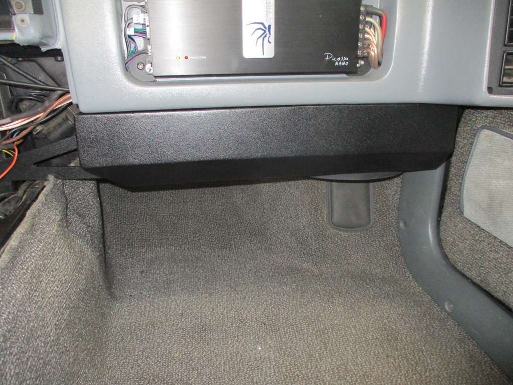
Played some AC/DC - Thunderstruck and Back N Black and turned it up. Sub works very well w/o and ringing or resonance. The base hits hard enough to shake the rear view mirror and carries into the house enough to annoy the cats. Overall it is louder than I need it to be and probably has more bass than needed in a Fiero as well. Overall I am super happy with the sound... Now I just need to finish putting the rest of the interior back together.
While the front wheel was off I went down a rabbit hole...
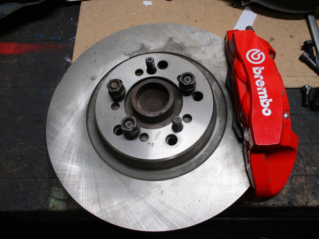
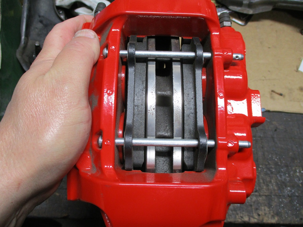
This is the Brembo 4 piston caliper that is a hydraulic match for the 88 Fiero calipers.
Hydraulic match means they can be swapped w/o changing clamp load or front/rear bias - which means they can be a front only upgrade while keeping the stock Fiero rear caliper with parking brake.
I am planning to use these calipers with my custom 88 front knuckles, but I am still a long ways away from installing those, so I decided to see if I could adapt these Brembo calipers to the stock 88 knuckle. So far so good... it appears the nose of the lower a-arm will clear the back side of the rotor. The caliper has to be rotated around the knuckle to allow for caliper bolt and caliper adapter bolts to coexist. This likely could cause some interference issues with the upper a-arm. If it does, I might try rotating it down vs. up. The rotor is 13" and 1.1" wide with some aggressive vanes for air movement. If everything clears, I will go ahead an install these (once they are painted blue!) in the front on my car. Like I said, they are a hydraulic match, so I can swap these calipers with the 88 front calipers w/o changing brake bias or brake feel.

Once the power cable was ran, then it was time to finish installing the dash and sub, wire up the radio and perform the first in car test. I think the finished install looks very good. There is 10" from the carpet to the bottom of the sub box.
Played some AC/DC - Thunderstruck and Back N Black and turned it up. Sub works very well w/o and ringing or resonance. The base hits hard enough to shake the rear view mirror and carries into the house enough to annoy the cats. Overall it is louder than I need it to be and probably has more bass than needed in a Fiero as well. Overall I am super happy with the sound... Now I just need to finish putting the rest of the interior back together.
While the front wheel was off I went down a rabbit hole...
This is the Brembo 4 piston caliper that is a hydraulic match for the 88 Fiero calipers.
Hydraulic match means they can be swapped w/o changing clamp load or front/rear bias - which means they can be a front only upgrade while keeping the stock Fiero rear caliper with parking brake.
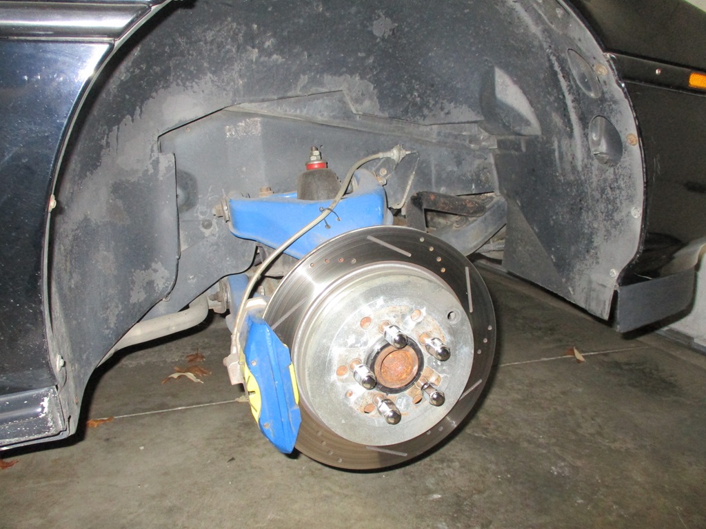
I am planning to use these calipers with my custom 88 front knuckles, but I am still a long ways away from installing those, so I decided to see if I could adapt these Brembo calipers to the stock 88 knuckle. So far so good... it appears the nose of the lower a-arm will clear the back side of the rotor. The caliper has to be rotated around the knuckle to allow for caliper bolt and caliper adapter bolts to coexist. This likely could cause some interference issues with the upper a-arm. If it does, I might try rotating it down vs. up. The rotor is 13" and 1.1" wide with some aggressive vanes for air movement. If everything clears, I will go ahead an install these (once they are painted blue!) in the front on my car. Like I said, they are a hydraulic match, so I can swap these calipers with the 88 front calipers w/o changing brake bias or brake feel.
The following 2 users liked this post by fieroguru:
Project GatTagO (03-17-2024), ryeguy2006a (03-19-2024)